1
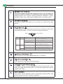
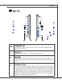
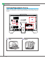
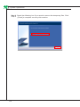
Wind Top AE2040 All-in-One (AIO) PC MS-AA16 (V1.X) System G52-AA161X7 ▍ Preface ▍ contents Copyright Notice������������������������������������������������������������������������������������ iii Trademarks������������������������������������������������������������������������������������������� iii Revision History������������������������������������������������������������������������������������ iii Upgrade and Warranty�������������������������������������������������������������������������� iv Acquisition of Replaceable Parts����������������������������������������������������������� iv Technical Support��������������������������������������������������������������������������������� iv Green Product Features�������������������������������������������������������������������������v Environmental Policy������������������������������������������������������������������������������v Safety Instructions��������������������������������������������������������������������������������� vi CE Conformity������������������������������������������������������������������������������������� viii FCC-B Radio Frequency Interference Statement������������������������������� viii WEEE Statement���������������������������������������������������������������������������������� ix 1. Overview���������������������������������������������������������������������������������������� 1-1 Packing Contents����������������������������������������������������������������������������������������1-2 System Overview����������������������������������������������������������������������������������������1-3 System Specifications���������������������������������������������������������������������������������1-9 Component Replacement & Upgrade�������������������������������������������������������1-10 2. Getting Started������������������������������������������������������������������������������� 2-1 Safety & Comfort Tips���������������������������������������������������������������������������������2-2 Having Good Working Habits����������������������������������������������������������������������2-3 Knowing the Keyboard (Optional)���������������������������������������������������������������2-4 Positioning your System������������������������������������������������������������������������������2-6 Connecting Peripheral Devices�������������������������������������������������������������������2-7 Connecting Power�������������������������������������������������������������������������������������2-13 3. System Operations������������������������������������������������������������������������� 3-1 System Booting Setup for the first time�������������������������������������������������������3-2 Creating System Recovery Disk�����������������������������������������������������������������3-3 Touch Panel Calibration (Only for single-touch model)������������������������������3-9 Network Connection under Windows��������������������������������������������������������3-11 RALINK Wireless LAN Connection (Optional)������������������������������������������3-16 SRS Premium Sound (Optional)���������������������������������������������������������������3-18 On-Screen Display (OSD)�������������������������������������������������������������������������3-20 Power Management����������������������������������������������������������������������������������3-23 System Recovery��������������������������������������������������������������������������������������3-25 ii MS-AA16 Copyright Notice The material in this document is the intellectual property of MICRO-STAR INTERNATIONAL. We take every care in the preparation of this document, but no guarantee is given as to the correctness of its contents. Our products are under continual improvement and we reserve the right to make changes without notice. Trademarks All trademarks are the properties of their respective owners. ■ MSI is a registered trademark of Micro-Star Int’l Co., Ltd. ■ Intel is a registered trademark of Intel Corporation. ■ AMD is a registered trademark of Advanced Micro Devices, Inc. ■ Realtek is a registered trademark of Realtek Semiconductor Corporation. ■ Windows is a registered trademark of Microsoft Corporation. ■ SRS Premium Sound, SRS and the symbol are trademarks of SRS Labs, Inc. Revision History Revision Revision History Date V1.1 First Release 2011/3 iii ▍ Preface Upgrade and Warranty Please note that certain components preinstalled in the product may be upgradable or replaceable by user’s request. To learn more about upgrade limitation, please refer to the specifications in the User’s Manual. For any further information about the product users purchased, please contact the local dealer. Do not attempt to upgrade or replace any component of the product if you are not an authorized dealer or service center, since it may cause the warranty void. It is strongly recommended that you contact the authorized dealer or service center for any upgrade or replace service. Acquisition of Replaceable Parts Please be noticed that the acquisition of replaceable parts (or compatible ones) of the product users purchased in certain countries or territories may be fulfilled by the manufacturer within 5 years at most since the product has been discontinued, depending on the official regulations declared at the time. ■ Please contact the manufacturer via http://www.msicomputer.com/msi_user/ msi_rma/ for the detailed information about the acquisition of spare parts. Technical Support If a problem arises with your system and no solution can be obtained from the user’s manual, please contact your place of purchase or local distributor. Alternatively, please try the following help resources for further guidance. ◙ ◙ Visit the MSI website for FAQ, technical guide, BIOS updates, driver updates and other information via http://www.msi.com/index.php?func=service Contact our technical staff via http://ocss.msi.com/ iv MS-AA16 Green Product Features ◙ ◙ ◙ ◙ ◙ ◙ Reduced energy consumption during use and stand-by Limited use of substances harmful to the environment and health Easily dismantled and recycled Reduced use of natural resources by encouraging recycling Extended product lifetime through easy upgrades Reduced solid waste production through take-back policy Environmental Policy ◙ ◙ ◙ ◙ The product has been designed to enable proper reuse of parts and recycling and should not be thrown away at its end of life. Users should contact the local authorized point of collection for recycling and disposing of their end-of-life products. Visit the MSI website and locate a nearby distributor for further recycling information: http://www.msi.com/index.php?func=html&name=service_ worldwide. Users may also reach us at [email protected] for information regarding proper Disposal, Take-back, Recycling, and Disassembly of MSI products. ▍ Preface Safety Instructions Read the safety instructions carefully and thoroughly. All cautions and warnings on the equipment or user’s manual should be noted. Keep the User’s Guide that comes with the package for future reference. Keep this equipment away from humidity and high temperature. Lay this equipment on a reliable flat surface before setting it up. ◙ Make sure that the power voltage is within its safety range and has been adjusted properly to the value of 100~240V before connecting the equipment to the power outlet. Do not disable the protective earth pin from the plug. The equipment must be connected to an earthed mains socket-outlet. ◙ Always unplug the AC power cord before installing any add-on card or module to the equipment. ◙ Always disconnect the AC power cord or switch the wall socket off if the equipment would be left unused for a certain time to achieve zero energy consumption. The ventilator on the enclosure is used for air convection and to prevent the equipment from overheating. Do not cover the ventilator. Do not leave the equipment in an unconditioned environment with a storage temperature above 60OC (140OF) or below 0OC (32OF), which may damage the equipment. NOTE: The maximum operating temperature is around 40OC. vi MS-AA16 Never pour any liquid into the opening that could damage or cause electrical shock. Place the power cord in a way that people are unlikely to step on it. Do not place anything on the power cord. When installing the coaxial cable to the TV Tuner, it is necessary to ensure that the metal shield is reliably connected to protective earthing system of the building. Cable distribution system should be grounded (earthed) in accordance with ANSI/NFPA 70, the National Electrical Code (NEC), in particular Section 820.93, Grounding of Outer Conductive Shield of a Coaxial Cable. Always keep the strong magnetic or electrical objects away from the equipment. If any of the following situations arises, get the equipment checked by service personnel: ◙ ◙ ◙ ◙ ◙ ◙ The power cord or plug is damaged. Liquid has penetrated into the equipment. The equipment has been exposed to moisture. The equipment does not work well or you can not get it work according to user’s manual. The equipment has dropped and damaged. The equipment has obvious sign of breakage. 1. The optical storage devices are classified as CLASS 1 LASER PRODUCT. Use of controls or adjustments or performance of procedures other than those specified is prohibited. 2. Do not touch the lens inside the drive. 廢電池請回收 For better environmental protection, waste batteries should be collected separately for recycling or special disposal. CAUTION: Danger of explosion if battery is incorrectly replaced. Replace only with the same or equivalent type recommended by the manufacturer. vii ▍ Preface CE Conformity Hereby, Micro Star International CO., LTD declares that this device is in compliance with the essential safety requirements and other relevant provisions set out in the European Directive. FCC-B Radio Frequency Interference Statement This equipment has been tested and found to comply with the limits for a Class B digital device, pursuant to Part 15 of the FCC Rules. These limits are designed to provide reasonable protection against harmful interference in a residential installation. This equipment generates, uses and can radiate radio frequency energy and, if not installed and used in accordance with the instruction manual, may cause harmful interference to radio communications. However, there is no guarantee that interference will not occur in a particular installation. If this equipment does cause harmful interference to radio or television reception, which can be determined by turning the equipment off and on, the user is encouraged to try to correct the interference by one or more of the measures listed below: ■ Reorient or relocate the receiving antenna. ■ Increase the separation between the equipment and receiver. ■ Connect the equipment into an outlet on a circuit different from that to which the receiver is connected. ■ Consult the dealer or an experienced radio/television technician for help. Notice 1 The changes or modifications not expressly approved by the party responsible for compliance could void the user’s authority to operate the equipment. Notice 2 Shielded interface cables and AC power cord, if any, must be used in order to comply with the emission limits. VOIR LA NOTICE D’INSTALLATION AVANT DE RACCORDER AU RESEAU. This device complies with Part 15 of the FCC Rules. Operation is subject to the following two conditions: 1. this device may not cause harmful interference, and 2. this device must accept any interference received, including interference that may cause undesired operation. viii MS-AA16 WEEE Statement (English) Under the European Union (“EU”) Directive on Waste Electrical and Electronic Equipment, Directive 2002/96/EC, which takes effect on August 13, 2005, products of “electrical and electronic equipment” cannot be discarded as municipal waste anymore and manufacturers of covered electronic equipment will be obligated to take back such products at the end of their useful life. (French) (Français) Au sujet de la directive européenne (EU) relative aux déchets des équipement électriques et électroniques, directive 2002/96/EC, prenant effet le 13 août 2005, que les produits électriques et électroniques ne peuvent être déposés dans les décharges ou tout simplement mis à la poubelle. Les fabricants de ces équipements seront obligés de récupérer certains produits en fin de vie. (German) (Deutsch) Gemäß der Richtlinie 2002/96/EG über Elektro- und Elektronik-Altgeräte dürfen Elektro- und Elektronik-Altgeräte nicht mehr als kommunale Abfälle entsorgt werden, die sich auf 13.August, 2005 wirken. Und der Hersteller von bedeckt Elektronik-Altgeräte gesetzlich zur gebrachten Produkte am Ende seines Baruchbarkeitsdauer zurückzunehmen. (Spanish) (Español) Bajo la directiva 2002/96/EC de la Unión Europea en materia de desechos y/o equipos electrónicos, con fecha de rigor desde el 13 de agosto de 2005, los productos clasificados como “eléctricos y equipos electrónicos” no pueden ser depositados en los contenedores habituales de su municipio, los fabricantes de equipos electrónicos, están obligados a hacerse cargo de dichos productos al termino de su período de vida. (Italian) (Italiano) In base alla Direttiva dell’Unione Europea (EU) sullo Smaltimento dei Materiali Elettrici ed Elettronici, Direttiva 2002/96/EC in vigore dal 13 Agosto 2005, prodotti appartenenti alla categoria dei Materiali Elettrici ed Elettronici non possono più essere eliminati come rifiuti municipali: i produttori di detti materiali saranno obbligati a ritirare ogni prodotto alla fine del suo ciclo di vita. (Russian) (Русский) В соответствии с директивой Европейского Союза (ЕС) по предотвращению загрязнения окружающей среды использованным электрическим и электронным оборудованием (директива WEEE 2002/96/EC), вступающей в силу 13 августа 2005 года, изделия, относящиеся к электрическому и электронному оборудованию, не могут рассматриваться как бытовой мусор, поэтому производители вышеперечисленного электронного оборудования обязаны принимать его для переработки по окончании срока службы. (Turkish) (Türkçe) Avrupa Birliği (AB) Kararnamesi Elektrik ve Elektronik Malzeme Atığı, 2002/96/ EC Kararnamesi altında 13 Ağustos 2005 tarihinden itibaren geçerli olmak üzere, elektrikli ve elektronik malzemeler diğer atıklar gibi çöpe atılamayacak ve bu elektonik cihazların üreticileri, cihazların kullanım süreleri bittikten sonra ürünleri geri toplamakla yükümlü olacaktır. ix ▍ Preface (Greek) (Ελληνικά) Σύμφωνα με την Οδηγία 2002/96/ΕΚ της Ευρωπαϊκής Ένωσης («ΕΕ») περί Απόρριψης Ηλεκτρικού και Ηλεκτρονικού Εξοπλισμού (WEEE), η οποία λαμβάνει ισχύ στις 13 Αυγούστου 2005, τα προϊόντα «ηλεκτρικού και ηλεκτρονικού εξοπλισμού» δεν είναι δυνατόν να απορριφθούν πλέον ως κοινά απορρίμματα και οι κατασκευαστές κεκαλυμμένου ηλεκτρονικού εξοπλισμού είναι υποχρεωμένοι να πάρουν πίσω αυτά τα προϊόντα στο τέλος της ωφέλιμης ζωής τους. (Polish) (Polski) Zgodnie z Dyrektywą Unii Europejskiej (“UE”) dotyczącą odpadów produktów elektrycznych i elektronicznych (Dyrektywa 2002/96/EC), która wchodzi w życie 13 sierpnia 2005, tzw. “produkty oraz wyposażenie elektryczne i elektroniczne “ nie mogą być traktowane jako śmieci komunalne, tak więc producenci tych produktów będą zobowiązani do odbierania ich w momencie gdy produkt jest wycofywany z użycia. (Hungarian) (Magyar) Az Európai Unió („EU”) 2005. augusztus 13-án hatályba lépő, az elektromos és elektronikus berendezések hulladékairól szóló 2002/96/EK irányelve szerint az elektromos és elektronikus berendezések többé nem kezelhetőek lakossági hulladékként, és az ilyen elektronikus berendezések gyártói kötelessé válnak az ilyen termékek visszavételére azok hasznos élettartama végén. (Czech) (Čeština) Podle směrnice Evropské unie (“EU”) o likvidaci elektrických a elektronických výrobků 2002/96/EC platné od 13. srpna 2005 je zakázáno likvidovat “elektrické a elektronické výrobky” v běžném komunálním odpadu a výrobci elektronických výrobků, na které se tato směrnice vztahuje, budou povinni odebírat takové výrobky zpět po skončení jejich životnosti. (Traditional Chinese ) (繁體中文) 歐盟已制訂有關廢電機電子設備法令,亦即自2005年8月13日 生效的2002/96/EC,明文規定「電機電子設備產品」不可再以都市廢棄物處理,且所有相關電 子設備製造商,均須在產品使用壽命結束後進行回收。 (Simplified Chinese ) (简体中文) 欧盟已制订有关废电机电子设备法令,亦即自2005年8月13日生 效的2002/96/EC,明文规定「电机电子设备产品」不可再以都市废弃物处理,且所有相关电子 设备制造商,均须在产品使用寿命结束后进行回收。 (Japanese) (日本語) 2005年8月13日以降にEU加盟国を流通する電気・電子製品にはWEEE指 令によりゴミ箱に×印のリサイクルマークの表示が義務づけられており、廃棄物として捨てる ことの禁止とリサイクルが義務づけられています。 (Korean) (한국어) 2005년 8월 13일자로 시행된 폐전기전자제품에 대한 유럽연합(“EU”) 지침, 지 침 2002/96/EC에 의거하여, “전기전자제품”은 일반 쓰레기로 폐기할 수 없으며 제품의 수명이 다 하면 해당 전자제품의 제조업체가 이러한 제품을 회수할 책임이 있습니다. (Vietnam) (Tieng Viet) Theo Hướng dẫn của Liên minh Châu Âu (“EU”) về Thiết bị điện & điện tử đã qua sử dụng, Hướng dẫn 2002/96/EC, vốn đã có hiệu lực vào ngày 13/8/2005, các sản phẩm thuộc “thiết bị điện và điện tử” sẽ không còn được vứt bỏ như là rác thải đô thị nữa và các nhà sản xuất thiết bị điện tử tuân thủ hướng dẫn sẽ phải thu hồi các sản phẩm này vào cuối vòng đời. ภายใต้ข้อกำหนดของสหภาพยุโรป (“EU”) เกี่ยวกับของเสียจากอุปกรณ์ไฟฟ้า (Thai) (ไทย) และอิเล็กทรอนิกส์ เลขที่ 2002/96/EC ซึ่งมีผลบังคับใช้ตั้งแต่วันที่ 13 สิงหาคม 2005 ผู้ใช้ไม่สามารถทิ้งผลิ ตภัณฑ์ที่เป็น “อุปกรณ์ไฟฟ้าและอิเล็กทรอนิกส์” ปะปนกับของเสียทั่วไปของชุมชนได้อีกต่อไป และผู้ผลิตอุป กรณ์อิเล็กทรอนิกส์ดังกล่าวจะถูกบังคับให้นำผลิตภัณฑ์ดังกล่าวกลับคืนเมื่อ สิ้นสุดอายุการใช้งานของผลิตภัณฑ์ MS-AA16 (Indonesia) (Bahasa Indonesia) Sesuai dengan Regulasi Uni Eropa (“UE”) perihal WEEE (Limbah Peralatan Listrik dan Elektronik), Directive 2002/96/EC, yang berlaku sejak 13, 2005, produk “peralatan listrik dan elektronik” tidak lagi dapat dibuang sebagai sampah umum dan pabrik peralatan elektronik diwajibkan untuk mengambil kembali produk tersebut pada saat masa pakainya habis. (Serbian) (Srpski) Po Direktivi Evropske unije (“EU”) o odbačenoj ekektronskoj i električnoj opremi, Direktiva 2002/96/EC, koja stupa na snagu od 13. Avgusta 2005, proizvodi koji spadaju pod “elektronsku i električnu opremu” ne mogu više biti odbačeni kao običan otpad i proizvođači ove opreme biće prinuđeni da uzmu natrag ove proizvode na kraju njihovog uobičajenog veka trajanja. (Netherlands) (Nederlands) De richtlijn van de Europese Unie (EU) met betrekking tot Vervuiling van Electrische en Electronische producten (2002/96/EC), die op 13 Augustus 2005 in zal gaan kunnen niet meer beschouwd worden als vervuiling. Fabrikanten van dit soort producten worden verplicht om producten retour te nemen aan het eind van hun levenscyclus. (Romanian) (Română) În baza Directivei Uniunii Europene (“UE”) privind Evacuarea Echipamentului Electric şi Electronic, Directiva 2002/96/EC, care intră în vigoare pe 13 august, 2005, produsele din categoria “echipament electric şi electronic” nu mai pot fi evacuate ca deşeuri municipale, iar fabricanţii echipamentului electronic vizat vor fi obligaţi să primească înapoi produsele respective la sfârşitul duratei lor de utilizare. (Portuguese) (Português) De acordo com a Directiva 2002/96/EC de Resíduos de Equipamentos Eléctricos e Electrónicos da União Europeia (UE), efectiva desde o 13 de Agosto do ano 2005, os produtos de “equipamento eléctrico e electrónico” não podem ser descartados como resíduo municipal e os fabricantes do equipamento electrónico sujeitos a esta legislação estarão obligados a recolhar estes produtos ao finalizar sua vida útil. (Swedish) (Svenska) Under Europeiska unionens (“EU”) Weee-direktiv (Waste Electrical and Electronic Equipment), Direktiv 2002/96/EC, vilket trädde i kraft 13 augusti, 2005, kan inte produkter från “elektriska och elektroniska utrustningar” kastas i den vanliga hushållssoporna längre och tillverkare av inbyggd elektronisk utrustning kommer att tvingas att ta tillbaka sådan produkter när de är förbrukade. (Finnish) (Suomi) Euroopan unionin (EU) 13.8.2005 voimaan tulleen sähkö- ja elektroniikkalaiteromua koskevan direktiivin 2002/96/EY mukaisesti ”sähkö- ja elektroniikkalaitteita” ei saa enää hävittää talousjätteiden mukana. Direktiivin alaisen sähkö- tai elektroniikkalaitteen valmistajan on otettava laitteet takaisin niiden käyttöiän päättyessä. (Slovak) (Slovenčina) Na základe smernice Európskej únie („EU“) o elektrických a elektronických zariadeniach číslo 2002/96/ES, ktorá vstúpila do platnosti 13. augusta 2005, výrobky, ktorými sú „elektrické a elektronické zariadenia” nesmú byť zneškodňované spolu s komunálnym odpadom a výrobcovia patričných elektronických zariadení sú povinní takéto výrobky na konci životnosti prevziať naspäť. (Slovenian) (Slovenščina) Skladno z določili direktive Evropske unije (“EU”) o odpadni električni in elektronski opremi, Direktiva 2002/96/ES, ki je veljavna od 13. avgusta, izdelkov “električne in elektronske opreme” ni dovoljeno odstranjevati kot običajne komunalne odpadke, proizvajalci zadevne elektronske opreme pa so zavezani, da tovrstne izdelke na koncu njihove življenjske dobe sprejmejo nazaj. xi ▍ Preface (Danish) (Dansk) I henhold til direktiv fra den europæiske union (EU) vedrørende elektrisk og elektronisk affald , Direktiv 2002/96/EC, som træder i kraft den 13. august 2005, må produkter som “elektrisk og elektronisk udstyr” ikke mere bortskaffes som kommunalt affald. Producenter af det pågældende, elektroniske udstyr vil være forpligtet til at tage disse produkter tilbage ved afslutningen på produkternes levetid. (Norwegian) (Norsk) Under den europeiske unionens (“EU”) direktiv om deponering av elektronisk og elektrisk utstyr, direktiv 2002/96/EC, som trer i effekt 13. august 2005, kan ikke produkter av “elektronisk og elektrisk ustyr” lenger deponeres som husholdningsavfall og fabrikantene av disse produktene er forpliktet å ta tilbake slike produkter ved slutten av produktets levetid. (Bulgarian) (български) Според директивата на Европейския съюз относно отпадъците от електрическо и електронно оборудване, директива 2002/96/EC, важаща от 13 август, 2005 г., електрическо и електронно оборудване не може да се изхвърля заедно с битовите отпадъци и производителите на такова оборудване са задължени да приемат обратно съответните продукти в края на експлоатационния им период. (Croatian) (Hrvatski) U okviru Direktive Europske Unije (“EU”) o Otpadnim električnim i elektroničkim uređajima, Direktiva 2002/96/EC, koja je na snazi od 13. kolovoza 2005., “električni i elektronički uređaji” se ne smiju više bacati zajedno s kućnim otpadom i proizvođači su obvezni zbrinuti takve proizvode na kraju njihovog životnog vijeka. (Estonia) (Eesti) Vastavalt Euroopa Liidu (“EL”) direktiivile 2002/96/EÜ (elektri- ja elektroonikaseadmete jäätmete kohta), mis jõustus 13. augustil 2005, on keelatud kodumajapidamiste “elektri- ja elektroonikaseadmete” jäätmete hävitamine koos majapidamisjäätmetega, ja elektrija elektroonikaseadmete tootjad on kohustatud sellised tooted pärast nende kasutuselt kõrvaldamist tagasi võtma. xii Chapter 1 Overview Wind Top AE2040 is integrated in design, selecting a stylish appearance with a glassy frame, which displays the simplicity of modern individualism and the comfort of home. Furthermore, it is accompanied with the best computer features, such as instant message, low acoustics, energy saving, and 802.11 b/g/n wireless internet capability so you may roam freely in the realm of cyberspace. ▍ Overview Packing Contents Wind Top Series AC/DC Adapter AC Power Cord LCD Display Wiper Driver/Utility Disk User Manual & Quick Guide Keyboard (Optional) Mouse (Optional) Stylus (Optional) * Please contact us immediately if any of the items is damaged or missing. * The picture is for your reference only and your packing contents may slightly vary depending on the model you purchased. 1-2 MS-AA16 System Overview Front View 2 3 1 4 1 Microphone 2 Webcam 3 IR Receiver (Optional) 4 LCD Display The built-in microphone can be used for video chatting online. The built-in webcam with the microphone can be used for picture taking, video recoding, online conferencing and any other interactive applications. This infrared receiver is provided for remote control. The 20-inch TFT LCD display is with an optimal resolution of 1600 X 900 and standard proportion of 16:9 widescreen. 1-3 ▍ Overview Rear View 1 2 1 4 3 5 1 15 8 12 14 13 6 7 8 9 10 11 Important We suggest that you connect the AC/DC adapter to your AIO PC first and then connect the AC power cord to the socket-outlet for safety concerns. 1-4 MS-AA16 1 Ventilator 2 Optical Disk Drive 3 Card Reader Drive 4 Stand 5 Cable Routing Hole 6 Power Jack 7 VGA-In Port (Optional) 8 USB Port The ventilator on the enclosure is used for air convection and to prevent the equipment from overheating. Do not cover the ventilator. A DVD Super-Multi drive is integrated for your home entertainment. (Blu-ray is optional.) The built-in card reader may support various types of memory card, such as XD (eXtreme Digital), SD (Secure Digital), SDHC (SD High Capacity), MS (Memory Stick), MS Pro (Memory Stick Pro) or MMC (Multi-Media Card) cards that usually used in devices like digital cameras, MP3 players, mobile phones and PDAs. Contact the local dealer for further information and please be noted that the supported memory cards may vary without notice. Use this stand to position your system on a flat and stable surface. Route the cables through the cable routing hole to avoid cable spaghetti when connecting devices. The AC/DC adapter converts AC power to DC power for this jack. Power supplied through this jack supplies power to the PC. To prevent damage to the PC, always use the supplied power adapter. The DB15-pin female connector is provided for VGA-interface device. The USB (Universal Serial Bus) port is provided for attaching USB devices such as mouse, keyboard, printer, scanner, camera, PDA or other USB-compatible devices. 1-5 ▍ Overview 9 10 11 HDMI-Out Port (Optional) The High-Definition Multimedia Interface (HDMI) is an all-digital audio/video interface capable of transmitting uncompressed streams. HDMI supports all TV format, including standard, enhanced, or highdefinition video, plus multi-channel digital audio on a single cable. eSATA Port (Optional) The eSATA (External-SATA) port is provided for eSATA hard disk drives. RJ-45 LAN Jack The standard RJ-45 LAN jack is provided for connection to the Local Area Network (LAN). You can connect a network cable to it. Yellow LED Color LED State Condition Left Yellow Off LAN link is not established. On (steady state) LAN link is established. On (brighter & pulsing) The computer is communicating with another computer on the LAN. Off 10 Mbit/sec data rate is selected. On 100 Mbit/sec data rate is selected. On 1000 Mbit/sec data rate is selected. Right Green Orange 12 Headphone Jack (Green) 13 Microphone Jack (Pink) 14 Optical S/PDIF-Out Jack (Optional) 15 1-6 Green/ Orange This connector is provided for headphones or speakers. This connector is provided for microphones. This S/PDIF (Sony & Philips Digital Interconnect Format) jack is provided for digital audio transmission to external speakers through an optical fiber cable. Stereo Speakers The built-in stereo speakers deliver high quality sound blaster with stereo system and Hi-Fi function supported. MS-AA16 Side View 1 6 2 3 7 4 9 5 11 8 10 12 1 Optical Disk Drive 2 Eject Button 3 Eject Hole 4 Card Reader Drive A DVD Super-Multi drive is integrated for your home entertainment. (Blu-ray is optional.) Press the eject button to open the optical disk drive. Insert a thin, straight object (such as a paper clip) into the eject hole to open the optical disk drive manually if the eject button does not work. The built-in card reader may support various types of memory card, such as XD (eXtreme Digital), SD (Secure Digital), SDHC (SD High Capacity), MS (Memory Stick), MS Pro (Memory Stick Pro) or MMC (Multi-Media Card) cards that usually used in devices like digital cameras, MP3 players, mobile phones and PDAs. Contact the local dealer for further information and please be noted that the supported memory cards may vary without notice. 1-7 ▍ Overview 5 USB Ports 6 Ventilator 7 System Power Button/LED The USB (Universal Serial Bus) port is provided for attaching USB devices such as mouse, keyboard, printer, scanner, camera, PDA or other USB-compatible devices. The ventilator on the enclosure is used for air convection and to prevent the equipment from overheating. Do not cover the ventilator. Press the system power button to turn the system on or off. The power LED glows when the system is turned on and goes off when the system is shut down. In terms of power saving, the LED blinks in S3 (Suspend to RAM) mode and goes off in S4 (Suspend to Disk) mode. Pressing the system power button will wake the system up from power saving mode. 8 MENU Button 9 Right Button Press this button to view the OSD menu or enter into the submenu. This button indicates the cursor movement or OSD manual selection in incremental values. 10 Left Button 11 AUTO Button 12 LCD Power Button This button indicates the cursor movement or OSD manual selection in decremental values. Press this button to view the video mode menu or exit the submenu. Press this button to power ON/OFF the monitor. 1-8 MS-AA16 System Specifications Processor ■ Intel® Core™ i series processor Chipset ■ Intel® HM55 chipset Memory ■ 2 DDR3 SO-DIMM slots ■ Supports the maximum of 4GB LAN ■ Wired LAN: supported by Realtek® RTL8111DL Gigabit Ethernet controller ■ Wireless LAN: optionally supported through Mini PCI-E WLAN module Audio ■ HDA Codec by Realtek® ALCxxx series ■ Compliant with Azalia 1.0 specs Display ■ 20-inch TFT LCD display with an optimal resolution of 1600 X 900 and standard proportion of 16:9 widescreen Rear Panel I/O ■ 1 DC power jack ■ 1 VGA-In port (optional) ■ 4 USB ports ■ 1 HDMI-Out port (optional) ■ 1 eSATA port (optional) ■ 1 RJ-45 LAN jack ■ 1 microphone jack ■ 1 headphone/speaker jack ■ 1 optical S/PDIF-Out jack (optional) Storage ■ Hard Disk Drive: 3.5”, SATAII ■ Optical Disk Drive: Slim DVD Super Multi (Blu-ray is optional) ■ Card Reader: 4 in 1 (XD, SD, MMC, MS) Stereo Speaker ■ 2 Hi-Fi stereo speakers with SRS Premium Sound (3W) WebCam ■ 1.3M WebCam with microphone Power Supply ■ 90~120 watt AC/ DC adapter with active PFC ■ Input: 100-240V~, 50-60Hz, 1.5A ■ Output: 19V 4.74A 1-9 ▍ Overview Component Replacement & Upgrade Please note that certain components preinstalled in the product may be upgradable or replaceable by user’s request depending on the models users purchased. 5 2 1 4 1 CPU 1-10 3 2 Memory MS-AA16 3 Hard Disk Drive 4 Wireless LAN Card 5 Optical Disk Drive If the specified component has been determined by the MSI engineer or store as problematic or defective and may incur the need for replacement, you may bring the product for repair along with the warranty card, purchase invoice or receipt to the MSI-authorized service center closest to your location for assistance. To learn more about upgrade limitation, please refer to the specifications in the User’s Manual. For any further information on the product users purchased, please contact the local dealer. Do not attempt to upgrade or replace any component of the product if you are not an authorized dealer or service center, since it may cause the warranty void. It is strongly recommended that you contact the authorized dealer or service center for any upgrade or replace service. 1-11 Chapter 2 Getting Started This chapter provides you with the information on hardware setup procedures. While connecting peripheral devices, be careful in holding the devices and use a grounded wrist strap to avoid static electricity. ▍ Getting Started Safety & Comfort Tips The AIO PC is a portable platform that allows you to work anywhere. However, choosing a good workspace is important if you have to work with your PC for a long period of time. ■ ■ ■ ■ ■ ■ ■ ■ Your work area should have enough illumination. Choose the proper desk and chair and adjust their height to fit your posture when operating. When sitting on the chair, adjust the chair’s back (if available) to support your back comfortably. Place you feet flat and naturally on the floor, so that your knees and elbows have the proper position (about 90-degree) when operating. Put your hands on the desk naturally to support your wrists. Adjust the angle/position of the AIO PC to have an optimal view. Avoid using your PC in a place where discomfort may occur (such as on the bed). The AIO PC is an electrical device. Please treat it with great care to avoid personal injury. 1. Keep your hands and feet with optimal comfort. 2. Adjust the angle and position of the monitor. 3. Adjust the desk’s height. 4. Sit straight and keep a good posture. 5. Adjust the chair’s height. 2-2 MS-AA16 Having Good Working Habits Having good working habits is important if you have to work with your AIO PC for long periods of time; otherwise, it may cause discomfort or injury to you. Please keep the following tips in mind when operating. ■ ■ ■ Change your posture frequently. Stretch and exercise your body regularly. Remember to take a break after working for a period of time. 2-3 ▍ Getting Started Knowing the Keyboard (Optional) ▶ Specifications ■ Compatible with EU/UK/US/JP/KR language layout ■ Isolated keycap for easy typing ■ Low profile with silk printing technology ■ USB interface for all Windows® OS ■ Keystroke life: 12 million ■ Dimensions: 376.4 (L) X 155.09 (W) X 21.91 (H) mm ■ Cable Length: 150cm ■ Weight: 440g ▶ Features ■ Multimedia function keys with AIO PC ■ New isolated keycap for easy typing ■ Soft-touch and tactile feedback for comfortable typing ■ New concept elegant and slim keyboard in streamline shape ■ Compact size for space saving ■ Especially fit for MSI LCD display ■ Compatible with Windows® 2000/ ME/ XP/ Vista/ 7 ■ Built-in function hot keys ■ Access favorite websites and applications with one touch hot keys * The illustration of keyboard is for reference only. Actual product specifications may vary with territories. 2-4 MS-AA16 ▶ ▶ Multimedia Keys Fn + F7 Backward to previous track Fn + F8 Play and pause Fn + F9 Forward to next track Fn + F10 Mute function Fn + F11 Volume down Fn + F12 Volume up Hot Keys Fn + F1 Launch the default E-Mail applications Fn + F2 Lanuch the default internet browser and go to the default home page Fn + F3 Back to the previous web page Fn + F4 Forward to the next web page Fn + C Calculator Fn + Z Sleep mode (energy saving) Fn + W Wireless LAN Fn + K Camera 2-5 ▍ Getting Started Positioning your System Positioning Your AIO PC Step 1. Place your AIO PC on a flat and steady surface such as a table or desk. Step 2. Pull the stand open and tilt the LCD display to an angle of between 10 and 20 degrees to suit your preference. This helps to reduce your eye strain and muscle fatigue. 0 2-6 o 10 o 0 o 20 o MS-AA16 Connecting Peripheral Devices The I/O (input/output) ports on the rear panel allow you to connect peripheral devices. All devices listed here are for reference only. Connecting the USB Devices This AIO PC provides USB ports for connecting various USB devices, such as mouse, keyboard, digital camera, webcam, printer, external optical storage device,.. and etc. To connect these devices, install the drivers for each device first if necessary, and then connect the device to the AIO PC. This AIO PC is capable of auto detecting the USB devices installed, and if there is no detection of the devices, please manually enable the USB devices by going to Start Menu / Control Panel / Add Hardware to add the new device. 2-7 ▍ Getting Started Connecting VGA-In & HDMI-Out Devices (Optional) This AIO PC provides a VGA port and an HDMI port for connection to external monitors, projectors, set-top boxes, DVD players, digital video cameras, mini notebooks, digital cameras, etc. VGA (Video Graphics Array) is a graphics display system for PCs. VGA connectors and their associated cabling are always used solely to carry analog video signals along with digital clock and data. HDMI (High Definition Multimedia Interface) is a new interface standard for PCs, displays and consumer electronics devices that supports standard, enhanced and high-definition video, plus multi-channel digital audio on a single cable. 2-8 MS-AA16 To connect the VGA/HDMI device, first make sure the AIO PC and the targeted device are both powered off, and then connect the cable of the device to the VGA/HDMI port of your AIO PC. 2-9 ▍ Getting Started Connecting the External SATA Hard Disk Drive (Optional) The eSATA Connector allows you to connect an external Serial ATA hard disk device. The eSATA standard interface supports “plug-and-play” technology, so that you can connect and remove the eSATA devices without turning off the AIO PC. To connect the eSATA hard disk device, simply connect the cable of the device to the eSATA Connector of your AIO PC. 2-10 MS-AA16 Connecting the Communication Device Wired LAN The RJ-45 connector of the AIO PC allows you to connect the LAN (local area network) devices, such as a hub, switch and gateway, to build a network connection. For more instructions or detailed steps on connecting to the LAN, please ask your MIS staff or network manager for help. 2-11 ▍ Getting Started Wireless LAN (Optional) This AIO PC is equipped with wireless LAN module which allows users to perform fast data transmission with standard IEEE 802.11 technology for wireless LAN. This gives users the mobility to move around within a broad coverage area and still be connected to the network. By using the 64-bit/128-bit Wired Equivalent Privacy (WEP) encryption technology and Wi-Fi Protected Access feature, the optional built-in wirelesses LAN is capable to achieve a more efficient and a more secure solution to the wireless communication. For more instructions or detailed steps on connecting to the Wireless LAN, please ask your MIS staff or network manager for help. 2-12 MS-AA16 Connecting Power Connecting the AC Power Step 1. Unpack the package to find the AC/DC adapter and AC power cord. Step 2. Assemble the AC/DC adapter and the AC power cord. Step 3. Plug the DC end of the adapter to the AIO PC, and the male end of the AC power cord to the electrical outlet. Important We suggest that you connect the AC/DC adapter to your AIO PC first and then connect the AC power cord to the socket-outlet for safety concerns. Disconnecting the AC Power Step 4. Unplug the AC power cord from the electrical outlet first. Step 5. Unplug the connector from the AIO PC. Step 6. Disassemble the AC power cord and the AC/DC adapter. Important When unplugging the AC power cord, always hold the connector part of the cord. Never pull the cord directly! 5 4 1 2 3 6 2-13 Chapter 3 System Operations This chapter provides you with essential information on system operations, such as system boot setup, recovery disk creation, network connection, SRS Premium Sound, and so on. Important • It is highly recommended that you create a system recovery disk as the backup solution in the event of a catastrophic disk failure or other accidents. • All information is subject to change without prior notice. ▍ System Operations System Booting Setup for the first time For the first-time use, you will need to go over the following steps to start using your Wind Top Series AIO PC. The entire booting setup will take you around 30 minutes. Step 1. Windows setup starts running. Please wait until Windows setup finishes the progress loading. Step 2. Select the language of the operating system and click [Next] to continue. Step 3. Choose the “Country or region”, “Time and currency”, and “Keyboard layout” you need. Click [Next] to continue. Step 4. Choose a user name for your account and name your computer to distinguish it on the network. Click [Next] to continue. Step 5. Set a password for your account to protect your user account from unwanted users. (Leave this field blank if no need for password.) Click [Next] to continue. Step 6. Please read the license terms. Check the “I accept the license terms” box and click [Next] to continue. Step 7. Select [Use recommended settings] for “Help protect your computer and improve Windows automatically.” Step 8. Review your time and date settings. Click [Next] to continue. Step 9. Please choose a wireless network you intend to join from the provided WLAN list. Click [Next] to continue. You may also click [Skip] to skip this step and set up the WLAN later. Step 10. Followingly comes the anti-virus software screen. Click [Agree] to accept the license agreement terms and activate the anti-virus software. Alternatively, choose [No, I do not want to protect my PC.] to proceed without activating the anti-virus software. Step 11. The “Software Installation Menu” pops up. Click [Install] to continue. Step 12. The software is being installed. Please do not turn off the computer when software installation is running. When the progress bar completes loading, click [Finish] to continue. Step 13. The system enters the Windows 7 OS to start its personalized settings. Get ready to explore your AIO PC after the personalized settings are done. Have fun with it! 3-2 MS-AA16 Creating System Recovery Disk For the first-time use, it is highly recommended that you create a system recovery disk as the backup solution in the event of a catastrophic disk failure or other accidents. Before moving forward, please make sure your system booting setup is complete and go over the following procedures to get it done. Step 1. Double-click the “BurnRecovery” icon on the desktop to launch the Recovery Disc Creation Tool. Please note that it may take a while for the operating system to prepare recovery files. Step 2. Click [Next] to start the image creation of the recovery disk. 3-3 ▍ System Operations Step 3. Select [Create and burn a recovery disk] and click [Next] to continue. Alternatively, choose [Advanced] to bring forth advanced options. Choose between the provided options and click [Next] to continue. 3-4 MS-AA16 Step 4. The progress bar starts running to create the image of recovery disk. It takes some time to finish the processing. Step 5. Follow the on-screen instructions to prepare enough number of blank DVD disks. Insert the blank DVD disk into the optical disk drive and click [Next] to continue. 3-5 ▍ System Operations Step 6. The Windows Disc Image Burner pops up. Click [Burn] to start the burning progress. It takes a while to finish the processing. 3-6 MS-AA16 Step 7. On completion of the disk creation, click [Close] to exit and take out the disk. Follow the on-screen instructions to create all recovery disks. Step 8. All recovery disks have been successfully created. Please store the disks carefully and click [Next] to continue. 3-7 ▍ System Operations Step 9. Check the following box if you want to remove the temporary files. Click [Finish] to complete recovery disk creation. 3-8 MS-AA16 Touch Panel Calibration (Only for single-touch model) Wind Top Series AIO PC has touch panel function. If the mouse cursor can not match the move, users could use the IdeaCom TSC tool installed in system to adjust the accuracy of the touch panel. Please go over the following steps to get it done. Step 1. Locate the IdeaCom TSC tool at [Start] > [All Programs] > [IdeaCom TSC]. Step 2. Click [Calibration] to bring forth the default 9-point calibration. Follow the on-screen instructions to calibrate the touch panel. 3-9 ▍ System Operations Step 3. For advanced settings, click [IdeaCom TSC] to launch the setup utility. Three calibration modes are provided: 4 points, 9 points, and 25 points. We suggest that users choose 9 points to adjust the touch panel. If users desire the best precision, then choose 25 points instead. Click [Calibration] to proceed and follow the on-screen instructions to calibrate the touch panel. Important • Do not touch the screen directly with any sharp-pointed object. • Actual product specifications may vary with territories. 3-10 MS-AA16 Network Connection under Windows Wired LAN Step 1. Go to [Start] > [Control Panel]. Step 2. Select [Connect to the Internet] under [Network and Internet]. 3-11 ▍ System Operations Step 3. Select [Broadband (PPPoE)] to connect using DSL or cable that requires a user name and password. Step 4. Type the information from your Internet Service Provider (ISP) and click [Connect] to establish your LAN connection. 3-12 MS-AA16 Wireless LAN Step 1. Go to [Start] > [Control Panel]. Step 2. Select [Connect to the Internet] under [Network and Internet]. 3-13 ▍ System Operations Step 3. Select [Wireless] to connect using a wireless router or a wireless network. Step 4. A list of available WLAN connections pops up. Choose a connection from the list or click [Open Network and Sharing Center] to establish a new connection. Step 5. To establish a new WLAN connection, select [Set up a new connection or network] in [Network and Sharing Center]. 3-14 MS-AA16 Step 6. Followingly, choose [Manually connect to a wireless network] and click [Next] to continue. Step 7. Enter information for the wireless network you intend to add and click [Next] to proceed. Step 8. A new WLAN connection has been made. Click [Close] to exit or select [Change connection settings] to modify the WLAN settings. 3-15 ▍ System Operations RALINK Wireless LAN Connection (Optional) Step 1. Right-click the Ralink Wireless LAN Card status icon in the lower right corner, and then click Launch Config Utility. Step 2. The window displays some available wireless networks. Choose a network, and then click Connect. 3-16 MS-AA16 Step 3. There may prompt you to enter a key. Type the network key and then click OK. Step 4. Now, you’re ready to browse the Web wirelessly. 3-17 ▍ System Operations SRS Premium Sound (Optional) SRS Premium Sound is a comprehensive suite of state-of-the-art audio technologies that deliver a superior entertainment experience for playback of music, video and game content on the PC. With SRS Premium Sound your audio entertainment experience will sound better - more natural and immersive, with deeper bass, clearer dialog and outstanding surround sound. Features: ■ ■ ■ ■ ■ Premium audio experience for music, video and games on the PC Immersive surround sound experience from internal or external speakers and even headphones Greater volume without degrading audio quality Crystal clear dialog Deep, rich bass Using the SRS Premium Sound Step 1. Double-click the Realtek HD Audio tray icon at the lower right corner of the screen to launch the SRS Premium Sound. Step 2. The Realtek HD Audio Manager pops up. Click the SRS tab and check the “Enable SRS® Technology” box. 3-18 MS-AA16 Step 3. Choose the audio content you are listening to. The SRS Premium Sound will automatically process the specified audio signals to deliver enhanced audio performance. Step 4. The following settings allow for specific control of SRS tuning parameters and are provided for External Speakers and Headphones. ■ ■ ■ ■ ■ ■ SRS Center: adjusts the center-channel sound SRS Space: adjusts the amount and width of the sound stage TruBass Level: adjusts the bass or low frequencies TruBass Speaker Size: should be used to select the size of the speakers Focus Level: adjusts the frequencies that include vocals/voice SRS Definition: adjusts the high frequencies CAUTION: These settings are very sensitive and should be used by advanced users. 3-19 ▍ System Operations On-Screen Display (OSD) The on-screen display (OSD) allows you to tune the viewing options of the monitor, such as brightness, contrast, positioning, and language. It can be activated by buttons at the right side of the monitor. Step 1. Press the MENU button to bring up the OSD main menu. Use the Right and Left arrow buttons to select the desired function menu and press the MENU button to enter. Use the Right and Left arrow buttons to select or tune the values to suit your personal preferences. After the settings are done, press the AUTO button to exit. Adjusting contrast and brightness 3-20 Adjusting color MS-AA16 Adjusting signal source Adjusting positioning & timeout Specifying language Resetting system Reading system information Adjusting wide screen mode 3-21 ▍ System Operations Step 2. Press the Right & Left arrow buttons to adjust the system volume. Step 3. Press the AUTO button to view the video mode menu. Use the Right & Left arrow buttons to select a desired mode and press the AUTO button to exit after the selection is made. Important Whenever any error takes place and incurs abnormal display or volume malfunction, enter the OSD menu and reset your monitor to restore all settings to manufacturer default for optimal performance. 3-22 MS-AA16 Power Management Power management of personal computers (PCs) and monitors has the potential to save significant amounts of electricity as well as deliver environmental benefits. To be energy efficient, turn off your display or set your PC to sleep mode after a period of user inactivity. Power Management in Windows OS ■ [Power Options] in Windows OS allow you to control the power management features of your display, hard drive, and battery. Go to [Start] > [Control Panel] > [System and Security]. Then click on the [Power Options] link. Select a power plan that suits your personal needs. You may also finetune the settings by clicking [Change plan settings]. 3-23 ▍ System Operations ■ The Shut Down Computer menu presents the options of Sleep (S3/S4) & Shut Down (S5) for rapid and easy management of your system power. Waking the System Up The computer shall be able to wake up from power saving mode in response to a command from any of the following: ■ the power button, ■ the mouse, ■ the keyboard. Energy Saving Tips: ■ Turn off the monitor by pressing the LCD power button of user inactivity. ■ Utilize the (Fn + Z) sleep mode keys to turn into power saving mode. Tune the settings in Power Options under Windows OS to optimize your PC’s power management. Install power saving software to manage your PC’s energy consumption. Always disconnect the AC power cord or switch the wall socket off if your PC would be left unused for a certain time to achieve zero energy consumption. ■ ■ ■ 3-24 after a period MS-AA16 System Recovery Important The System Recovery Function is only available on systems bundled with Windows OS and MSI utilities by default. The purposes for using the System Recovery Function may include: ■ Restore the system back to the initial status of original manufacturer’s default settings. ■ When some errors have occurred to the operating system in use. ■ When the operating system is affected by virus and is not able to work normally. Before using the System Recovery Function, please backup the important data saved on your system drive to other storage devices. If the following solution fails to recover your system, please contact the authorized local distributor or service center for further assistance. Recovering the System with the F3 Hotkey If the system encounters non-recoverable problems, it is always recommended that you try the F3 hotkey to recover your system with the recovery partition of the hard disk drive first. Follow the instructions below to continue: 1. Restart the system. 2. Press the F3 hotkey on the keyboard when the following image appears. 3-25 ▍ System Operations 3. Select [Windows Setup] from the Windows Boot Manager menu. 4. Select [MSI Recovery Manager] to start the System Recovery Function; or select [EXIT] to restart the system. 5. The System Recovery Function will get your system back to default settings. Press [OK] to confirm. 6. Press [OK] to reconfirm and start the System Recovery Function. Alternatively, press [Cancel] to stop. 3-26 MS-AA16 7. The System Recovery Function is proceeding now. 8. The following message indicates successful system recovery. Press [OK] to restart the system and access the Windows operating system as usual. Recovering the System with the Recovery Disks If the F3 hotkey recovery cannot work, try recovering your system with the recovery disks that you created beforehand. Follow the instructions below to continue: 1. Insert the recovery disk into the optical disk drive and restart the system. 2. Press the F11 hotkey on the keyboard when the following image appears. 3-27 ▍ System Operations 3. Select the [CD/DVD] device as the boot device and press [Enter] to confirm the selection. Press any key to reconfirm the selection when the following message appears. Press any key to boot from CD or DVD ... 4. The Windows OS starts loading files. Windows is loading files ... 5. The system recovery menu pops up. [Hard Disk Recovery] will format the whole HDD. All data on the HDD will be erased while all settings will be restored to manufacturer default. Select [Hard Disk Recovery] only when your HDD is infected with fatal viruses and no solution can be found except a clear cleanup of the HDD. 3-28 MS-AA16 [System Partition Recovery] will format the C drive only. Only the C drive will be restored to manufacturer default. Other drives will not be affected. It is highly recommended that users select [System Partition Recovery] to restore the system. 6. The system recovery will format your HDD partition. Make sure that the important data have been backed up. Click [YES] to continue; click [NO] to stop the system recovery. Click [YES] again to reconfirm; click [NO] to stop the system recovery. 3-29 ▍ System Operations 7. DO NOT turn off the system power while performing the system recovery function, or it may cause unknown damage to the system. 8. The following message indicates successful system recovery. Press [OK] to restart the system and access the Windows operating system as usual. 9. If the recovery process is interrupted or failed, please repeat the recovery procedures from the beginning. 3-30