1
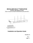
REVOLABS EXECUTIVE HD™ Wireless Microphone System Models: 01-HDEXEC, 01-HDEXEC4, 03-HDEXECEU, 03-HDEXEC4EU 03-HDEXECCN, 03-HDEXEC4CN, 03-HDEXECJP & 03-HDEXEC4JP Installation and Operation Guide © 2009 REVOLABS, INC. All rights reserved. No part of this document may be reproduced in any form or by any means without express written permission from Revolabs, Inc. Product specifications are subject to change without notice. Revolabs Executive HD™ Manual 01-HDEXECMAN-PAP-11 MARCH 2012 (Rev 2.2) Contents Safety and General Information .................................................................................................................... 4 FCC Notice to Users ................................................................................................................................. 4 IMPORTANT NOTE: Federal Communications Commission (FCC) Radiation Exposure Statement ..... 4 Professional Installation Recommended .................................................................................................. 4 Industry Canada Notice to Users .............................................................................................................. 4 Restricted use with certain medical devices ............................................................................................. 4 Export Law Assurances ............................................................................................................................ 4 European Compliance .............................................................................................................................. 5 Standards to which Conformity is declared: ............................................................................................. 5 WEEE Notification: ................................................................................................................................... 5 2003/11/EC & 2002/95/EC ―RoHS Compliance Directive‖: ...................................................................... 5 Introduction.................................................................................................................................................... 6 System Components ................................................................................................................................ 6 Installing the Revolabs Executive HD ™ Base Station ................................................................................. 7 Controls and Connections: ....................................................................................................................... 8 TM Configuring the Executive HD Base Station .............................................................................................. 9 TM Using Multiple Revolabs Executive HD Systems Together .................................................................. 9 Using the Rear Panel Configuration DIP Switches ................................................................................ 11 Using the Revolabs HD Control Panel Software .................................................................................... 11 Using the Serial Control Processor (RS-232 or IP) ................................................................................ 18 Using the Base Station Front Panel Display........................................................................................... 24 Revolabs HD Microphones and HD Microphone Adapters ......................................................................... 25 Using the HD Wearable Wireless Microphones ..................................................................................... 25 Using the HD Omni-Directional Tabletop Wireless Boundary Microphones .......................................... 27 Using the HD Directional Tabletop Wireless Boundary Microphones .................................................... 28 Using the HD XLR Microphone Wireless Adapter .................................................................................. 29 Using the HD Wireless Adapter for Countryman Microphone ................................................................ 30 Pairing Wireless Microphones to Base Station....................................................................................... 31 Revolabs Executive HD Charger Base ....................................................................................................... 32 Power Module ......................................................................................................................................... 33 Charging the Microphone Batteries ........................................................................................................ 33 TM Updating the Revolabs HD Firmware ...................................................................................................... 33 Revolabs Executive HD ™ Indicator LEDs ................................................................................................. 35 Warranty ...................................................................................................................................................... 36 Specifications .............................................................................................................................................. 37 Safety and General Information Please read the following information to ensure safe and efficient use of your Revolabs system. FCC User Information FCC ID: T5V01HDEXEC Revolabs Executive HD™ Base Station FCC ID: T5V01HDEXEMIC Revolabs Executive HD ™ Microphone FCC Notice to Users Users are not permitted to make changes or modify the equipment in any way. Changes or modifications not expressly approved by Revolabs, Inc. could void the user‘s authority to operate the equipment. This device complies with Part 15 of the FCC Rules. Operation is subject to the following two conditions: (1) this device may not cause harmful interference, and (2) this device must accept any interference received, including interference that may cause undesired operation. IMPORTANT NOTE: Federal Communications Commission (FCC) Radiation Exposure Statement This equipment complies with FCC radiation exposure limits for an uncontrolled environment. Professional Installation Recommended This product should be professionally installed. Industry Canada Notice to Users Operation is subject to the following two conditions: (1) This device may not cause interference and (2) This device must accept any interference, including interference that may cause undesired operation of the device IC: 6455A-01HDEXEC Revolabs Executive HD™ Base Station IC: 6455A-01HDEXEMIC Revolabs Executive HD ™ Microphone Restricted use with certain medical devices Hearing Aids Some devices may interfere with some hearing aids. In the event of such interference, you may want to consult with your hearing aid manufacturer to discuss alternatives. Other Medical Devices If you use any other personal medical device, consult the manufacturer of your device to determine if it is adequately shielded from RF energy. Your physician may be able to assist you in obtaining this information. Export Law Assurances This product is controlled under the export regulations of the United States of America and Canada. The Governments of the United States of America and Canada may restrict the exportation or re-exportation of this -4- product to certain destinations. For further information contact the U.S. Department of Commerce or the Canadian Department of Foreign Affairs and International Trade. The use of wireless devices and their accessories may be prohibited or restricted in certain areas. Always obey the laws and regulations on the use of these products. 01-HDEXEC and 01-HDEXEC4 (4 & 8 channel systems respectively) North America UPCS Usage Restriction Due to the UPCS frequencies used, this product is licensed for operation only in the United States of America and Canada. 03-HDEXECEU and 03-HDEXEC4EU (4 & 8 channel systems respectively) European Union Usage Restriction Due to the DECT frequencies used, this product is licensed for operation only in the European Union countries. European Compliance This equipment has been approved in accordance with Council Directive 1999/5/EC ―Radio and Telecommunications Terminal Equipment‖. Conformity of the Equipment with the guidelines below is attested by the CE mark. Model Numbers: 03-HDEXEC4EU-NM Executive HD System, 4-Channel, w/o mics 03-HDEXECEU-NM Executive HD System 8-Channel, w/o mics 03-HDEXEMICEU-11 HD Microphone, RF-Armor™ Wearable* 03-HDTBLMICEU-OM-11 HD Microphone, RF-Armor™ Tabletop, Omni-directional* 03-HDTBLMICEU-DR-11 HD Microphone, RF-Armor™ Tabletop, Uni-directional* 03-HDXLRMICEU-11 HD Microphone, Dynamic XLR Wireless Adapter for Handheld* 03-HDCOMANEU-11 HD Microphone, Countryman Wireless Adapter Standards to which Conformity is declared: RF EMC ETSI EN 301 406 V 1.4.1 03/2001 ETSI EN 301 489-6 v1.2.1 (2002-04) Safety ETSI EN 60950 (2006 +A11) WEEE Notification: The Waste Electrical and Electronic Equipment (WEEE) directive (2002/96/EC) is intended to promote recycling of electrical and electronic equipment and their components at end of life. 2003/11/EC & 2002/95/EC ―RoHS Compliance Directive‖: The products referenced herein are in compliance with the EU directive 2003/11/EC and EU directive 2002/95/EC. -5- Introduction Congratulations on your purchase of a Revolabs digital wireless microphone system! This system utilizes 1.9 GHz DECT technology, and high band-width audio from multiple wireless microphones, enabling clear, reliable, un-tethered communications in recording, audio/video conferencing, speech recognition, VOIP communications, sound reenforcement as well as many other environments requiring clear audio capture. The Revolabs Executive HD ™ Wireless Microphone System has 14kHz audio performance, maximum microphone density and user interface/control including an Ethernet interface. The Executive HD system is a unique marriage of innovative technology and ergonomic design, employing Multi-Carrier Time Division Multiple Access and Time Division Duplex (MC/TDMA/TDD) radio transmissions both to and from the microphone. This technology allows the microphones to co-exist with other wireless products operating at different frequencies such as wireless LANs (802.11b,g&n), and includes digital encryption technology to ensure secure communications. System Components Depending on which system you’ve purchased, your Revolabs Executive HD ™ System packages contain the following: Rack mountable 4 or 8 channel Base Station Microphone Charger Base & Power Supply HD wireless microphones, (earpieces and lanyards with wearable microphone only). The Base Station houses the processor and one end of the wireless connection. It features either two (4 Mic system) or four (8 Mic system) diversity antennae and offers individual line-level or mic-level audio in/out for each microphone channel. This allows for external audio processing such as: -6- Mixing Acoustic echo cancellation (AEC) Feedback elimination Level control Equalization Noise cancellation The system is designed to optimize audio capture/reproduction by providing: Consistent audio input from all participants Minimum room noise Mute control Wireless encryption Automatic channel selection Full duplex audio. The Charger Base stores and charges the wireless microphones when not in use. The Charger Base also serves as a programming station for the microphones, should firmware updates to the microphones be required. Installing the Revolabs Executive HD ™ Base Station The Revolabs Executive HD ™ Base Station, shown below in front and rear panel views, manages wireless audio signal processing, pairing, and muting between the Revolabs microphones and the Base Station. Front View 1 2 5 3 Rear View 6 4 11 7 8 10 12 13 14 9 -7- Controls and Connections: 1. Channel LED indicators: Displays microphone mute and pairing states. 2. Diversity Antenna: One or two sets (4 channel or 8 channel). 3. Pairing Push Buttons: For pairing microphones to Base Station. 4. Two Line LCD Display for front panel operation, command and control. 5. Navigation Buttons for menus on front panel LCD interface. (See Section Using the Base Station Front Panel Display) 6. On/Off Switch: Powers up unit. 7. Power In Receptacle (100-240 VAC). 8. Ethernet Port 9. System Reset Button 10. Mini-Phoenix Connector: Multiple Base Station (BUS) synchronization connection. 11. RS-232 Serial Interface, DB9 (see Section Using the Serial Control Processor (RS232 or IP) 12. Base station status LED‘s (see Section Revolabs Executive HD ™ Indicator LEDs) 13. Configuration DIP Switches (see Section Using the Rear Panel Configuration DIP switches) 14. Mini-Phoenix Connectors: Balanced Audio in and out connections (4 or 8 channels, in and out). The Revolabs Executive HD ™ Base Station is designed to be installed into a standard 19‖ AV rack using the attached rack ears. To Install the Base Station: 1. Plug the power cord into an appropriate outlet. 2. Turn the fuse-protected power switch on the back panel to ―RESET‖. The LCD on the front panel will illuminate. 3. Attach the diversity antennas (2 or 4 SMA female connectors). -8- Revolabs Executive HD™ Audio Connections There are (8) 3.5mm mini-Phoenix inputs and (8) 3.5mm mini-Phoenix outputs on the back panel of the unit (four on the 4-channel system) providing access to each channel‘s audio signal. The provided mini-Phoenix connectors are designed for easy wiring. The three terminals (from left to right) correspond to positive +, negative -, and shielded ground . To connect audio In/Out on the Base Station 1. 2. 3. 4. Use the screws on top of the connector to first loosen the terminals. Insert an appropriate 3-conductor cable (2 conductors and shield) into the terminals. Tighten the screw to secure the cable. Push the connector onto the pins centered under the desired input or output port until firmly secured. The microphone output connectors need to be attached to the line-level (0dBu) input connectors of an audio mixer. PHANTOM POWER MUST BE OFF. PHANTOM MAY CAUSE DAMAGE TO THE BASE STATION. The Base Station input connectors (also 0dBu) may then be attached to mixer channel outputs. Because the system is full-duplex, the input connections provide the ability to hear program audio using a 2.5mm earpiece attached to the microphone (supplied with the wearable microphone). Depending on the application, it is possible to feed a single mixed channel back to all earpieces or, alternatively, each user can receive a separate and unique channel. This would allow for translation, personal hearing assistance or other services to be incorporated into an application. Configuring the Executive HDTM Base Station Each Revolabs Executive HDTM Base Station must be configured properly prior to use. Accurate configuration is dependent on several variables such as: 1. 2. 3. 4. 5. How many Executive HDTM systems are being used together in proximity? What type of 3rd party mute control is being used? How large is the room? Is Line Level or Mic Level signal required? How do the mic mutes need to function? Once these questions are answered, accurate configuration of the Executive HD base can be achieved using a combination of the following methods. Using Multiple Revolabs Executive HDTM Systems Together If more than one Revolabs Executive HD ™ Base Station is used in an area, each unit needs to be interconnected with a synchronization (BUS) cable using a standard 3.5mm mini-Phoenix connector and any 26AWG or better, shielded cable. The maximum distance from the Primary unit to any Secondary device must not exceed 300‘ (90 meters). In addition, DIP switch #1 needs to be adjusted on one or more of the units to represent the ‗Primary‘ and ‗Secondary‘ devices. -9- The three terminals of the BUS connector should be wired in parallel via either a daisy chain connection or terminal block split. The three contacts of the phoenix connector are as follows from left to right. 1. Sync 2. Master Mute 3. Ground Set one Base Station as the Primary device by putting DIP switch #1 to the ‗Off‘ position. The other units must be set as Secondary devices by putting DIP switch #1 to the ‗On‘ position. In this configuration, the Primary device manages the entire system, distributing microphone transmission across available channels to maintain frequency integrity, and coordinating system muting. Primary (DIP switch 1, Off – default): This designates the Base Station as the master control unit. Secondary (DIP switch 1, On): Additional base stations to be used in the same area must be connected via the BUS and be set to REMOTE mode to ensure synchronization of timing clocks between bases in order to prevent interference. Primary (DIP#1 –off) Secondary (DIP#1 –on) Secondary (DIP#1 –on) 3-wire BUS cable Note: Whenever a DIP switch is toggled, the base unit should be reset, or the power should be cycled for the switch setting to be registered. Warning: The switch must be in the „Primary‟ position for a single Base Station system, which is the factory default setting. Microphones will not function if the switch is in the „Secondary‟ position and no „Bus‟ cable is connected. The maximum number of microphone channels within a 300‘ (90 meter) radius in the Americas or Japan is 16 channels (High Definition mode) or 32 channels (Max Density mode). The maximum number of channels within a 300‘ (90 meter) radius for a EU or CN frequency system is 24 channels (High Definition mode) or 40 channels (Max Density mode). (See Section Using the Revolabs HD Control Panel Software) Note: Using Revolabs Executive HD systems in the same area(s) without the bases connected via the BUS will result in interference Warning: Using the maximum number of Revolabs HD Microphones in a given will occupy 100% of the available RF bandwidth. Any other wireless device operating in the same frequency could cause significant interference with the Revolabs HD Microphones. It is recommended that no other DECT or DECT 6.0 products be used within operational range of the Executive HD system(s). - 10 - Using the Rear Panel Configuration DIP Switches off on 12345678 1 – Operation Mode - Primary (off)/Secondary (on) Used when connecting several base stations together for operation in the same area. One system must be set to ‗Primary‘, and all others must be set to ‗Secondary‘. 2 - future use 3 - future use 4 – Audio Output Level - Line (off)/Mic (on) This controls the output audio level on all audio output connectors. Line level audio out (default) refers to an output signal voltage of ~0 dBu, and a Mic Level output signal level is ~-40 dBu. 5 - future use 6 - future use 7 - future use 8 - future use Using the Revolabs HD Control Panel Software A software program with graphical user interface is available for accessing control settings and realtime status of Revolabs Executive HD Microphone Systems. A detailed description of how to use this tool is described below. 1. Download the Revolabs HD Control Panel software from www.revolabs.com/downloads and install onto a PC running Windows 2000, NT, Vista or 7. 2. Connect the PC to the same network as the Base Station via either an Ethernet Crossover Cable, or network switch. 3. If no DHCP server is present, set the fixed IP on the PC to a similar IP address as the one displayed on the Base Station front panel display by changing the last bank of numbers in the IP address. (192.169.1.xxx) 4. Launch the Revolabs HD Control Panel program. 5. Select ‗Scan Network‘ from the ‗System‘ menu or hit the F5 key, and the HD Control Panel will automatically find and display any Revolabs Executive HD base stations visible on the network (the program cannot see through firewalls, etc.). 6. Select the devices needing to be configured and click ‗OK‘ Revolabs HD Gold Control Panel Each Revolabs Executive HD Base Station comes standard with the HD Control Panel, which includes a limited group of controls and features. The Revolabs HD Gold Control Panel requires a 16 digit ‗unlock code‘ to access the additional features and functionality for each Executive HD Base Station. The HD System MAC address shown on the front LED panel of the Base Station is required to receive the unlock code. Each unlock code is tied directly to a specific MAC address and therefore, a specific system. The HD Gold Control Panel unlock code is available by purchasing a Revolabs Service Plan at the time of the system purchase, or may be purchased separately for each - 11 - system. The Revolabs HD Control Panel can operate with either a locked or unlocked Executive HD Base Station. When the HD Control panel is connected to an unlocked Executive HD Base Station, the Gold features will then appear on the screen and be controllable by the user. All features mentioned below with a ‗*‘ after them are only part of the HD Gold Control Panel. Configuration Settings The Revolabs HD Control Panel controls all of the Executive HD Base Station configuration settings. Some, but not all, of the configuration settings can also be controlled from the Base Station front panel display. All configuration settings are located either in the ‗Config‘ tab of the device window or on the HD Control Panel menus. File – Record Events: The ‗Record Events‘ option of the ‗File‘ menu will record the activity of the Base Station and microphone chipsets. This file can only be read by Revolabs technical support. This feature should not be used without the recommendation and support of a Revolabs engineer. System - Scan Network: The ‗Scan Network‘ option of the ‗System‘ menu will search the connected Ethernet network for all connected HD Base Stations. A pop-up ‗Equipment List‘ will show all discovered devices and allow the connection to the selected Base Station(s). Once connected to a Base Station, the HD Control Panel will open a device tab for each Base Station. - 12 - Note: If the „Equipment List‟ does not appear after a network scan has been performed, no devices or network connections were found or the connection is not configured correctly. System - Set Box Name: A Box Name may be assigned as a Network ID for each device. This name will be displayed both on the front screen of the Base Station along with the IP address and on the device tab in the HD Control Panel Software. The Box Name can be set by selecting ‗Set Name‘ from the ‗System‘ menu. The corresponding pop-up will show the current box name, which can be changed. The default box name is the device IP address. System - Set Telnet Password: A Telnet Password may be assigned for logging into a Base Station. Once a Telnet Password is assigned, it must be entered to communicate with the Base Station over Ethernet via the HD Control Panel Software. The Telnet Password can be set by selecting ‗Set Password‘ from the ‗System‘ menu. The corresponding pop-up will show if a password has been set and will allow the password to be changed. There is no default password set. System - Set IP Configuration: If the Executive HD Base Station is set to DHCP mode and no DHCP server is found, the Base Station will auto-populate its own IP address and display it on the front panel display. This automatic IP address will change every time the Base Station is rebooted for as long as DHCP is enabled. If a fixed IP is desired, a fixed IP can be assigned to the Base Station. The IP Configuration can be set by selecting ‗Set IP Config‘ from the ‗System‘ menu. The corresponding pop-up will show the current IP configuration and allow the configuration to be changed. - 13 - Note: Changes to the IP Configuration will take place once the Base Station‟s power is cycled. System – Enable Gold: Each Executive HD Base Station has two sets of features. There are the standard features that are included with the system and the Gold features that require a 16 digit unlock code to enable the addition Gold features. You can use the unlock code to enable the Gold features by select ‗Enable Gold‘ from the ‗System‘ menu. Note: An unlock code can be requested by providing the system MAC address shown on the front LED panel and the necessary purchase information through www.revolabs.com/downloads Firmware - Update Firmware: Executive HD Systems are field upgradable for the firmware portion of the Base Station and Microphones. The firmware must be sent to both the Base station and Microphones using the HD Control Panel program. (See Updating the Revolabs HD Firmware for more information) Tools – Express Pair: The ―Express Pair‖ tool allows all of the HD microphones, in an Executive HD System, to be paired simultaneously via the HD Control Panel. Selecting ―Express Pair‖, while connected to an Executive HD Base Station via Ethernet, and an Executive HD Charger Base via USB, will pair the microphones in the connected Charger Base to the selected Base Station. A notification will appear at the end of the process to confirm pairing success. Note: A 4-channel Charger must be used with a 4-channel Base Station and an 8-channel Charger must be used with an 8-channel Base Station for an express pair to be successful. Tools – Mic Pop-Ups:* The user can choose to have Pop-Up notifications inform them of when a microphone is out of range. Config - External Control Processor: The Serial Control Processor allows the use of third party control system or DSP to monitor and/or control the Executive HD Base Station and Microphones. (See Using the Serial Control Processor) - 14 - Config - Audio Mode: There are two audio modes to choose from when using an Executive HD System. ‗High Definition‘ mode (default), which provides 50Hz-14KHz audio, and ‗Max Density‘ mode, which provides 50Hz12KHz audio. While ‗High Definition‘ mode provides the highest audio bandwidth, ‗Max Density‘ mode provides the ability to use more mics in a given area. Note: A change to the Base Station Audio Mode will result in an automatic system reboot. Config - Redundancy: Redundancy allows the HD base station to use back channels to mitigate interference and prevent 3 rd party wireless RF from interfering with the Revolabs system. Turning off Redundancy will reduce the audio latency by 5ms but will render the system susceptible to RF interference when 3 rd party wireless RF devices, operating in the same RF band, are present. Note: A change to the Base Station Redundancy Mode will result in an automatic system reboot. Config – Power Scaling: Power scaling allows the base station and microphones to automatically change their transmit power levels maximizing the RF band and reducing the possibility of interference between multiple Revolabs systems. Turning power scaling off fixes the base station and microphone transmit power levels to that set in the ‗transmit power‘ setting on the config section of the HD Control Panel providing the system with RF priority when used in proximity of other 3 rd party wireless RF devices operating in the same RF band. Config - Transmit Power: The Transmit Power of the Base Station can be adjusted to help reduce the operational radius of an Executive HD System in order to prevent interference from other Revolabs products, or from other devices operating in the same frequency. The options for transmit power are 0db-25db with 10db as the default setting. This configuration setting can also be controlled using the Base Station front panel display. Config – Mics Unmuted at Startup: By default the mics go into a muted state when they are removed from the charger. This is done to prevent handling noise as the microphone is placed into position. By selecting ‗Mics Unmuted at Startup‘, the mics will go into an unmuted state when removed from the charger. Config - Tabletop Mute: The Executive HD System provides two options for microphone mute performance. The default option allows each microphone to have its own individual mute capabilities as well as a Master Mute function that will lock all mics into a muted state until the function is disabled. The Master Mute can only be triggered by a control system via RS-232 or Ethernet. The second option allows all tabletop microphones to act as a Master Mute, leaving only the Wearable microphones, Countryman and XLR adapters with individual mute capabilities. Muting any table top style microphone will cause all microphones in the system to mute until another tabletop microphone mute button is pressed. Un-muting a tabletop microphone will cause all tabletop microphones to un-mute and will return all Wearable microphones, Countryman and XLR adapters to their previous state of individual mute capability. The ‗Tabletop Master Mute‘ mode can be activated by selecting the option in the ‗config‘ tab of the device window. - 15 - Note: When a Master mute is enabled either through the control system or by using Tabletop Master Mute mode, all Base Stations connected with a bus cable and assigned to the same mute group will be affected. Config - Lock Front Panel: The Front Panel display can be locked to keep the front panel controls from changing any configuration settings. The ‗Lock Front Panel‘ mode can be activated by selecting the option in the ‗config‘ tab of the device window. Config – Base Pairing Lock:* Paring lock disables the functionality of the pairing buttons on the front of the HD Base Station preventing the user from pairing microphones to the system. Note: Selecting the „Pairing Lock‟ function will automatically reboot the HD base station. Config – Audio Zone: Each Executive HD base station that is bussed together, using the 3 conductor BUS cable, can communicate mute commands and serial query commands over the BUS. Only systems assigned to the same ‗Mute Group‘ will be able to communicate together regardless of how many systems are connected via the same BUS cable. Each base station within a single ‗Mute Group‘ must be assigned a different ‗Box ID‘ with the master system being assigned the ‗Box ID‘ of ‗0‘. Any two systems which are assigned the same ‗Box ID‘ within the same ‗Mute Group‘ will not function. Status Monitoring The Revolabs HD Control Panel monitors the Executive HD Base Station and Microphones. All status monitoring is located in the ‗Monitor‘ tab of the device window. - 16 - Monitor – Microphone Lock:* Each microphone has individual lock capabilities. By turning on the lock for a specific microphone, the microphone mute button will deactivate leaving the user without the ability to individually control the microphones mute status at the microphone. However, the HD Control Panel Software, as well as any connected Serial Control Processor, will still have the ability to control and monitor all locked microphones. Note: A microphone lock is stored in the Base Station. If a new microphone is paired to a locked channel, that microphone will then be locked as well. The same goes for a locked microphone that is paired to an unlocked channel, that microphone will then be unlocked. Monitor – Microphone Mute:* Each microphone has individual mute capabilities. The HD Control Panel Software provides the user the ability to mute and unmute a microphone from their PC. These mute controls will always remain synchronized to the actual state of the microphone. If the microphone state is changed through another method, the mute controls will display that change. Monitor – Microphone Gain:* Each microphone has an individual gain fader. This fader provides +/- 10dB of gain in 5dB increments. The microphone gains are stored in the Base Station and will be applied to any microphone paired to that channel. Monitor - Microphone Status:* This provides the current status for the microphone paired to each channel. The status can read any of the following states: OFF ON CHRG OUT = = = = Microphone is has been turned off Microphone is on and operational Microphone is in the Charging Base Microphone is out of range and cannot communicate Monitor - Microphone Type: This provides the current type for the microphone that is paired to each channel. Monitor - Microphone Version: This provides the current firmware version for the microphone that is paired to each channel. Note: The microphone firmware version must match the Base firmware version for the system to function properly. A mismatch may result in no audio from the microphones. Monitor - Microphone Battery: This provides the current battery level for the microphone that is paired to each channel and active. The value changes in 12.5% increments and represents the bottom of the range the battery is in. Therefore a value of 87% means that the battery level is between 87%-100%. Monitor - Pairing:* This provides the ability to activate pairing mode for the respective base station channel. It also provides the pairing status of any base station channel already in pairing mode. The pairing controls will work regardless of the state of the ‗Base Pairing Lock‘ - 17 - Monitor – Versions: This window provides the current firmware versions found in the Base Station. Monitor – DIP Switches: This displays the current state of the base station DIP switches. When a DIP switch is in the ‗OFF‘ position the DIP function will remain ―greyed out‖. When a DIP switch is in the ‗ON‘ position, the functionality of that DIP switch will change to BLACK to indicated that the feature is active. Using the Serial Control Processor (RS-232 or IP) The Serial Control Processor allows the use of a third party control system or DSP to monitor and/or control the Executive HD Base Station and Microphones. The Executive HD Base Station must be configured for the correct ―Serial Control Processor‖ using the Revolabs HD Control Panel software. DB9 Pin-out: Pin 2 = Rx Pin 3 = Tx Pin 5 = GND Pin 7 = RTS Pin 8 = CTS Using the Executive HD Base Station with a Control System The Executive HD Base Station is capable of being monitored and controlled via any serial capable control system. The only logic communication that takes place between multiple Base Stations, via the ‗BUS‘ cable, is ―Master Mute‖ state and global serial queries. Therefore, each Base Station requires its own serial connection to the control system in order to communicate. The ―Control System‖ option must be selected, under the ―External Control Processor‖ drop down menu, in the Executive HD Control Panel software, in order for this configuration to function properly. You must also set the RS-232 or Network settings of the Base Station to match the communication settings of the control system. If ‗Network‘ is the chosen protocol for serial communication, the control system must utilize a ―TCP/IP Server‖ module to communicate to the Executive HD base station. - 18 - When using a control system, the microphone mutes can be configured to ―int. mute‖, which mutes the microphone audio inside of the base station, or ―ext. mute‖, which allows the control system to choose another location for the mute to take place. When ―ext. mute‖ is selected, the microphones will always pass audio no matter their mute state. Note: Both a control system and DSP cannot be connected to a Base Station as a serial control processor at the same time. When using a control system, the DSP control must be done by the control system and not the Base Station. Serial Command & Return Strings: The Serial Strings of an Executive HD Base Station begin with the Argument and terminates with a Carriage Return. The Command String structure is as follows: <Argument> <Command> ch <Channel #> <Value> <CR> All variable changes to the microphone or Base Station will result in a Return String. A Return String will begin with ―val‖ and terminate with a Carriage Return. You will receive a Return String for every value change that has taken place in the microphones or base station including changes that are a result of the Command String sent to the Base Station. The Return String structure is as follows: val <Command> ch <Channel #> <Value> <CR> String Table: The following table represents the serial syntax of the Executive HD system. Any command marked with an asterisk will only function if the Base Station has Gold Enabled by entering that systems unlock code. (See Revolabs HD Gold Control Panel) Argument Command Channel# Value set lock* set mute set mute 1-8 = ch 1-8 A = All Mics 1-8 = ch 1-8 B = All Mics A = Master Mute set gain* 1-8 = ch 1-8 A = All Mics set set pair* pwr* 1-8 = ch 1-8 1-8 = ch 1-8 A = All Mics 0 = Mic Lock Off 1 = Mic Lock On 0 = Unmute Mic 1 = Mute Mic 0 = Master Mute Off 1 = Master Mute On 2 = Master Mute Toggle 0 = 0db Absolute 1 = -0.5db Relative 2 = +0.5db Relative 80-120 = -10db - +10db in 0.5db increments 1 = Activate Pairing 0 = Power Off Microphone set um set tm 0 = UnMute @ Startup Off 1 = UnMute @ Startup On 0 = TableTop Mute Off 1 = TableTop Mute On - 19 - set fp set pair* get lock* get mute get gain* get type* get batt get pair* get get get get get val pair* fp tm um fw lock* val mute 1-8 = ch 1-8 A = Master Mute val val gain* type* 1-8 = ch 1-8 1-8 = ch 1-8 val batt 1-8 = ch 1-8 val pair* 1-8 = ch 1-8 val pair* 1-8 = ch 1-8 A = All Mics 1-8 = ch 1-8 A = Master Mute B = All Mics 1-8 = ch 1-8 A = All Mics 1-8 = ch 1-8 A = All Mics 1-8 = ch 1-8 A = All Mics 1-8 = ch 1-8 A = All Mics 1-8 = ch 1-8 0 = Front Panel Display Lock OFF 1 = Front Panel Display Lock ON 0 = Base Pairing Lock OFF 1 = Base Pairing Lock ON (Mute Lock Status) (Individual or Master Mute Status) (Mic Gain Status) (Mic Type Status) (Mic Battery Status) (Base Pairing Status) (Base Pairing Lock Status) (Base Front Panel Lock Status) (Base TableTop Mute Status) (Base UnMute @ Startup Status) (System Firmware Revisions) 0 = Mic Lock Off 1 = Mic Lock On 0 = Unmuted 1 = Self Muted (TT Master Mute Mode) 2 = Muted 3 = Microphone Off 4 = Microphone Out of Range* 5 = Microphone Charging* 80-120 = -10db - +10db in 0.5db increments 0 = Lapel (Wearable) 1 = Tabletop Omnidirectional 2 = Tabletop Directional 3 = XLR Adapter 4 = Countryman Adapter 0 = empty 1 = 25% 2 = 50% 3 = 75% 4 = 100% 0 = Pairing Inactive 1 = Pairing Active 0 = Base Pairing Unlocked 1 = Base Pairing Locked - 20 - val fp val tm val um val fw 0 = Front Panel Unlocked 1 = Front Panel Locked 0 = TableTop Mute Inactive 1 = TableTop Mute Active 0 = Mic UnMute @ Startup Inactive 1 = Mic UnMute @ Startup Active xxxxxx = xx.xx.xx Channel #: The options for the <Channel#> portion of the serial strings are ―1-8‖ since each Base station can only control up to 8 channels of an Executive HD microphone system. The <channel#> corresponds to the physical channel that the microphone is paired to on the front of each Base Station. A <Channel#> of ―A‖ will control all mics. This command must only be sent to the Base Station that is set to ―Local‖. ―Remote‖ Base Stations will not accept the command. Examples: The following strings would unmute microphone channel 3: Command: set mute ch 3 0 Return: val mute ch 3 0 The following strings would turn on the Master Mute: Command: set mute ch A 1 Return: val mute ch A 1 The following strings would retrieve the battery status of mic 5 @ 100%: Command: get batt ch 5 Return: val batt ch 5 4 Using the Executive HD Base Station with a DSP The Executive HD system is designed to control the mutes of a DSP directly in the event that a control system is not present. The Base Station must be configured for the correct ―Serial Control Processor‖, using the Executive HD Control Panel software, in order to send the mute commands to the DSP. In addition, each DSP model must be configured correctly to receive mute commands. ClearOne Converge & XAP When using the Base Station along with a ClearOne DSP, you must select the corresponding DSP product line from the ―Serial Control Processor‖ menu in the Revolabs HD Control Panel software. You must also set the RS-232 or Network settings of the Base Station to match the communication settings of the ClearOne DSP. The Base Station will only control the mutes of the DSP it is connected to via RS232 or IP. An 8-channel Base Station will control microphone channels 1-8 of the DSP, and a 4-channel Base Station will have the choice of controlling microphone channels 1-4 or 5-8 of the DSP. - 21 - Biamp Audia & Nexia When using the Base Station along with a Biamp DSP, you must select the corresponding DSP product line from the ―Serial Control Processor‖ menu in the Revolabs HD Control Panel software. You must also set the RS-232 or Network settings of the Base Station to match the communication settings of the Biamp DSP as well as select the ‗Audio Channels‘ of the microphones that the Base Station is to simulate.(i.e. 1-8, 9-16, etc.) Each Base station will control the mutes of a ―level block‖, within the DSP programming, using that block‘s instance ID tag. The tags are as follows: Audio Channels 1-8 Audio Channels 9-16 Audio Channels 17-24 Audio Channels 25-32 Audio Channels 33-40 MUTE1 MUTE2 MUTE3 MUTE4 MUTE5 (EU & CN Versions only) - 22 - So for example, if you set the ‗Audio channels‘ for the microphones to 1-8 in the Control Panel, then the Base Station will use the instance ID tag of ―MUTE1‖, and control the first 8 mutes in that fader block. Note: Instance ID tags are case sensitive and must be entered correctly in order to function properly. A “level block” must be used as the method of muting. Polycom SoundStructure When using the Base Station along with a Polycom SoundStructure, you must select the corresponding DSP product line from the ―Serial Control Processor‖ menu in the Revolabs HD Control Panel software. You must also set the RS-232 or Network settings of the Base Station to match the communication settings of the Polycom SoundStructure as well as select the ‗Audio Channels‘ of the microphones that the Base Station is to simulate.(i.e. 1-8, 9-16, etc.) Each Base station will control the mutes of each individual microphone channel, within the DSP programming, using that channel‘s name. The name structure is as follows: Channels 1-8 Channels 9-16 Channels 17-24 Channels 25-32 Channels 33-40 Revo 1 - Revo 8 Revo 9 - Revo 16 Revo 17 - Revo 24 Revo 25 - Revo 32 Revo 33 – Revo 40 (EU & CN Versions Only) - 23 - So for example, if you set the ‗Audio channels‘ range for the microphones to 1-8, in the Control Panel, then the Base Station will use the DSP channel name of ―Revo 1‖ to control mute for the microphone paired to channel 1 of the Base Station. Note: Channel names are case sensitive and must be entered correctly to function properly. Using the Base Station Front Panel Display The Base Station has four or eight indicator LEDs (one for each channel) and pairing push buttons on the front panel. (See Section Pairing Wireless Microphones to Base) When the LED is flashing GREEN or RED, that channel is active and connected to a wireless microphone (GREEN is for live audio, RED is for muted). When the LED is OFF, the channel is inactive (the microphone is out of range or turned off). The LCD and menu buttons are designed to provide the system installer the ability to access certain configuration settings directly from the front panel instead of having to use the Revolabs HD Control Panel software. Navigation up Navigation down Return to Main Menu Select Item Backup one menu level The user can choose to have the front panel display the current firmware, the current IP address and box name, or the MAC address of the Base Station during normal operation. During a firmware upload, the front panel will display the current progress of the firmware upload. The following is a list of the configuration settings that can be changed using the front panel display controls. 1. Select High Definition or Max Density modes 2. Select the Transmit Power of the Base Station 3. Select Table Top Mute mode - 24 - 4. 5. 6. 7. 8. Change the Low Pass Filter Select DHCP or Fixed IP modes Select Redundancy Mode Select Power Scaling Mode Select Mute Group Note: Switching between High Definition, Max Density, and Redundancy modes will cause the Base Station to automatically reboot. A change in the IP configuration will require a power cycle to take effect. Revolabs HD Microphones and HD Microphone Adapters Use any of five microphones with your Revolabs HD ™ System: Revolabs HD Wearable Wireless Microphone Revolabs HD Omni-directional Tabletop Wireless Boundary Microphone Revolabs HD Uni-directional Tabletop Wireless Boundary Microphone Revolabs HD Universal Wireless Adapter for Handheld Microphones Revolabs HD Wireless Adapter for Countryman Microphones Using the HD Wearable Wireless Microphones The Revolabs HD Wearable Microphones, shown in the following figure, are paired to the Base Station and can be worn on the user‘s shirt pocket, lapel or on a lanyard. They provide high quality full duplex audio between each user and the conferencing or audio system. 6 5 1 1. 2. 3. 4. 5. 6. 4 2 3 Earpiece jack — accepts the 2.5mm plug for the earpiece. Charging port — docks to Revolabs HD Charger Bases. Pocket clip — also used to attach microphone to a lapel, blouse or lanyard. Mute Button — press to mute, un-mute and pair microphone. Acoustic Cover — protects delicate microphone element (non-removable). LED display — visual status for mute, un-mute, and pairing. Note: Microphones in new systems must be paired to the Base Station with each microphone assigned to a unique channel on the base unit. See pairing instructions below. - 25 - Revolabs HD Wearable Microphones turn on and mute automatically when removed from Charger Base, to reduce noise while being attached. To use the HD Wearable Microphone: 5. Remove the microphone from the Charger Base. 6. Attach the microphone to clothing or to a lanyard, position microphone just above the sternum or breastbone, within 6 - 12 inches (15 – 30cm) from the mouth is recommended. Make sure microphone is attached securely with the microphone LED indicator pointed up toward mouth. 7. With the microphone in the wearing position, un-mute the microphone by pressing and releasing the Mute button (confirm by a flashing GREEN LED). If the volume is too low, move the microphone closer to the mouth. 8. To turn microphones off, return the microphone unit to the Charger Base or press and hold the Mute button for ~10 seconds until the LED turns solid RED then release button. If the microphones are moved out of range of the Base Station (~300 feet or 91 meters) the connection will be dropped (LED flashes all red, green, yellow) and the microphone will mute. After 15 seconds the microphone will beep 5 times, and will continue beeping every 30 seconds to remind the user to return the microphone to the conference room. If the microphone is moved back into range within 15 minutes the connection will automatically be re-established to its original state, and the beeping will cease. If not, the microphone will turn off. Adjusting the Volume on the Wearable Microphone Earpiece To change the volume on the Wearable microphone earpiece, use the dial on the earpiece wire. Turning the dial towards the earpiece, as shown in the figure, will increase the volume, and turning the dial towards the microphone will decrease the volume. Use the attached clothing clip to secure the earpiece wire. - 26 - Using the HD Omni-Directional Tabletop Wireless Boundary Microphones The HD Omni-directional Tabletop Wireless Boundary Microphones enable multiple conference attendees to use a single microphone. 360 º pickup pattern 1 2 3 6 5 4 1. 2. 3. 4. 5. 6. LED display — visual status for mute, un-mute, and pairing. Mute button — press to mute, un-mute and pair microphone. Audio jack — accepts a 2.5mm plug. Charging port — docks to Revolabs HD Charger Bases. Rubber feet — non-slip, vibration absorbing pads. Acoustic Cover — protects delicate microphone element (non-removable). To use the HD Omni Tabletop Microphone: 9. Remove the microphone from the Charger Base to turn on and automatically mute the mic. (indicated by a flashing RED LED) 10. Omni Tabletop microphones can be centered on the table within 2 to 6 feet (0.6 to 2m) away from people speaking and do not need to be pointing any particular direction because they pick up sound from all directions. It is always better to be as close to the person speaking as possible, but avoid placing the microphone where it might be blocked by equipment or paperwork. Avoid placing microphones too close to an audio or video conference speaker to avoid echoes. Make sure that the microphone is always placed lying on its rubber feet atop a flat surface. 11. With the microphone in position on the table, un-mute the microphone by pressing and releasing the Mute button (confirm by a flashing GREEN LED). 12. To turn microphone off, return the microphone unit to the Charger Base or press and hold the Mute button for ~10 seconds until the LED turns solid RED and release button. - 27 - If the microphones are placed too far from the Base Station (~300 feet or 91 meters) the connection will be dropped (LED flashes all colors) and the microphone will mute. After 15 seconds the microphone will beep 5 times, and will continue beeping every 30 seconds to indicating it‘s out of range. Move the microphone closer to the Base Station and the connection will automatically be reestablished to its original state, and the beeping will cease. If not, the microphone will continue beeping until it turns off in about 15 minutes. Using the HD Directional Tabletop Wireless Boundary Microphones The HD Tabletop Wireless Microphone, shown below, is designed to provide optimum coverage when placed on a conference room table in front of one or two people. Pickup patter n 45 45 º º 6 5 1 2 1. 2. 3. 4. 5. 6. 3 4 LED display — visual status for mute, un-mute, and pairing. Rubber feet — non-slip, vibration absorbing pads. Audio jack — accepts a 2.5mm plug. Charging port — docks to Revolabs HD Charger Bases. Mute button — press to mute, un-mute and pair microphone. Acoustic Cover — protects microphone element (non-removable). To use the HD Directional Tabletop Microphone: 13. Remove the microphone from the Charger Base to turn on and automatically mute the mic. (indicated by a flashing RED LED) 14. Directional Tabletop microphones should be located on the table with the acoustic cover pointed toward the users, trying to keep the microphone 2 to 6 feet (0.6 to 2m) from the target person or two. The pick-up pattern for this directional microphone is ~+/- 45º to either side of directly in front of the microphone. It is always better to be as close to the person speaking as possible, but avoid placing the microphone where it might be blocked by equipment or paperwork. Avoid placing microphones too close to an audio or video conference speaker to avoid echoes. Make sure that the microphone is always placed lying on its rubber feet atop a flat surface. Refer to diagram below: - 28 - 15. With the microphone in position, un-mute the microphone by pressing and releasing the Mute button (confirm by a flashing GREEN LED). 16. To turn microphone off, return the microphone unit to the Charger Base or press and hold the Mute button for ~10 seconds until the LED turns solid RED and release button. If the microphones are placed too far from the Base Station (~300 feet or 91 meters) the connection will be dropped (LED flashes all colors) and the microphone will mute. After 15 seconds the microphone will beep 5 times, and will continue beeping every 30 seconds to indicating it‘s out of range. Move the microphone closer to the Base Station and the connection will automatically be reestablished to its original state, and the beeping will cease. If not, the microphone will continue beeping until it turns off in about 15 minutes. Using the HD XLR Microphone Wireless Adapter The HD Wireless XLR Adapter for Handheld Microphone, shown in the following figure, connects to a handheld dynamic microphone for wireless freedom during open mic meetings, Q&A sessions, classrooms, etc. 5 4 3 1 1. 2. 3. 4. 5. 2 Audio Out port — accepts the 2.5mm plug for the earpiece. Charging Port — docks to all Revolabs HD Charger Bases. Mute button — press to mute, un-mute and pair microphone. LED display — visual status for mute, un-mute, and pairing. XLR Female connector — balanced audio for dynamic microphones. To use the HD Universal Wireless Adapter: 17. Remove the Microphone Adapter from the Charger Base. The adapter turns on and mutes automatically when removed from Charger Base (flashing RED LED). The XLR Microphone Adapter is attached to a standard dynamic microphone to convert it from a wired microphone to a wireless microphone (see following figure). - 29 - Note: The Adapter does not provide phantom power or bias current so it cannot be used with condenser or electret microphones. 18. With the microphone attached, un-mute the Adapter by pressing and releasing the Mute button (confirm by a flashing GREEN LED). Note: to use. If the microphone has an on-board mute switch, this switch must also be un-muted prior 19. To turn the Adapter off, return the microphone unit to the Charger Base or press and hold the Mute button for ~10 seconds until the LED turns solid RED then release button. Important: Always remove the microphone from the Adapter by pressing the latch switch and separating the parts before returning the Adapter to the Charger Base. If the Adapter is moved too far from the Base Station (~300 feet or 91 meters) the connection will be dropped (LED flashes all colors) and the audio will mute. After 15 seconds the microphone will beep 5 times, and will continue beeping every 30 seconds to indicate that it is out of range. Move the XLR Adapter closer to the Base Station and the connection will automatically be reestablished to its original state, and the beeping will cease. If not, the XLR Adapter will continue beeping until it turns off in about 15 minutes. Using the HD Wireless Adapter for Countryman Microphone The HD Wireless Adapter for Countryman Microphones, shown in the following figure, is connects to a Countryman microphones for wireless freedom for broadcasting applications with no bulky equipment, such as a belt pack or batteries. 5 4 1 3 2 1. Audio Out port — accepts the 2.5mm plug for the earpiece. 2. Charging Port — docks to all Revolabs HD Charger Bases. 3. Mute button — press to mute, un-mute and pair microphone. - 30 - 4. LED display — visual status for mute, un-mute, and pairing. 5. TA4M connector — connects to Countryman microphone cable. To use the HD Wireless Adapter for Countryman Microphone: 20. Remove the Microphone Adapter from the Charger Base. The adapter turns on and mutes automatically when removed from Charger Base (flashing RED LED). The Microphone Adapter is attached to a Countryman Microphone with the specific cable designed for Revolabs. The HD Wireless Adapter for Countryman microphone supplies the necessary phantom power specifically for the Countryman microphone. 21. To turn the Adapter off, return the microphone unit to the Charger Base or press and hold the Mute button for ~10 seconds until the LED turns solid RED then release button. Important: Always remove the microphone from the Adapter and separate the parts before returning the Adapter to the Charger Base. If the Adapter is moved too far from the Base Station (~300 feet or 91 meters) the connection will be dropped (LED flashes all colors) and the audio will mute. After 15 seconds the microphone will beep 5 times, and will continue beeping every 30 seconds to indicate that it is out of range. Move the Countryman Adapter closer to the Base Station and the connection will automatically be reestablished to its original state, and the beeping will cease. If not, the Countryman Adapter will continue beeping until it turns off in about 15 minutes. Pairing Wireless Microphones to Base Station Pairing creates a link between the HD wireless microphone and the Base Station, with a unique electronic serial number. When the microphone and Base Station have been previously paired, the mic will automatically try to connect to the same Base Station whenever it is lifted from the Charger Base. Note: Microphones in new systems must be paired to the Base Station with each microphone assigned to a unique channel on the base unit. Remember, microphones are by default muted (flashing RED LED) when they are removed from the Charger Base and the Mute button needs to be pressed to make it ―live‖ (flashing GREEN LED). A microphone that is not paired will be indicated by a cycling RED-GREEN LED pattern. A Base Station channel that is not paired to a microphone will not show any activity on the channel LED (make sure unit is first powered on by observing GREEN backlit front panel display). When channels are paired, both microphone and channel LEDs will flash RED as microphones are removed from the Charger Base and flash GREEN when un-muted. Remember that only one microphone can be paired to any single Base Station channel. ―Express Pair‖ is a tool in the HD Control Panel Software that can be used to pair all the microphones in a Charger Base to a Base Station at the same time. (See: Tools – Express Pair) - 31 - To pair an individual microphone to the Base Station: 1. Turn the microphone OFF (no LED activity). If the microphone is ON, press and hold the Mute button for 10 seconds until the LED turns solid RED then release the button to turn the unit off. (do not release the button when you hear two beeps). 2. Place the microphone unit into pairing mode by holding the Mute button down for seven seconds. The LED will turn solid RED. Release the Mute button. The microphone is now in pairing mode. 3. Within one minute, push and hold the button for the desired channel on the Base Station for seven seconds until the LED turns solid red then release. The LED for that channel will be solid red until pairing starts, as indicated by a quick GREEN flash, then switching to flashing RED on both the microphone and the Base Station (muted audio). Pairing is now complete. Revolabs Executive HD Charger Base When Microphones are not in use, they should be properly inserted into the Executive HD Charger base. It is important to ensure that all system microphones are inserted fully in the base so that charging will occur. While charging in the Charger Base, the Charger Base USB connection may be used to either update HD Microphone firmware or ―Express Pair‖ the microphones to the Base Station. The microphone charging ports are numbered 1-8 from left to right and back to front. Therefore the rear left port is number 1 and the front right port is number 8. Features of the base are shown in the following figure. 1 2 3 4 1. LED indicator — power status indicator. 2. Charger Bays — charges up to 8 Microphones. 3. Mini USB Interface — computer serial interface for firmware upgrades to the microphones (on rear). 4. Power Cord Receptacle — power supply input, 9-24VDC (on rear). - 32 - Note: A 4-channel Charger must be used with a 4-channel Base Station and an 8-channel Charger must be used with an 8-channel Base Station for an express pair to be successful. Power Module The Charger Base requires 9-24VDC power, provided by the AC Adapter. Plug the supplied AC adapter into an appropriate power outlet 110-240 AC, 50-60Hz. The power LED on the Charger Base will illuminate. Charging the Microphone Batteries First-time use — Before using the wireless microphone the first time, charge the batteries in the microphones for eight hours (or overnight) in the Charger Base. Recharging — When the YELLOW LED starts to flash intermittently on the microphone the battery has 30 minutes of charge remaining. Over time (years), batteries gradually wear down and require longer charging times. This is normal. Always return microphones to the Charger Base when not in use. Important: The Lithium Polymer rechargeable batteries that power the microphones are not user serviceable. Please contact Revolabs (www.revolabs.com) or your AV service provider for replacement instructions and to assure the proper disposal method is used. Warning: Never dispose of batteries in a fire because they may explode. Either a solid RED LED (charging) or solid GREEN LED (100% charged) will appear to confirm that the microphone is inserted properly in the Charger Base. The microphones are not transmitting audio to the Executive HD base station while in the Charger Base. In normal use, batteries should fully charge in about 2 hours, but will ―quick-charge‖ to 80% capacity in approximately 1 hour and 20 minutes. Fully charged microphones left in the Charger Base remain solid GREEN. Updating the Revolabs HDTM Firmware Executive HD Systems are field upgradable for the firmware portion of the Base Station and microphones. The firmware must be sent to both the Base station and microphone using the HD Control Panel program. Note: If your Base Station and microphones have different firmware versions, they may not work together. Confirm that your Base Station and microphones are updated before use. Updating the Executive HD Base Station & Microphones The Executive HD Base Station firmware can be changed using the Revolabs HD Control Panel program. You can download the latest firmware at www.Revolabs.com/downloads. The same firmware file can be used for all Revolabs HDTM Products. Communication to the Base Station is done over an Ethernet connection, and communication to the microphones is done through the Charger Base via Mini-USB cable. - 33 - 1. Go to www.Revolabs.com/downloads, download the latest firmware file and save it to your PC. The firmware file must remain in its .zip format in order to function correctly. 2. Connect the Charger Base to your computer using the Mini-USB cable provided. Make sure that the charger is plugged in and powered on and that the microphones are in it. 3. Connect to the Base Station using an Ethernet cable. This can be done via a direct connection to the PC or through a DHCP router or switch. 4. Set your PC IP address. The PC and Base station must be both set to a fixed IP address or both connected to a DHCP router and have DHCP turned on. (See Using the Revolabs HD Control Panel Software) 5. Start the Revolabs HD Control Panel software. 6. Select ‗Scan Network‘ from the ‗System‘ menu. 7. Select the Base Station you which to update and click ‗OK‘ 8. Select ‗Update Firmware‘ from the ‗Firmware‘ menu. 9. Browse to the firmware file on your PC and click ‗OK‘ 10. Select the Base Station that you would like to update. 11. Choose whether you would like to update the base, mics, or both. 12. Select OK and watch the firmware process either on the Base Station front panel display or in the ‗monitor‘ tab in the Revolabs HD Control Panel program. The HD Control Panel will notify you when the process is complete. Note: A Base Station must either be connected to a DHCP server or have a fixed IP address in order to receive a firmware update. A Base Station that is set to DHCP with no DHCP server present will fail in any update attempt. - 34 - Revolabs Executive HD ™ Indicator LEDs The following tables show activities associated with the various states shown by the LEDs: Equipment Use Microphone LED Microphone in Charger Base Microphone not in Charger Base Solid RED Solid GREEN OFF Base Station Channel LEDs OFF OFF OFF Two RED flashes every 1.5 seconds GREEN flash every 1.5 seconds Solid RED Two RED flashes every 1.5 seconds GREEN flash every 1.5 seconds Solid RED Alternating slow GREEN and RED YELLOW flash alternating with GREEN YELLOW flash alternating with two RED flashes Alternating RED, YELLOW, GREEN Alternating slow GREEN and RED GREEN Flashing Rapid RED flashes continuing for more than a few seconds OFF Groups of five rapid RED flashes OFF Meaning Charging in Progress Charging Complete Microphone powered OFF or battery discharged Microphone paired and muted Microphone paired and ―live‖ Pairing mode or confirmation of powering-down. Microphone or channel not paired Microphone low battery (mic live) RED Flashing Microphone low battery (mic muted) OFF Searching for a connection, or out of radio range. The Microphone will try to reestablish the link for about 15 minutes, and then turn off automatically. Radio congestion – it is not possible to make a radio connection because there are already too many nearby users, or there is heavy radio interference. Possibilities include some types of digital wireless devices or other Revolabs installations. Unit is faulty. Contact your AV service provider for advice. - 35 - Warranty Revolabs, Inc. warrants this product to be free of manufacturing defects. Repair or replacement of any defective part or unit (at the discretion of the Seller) will be free of charge for the period defined in the Revolabs Professional Products Limited Warranty. Any attempt by the user to alter the equipment, or equipment damaged by negligence, accident, or Acts of God voids this warranty. The Seller shall not be liable for any consequential damage resulting from the malfunction of this product. Should the user experience unsatisfactory performance from this equipment, contact the Seller to obtain instructions for return, or replacement, as deemed necessary. This warranty is not transferable by the original end user. Complete details and terms of the Limited Warranty can be found at www.Revolabs.com. Revolabs, Inc. 144 North Road STE3250 Sudbury, MA 01776 www.revolabs.com 800.326.1200 - 36 - Specifications Dimensions, (L, W, H) and Weight: Executive Base Station 16.9‖ (43.03 cm) x 8.0‖ (20.32 cm) x 1.7‖ (4.42 cm), 6.5 lbs. (2.95 kg) Charger Base 8.3‖ (21.1 cm) x 4.3‖ (10.9 cm) x 1.0‖ (2.56 cm), 1.0 lb. (0.45 kg) Wireless Microphones Wearable: 0.9‖ (2.3 cm) x 0.8‖ (2.0 cm) x 2.6‖ (6.6 cm), 0.05 lb. (0.02 kg) TableTop: 1.5‖ (3.8 cm) x 0.8‖ (2.0 cm) x 3.3‖ (8.4 cm), 0.05 lb. (0.02 kg) XLR Adapter: 0.9‖ (2.3 cm) x 0.8‖ (2.0 cm) x 4.0‖ (10.2 cm), 0.05 lb. (0.02 kg) Countryman: 0.9‖ (2.3 cm) x 0.8‖ (2.0 cm) x 3.54‖ (9 cm), 0.07 lb. (0.03 kg) Shipping Weight 12.0 lbs. (5.45 kg) Radio Frequency: 01-HDEXEC 1.92 to 1.93 GHz (UPCS North America) (and other 01-HD* products) 03-HDEXECEU 1.88 to 1.90 GHz (DECT EU) (and other *EU products) 03-HDEXECCN 1.90 to 1.92 GHz (DECT CN) (and other *CN products) 03-HDEXECJP 1.895 to 1.903 GHz (DECT JP) (and other *JP products) Maximum Output Channel spacing: Modulation: Class: 15.7dBm 37.15mW 1.728 MHz GFSK ISM Connectors: Base Station Audio Sync BUS In/Out Diversity Antenna Control Port Ethernet Charger Base Microphone mini-Phoenix (3.5mm) quick connect terminal blocks (8/4 In & Out) mini-Phoenix (3.5mm) quick connect terminal block SMA Plug Female Base, Male Antenna (50 ohm) DB9 Socket RJ45 DC power input port, Mini-USB, Proprietary 4 pin microphone charge jacks Proprietary 4 pin charge plugs, 2.5mm mono earplug port (16 ohm) Power Requirements: Executive Base Station 100-240V AC, 50-60 Hz, 20W peak (power cable varies by country) Charger Base 24V DC, 2 Amps (switching power supply varies by country) Range: 300‘ (90 meters) approx. (Note: actual range depends on RF signal absorption, reflection, and interference) - 37 - Maximum Audio Channels: In High Definition mode (14,000 Hz audio) 01-HDEXEC 16 channels maximum (2 systems) 01-HDEXEC4 16 channels maximum (4 systems) 03-HDEXECEU 24 channels maximum (3 systems) 03-HDEXEC4EU 24 channels maximum (6 systems) 03-HDEXECCN 24 channels maximum (3 systems) 03-HDEXEC4CN 24 channels maximum (6 systems) 03-HDEXECJP 16 channels maximum (2 systems) 03-HDEXEC4JP 16 channels maximum (4 systems) In Maximum Density mode (12,000 Hz audio) 01-HDEXEC 32 channels maximum (4 systems) 01-HDEXEC4 32 channels maximum (8 systems) 03-HDEXECEU 40 channels maximum (5 systems) 03-HDEXEC4EU 40 channels maximum (10 systems) 03-HDEXECCN 40 channels maximum (5 systems) 03-HDEXEC4CN 40 channels maximum (10 systems) 03-HDEXECJP 32 channels maximum (4 systems) 03-HDEXEC4JP 32 channels maximum (8 systems) Battery: Charge Time: Audio Bandwidth: Security: Lithium Polymer, Up to 8 hours approx. talk time 2 hours approx. 50-14,000 Hz or 50-12,000 Hz (Max Density Mode) 128-bit DSAA (DECT Standard Authentication Algorithm) authentication, 64 bit DECT Standard Cipher Included Accessories: 1 Earpiece with inline volume control and 1 Lanyard per Wearable Microphone Environmental Requirements: Temperature Humidity 40° to 105° F (5° to 40° C) operating 20% to 85% - 38 - Index . Mini-Phoenix Connectors, 8 . On/Off Switch, 8 Adjusting the Volume, 26 Base Station, 7 Back Panel, 7 Front Panel, 7 Channel LED indicators, 8 Charger Bays, 32 Charging the Batteries, 33 First-time use, 33 Recharging, 33 Connections, 9 DB25 Control Port, 18 Pin-out Status, 18 Diversity Antennae, 8 Earpiece, 9 Full-Duplex, 9 Indicator LEDs, 35 Input Connectors, 9 LED indicator, 32 MC/TDMA/TDD, 6 Microphone Charging port, 25 Earpiece Jack, 25 LED Display, 25 Mute Button, 25 Pocket Clip, 25 Microphones, 25 Pairing, 24, 31 Power Cord Receptacle, 32 Power In Receptacle, 8 Power Module, 33 Safety Information, 4 Specifications, 37 System Components, 6 Base Station, 6 Diversity Antennas, 6 Earpieces, 6 Microphone Charger Base, 6 Microphone Lanyards, 6 Time Division Duplex, 6 Time Division Multiple Access, 6 Using Multiple Systems, 9 Warranty, 36 Wireless Boundary Microphone, 27, 28 XLR Microphone Wireless Adapter, 29, 30 - 39 - Note: Microphones must be fully charged and paired to the Base Station prior to first use. Revolabs Executive HD ™ Manual 01-EXEMAN-PAP-11 MARCH 2012 (Rev 2.2) - 40 -