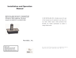
1
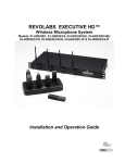
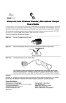
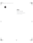
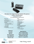
Installation and Operation
Guide
© 2007 REVOLABS, INC. All rights reserved. No part of this
document may be reproduced in any form or by any means
without express written permission from Revolabs, Inc.
Product specifications are subject to change without notice.
Revolabs Solo™ Single Channel
Wireless Microphone System
Models 02-DSKSYS, 04-DSKSYSEU
Revolabs, Inc.
Revolabs Solo™ Single Channel
02-DSKMAN-PAP-11
December 2007 (Rev 3.1)
Table of Contents
Safety and General Information.....................................................1
Introduction ....................................................................................4
System Components .....................................................................5
Revolabs Solo™ Single Channel Charger Base ...........................5
Mute Button ...............................................................................6
Power Module ...........................................................................6
USB Connection ........................................................................6
External Audio Connection........................................................6
Installing the Solo Single Channel System....................................6
Computer Software Set-up........................................................7
Revolabs Solo™ Wireless Microphones .....................................12
Using with Wearable Wireless Microphone.............................12
Using with TableTop Microphone............................................14
Using with XLR Microphone Wireless Adapter .......................15
Using with a Solo Executive Multi-channel System ................18
Charging the Batteries.............................................................18
When to Charge ......................................................................18
Setting the Broadcast Power Level .........................................19
Pairing the Microphone to the Charger Base ..........................20
LED Status Indications ................................................................22
Warranty ......................................................................................23
Solo Single Channel Specifications .............................................24
Safety and General Information
This section contains important information regarding safe and efficient
system operation, and declarations of required certification / regulation
compliance. Please read this information prior to using your Revolabs
system.
FCC User Information and Notice
FCC Registration Number: 0014898290
FCC ID Number: T5V02DSKSYS Revolabs Charger
FCC ID Number: T5V01EXEMIC Revolabs Microphone
Users are not permitted to make changes or modify the equipment in any
way. Changes or modifications not expressly approved by Revolabs, Inc.
could void the user’s authority to operate the equipment.
This device complies with Part 15 of the FCC Rules. Operation is subject
to the following two conditions: (1) this device may not cause harmful
interference, and (2) this device must accept any interference received,
including interference that may cause undesired operation.
Federal Communications Commission (FCC)
Radiation Exposure Statement
Important: This equipment complies with FCC radiation exposure limits
set forth for an uncontrolled environment.
Industry Canada Notice to Users
Operation is subject to the following two conditions: (1) This device may
not cause interference and (2) This device must accept any interference,
including interference that may cause undesired operation of the device
Ref IC: RSS 210 Sec. 5.11. The term “IC:” before the certification /
registration number signifies that registration was performed based on a
Declaration of Conformity indicating that Industry Canada technical
specifications were met. It does not imply Industry Canada approval of
the equipment. See Ref IC Self-Marking 6(f) and RSP-100 Sec. 4.
IC ID Number: 6455A-02DSKSYS Revolabs Solo™ Desktop Charger
IC ID Number: 6455A-01EXEMIC Revolabs Solo™ Microphone
Restricted use with certain medical devices
Hearing Aids
Some devices may interfere with some hearing aids. In the event of such
interference, you may want to consult with your hearing aid manufacturer
to discuss alternatives.
1
Other Medical Devices
WEEE Notification:
If you use any other personal medical device, consult the manufacturer of
your device to determine if it is adequately shielded from RF energy.
Your physician may be able to assist you in obtaining this information.
The Waste Electrical and Electronic Equipment (WEEE) directive
(2002/96/EC) is intended to promote recycling of electrical and
electronic equipment and their components at end of life.
Export Law Assurances
This product is controlled under the export regulations of the United
States of America and Canada. The Governments of the United States of
America and Canada may restrict the exportation or re-exportation of this
product to certain destinations.
For further information contact the U.S. Department of Commerce or the
Canadian Department of Foreign Affairs and International Trade. The use
of wireless devices and their accessories may be prohibited or restricted
in certain areas. Obey the laws and regulations on the use of these
products.
2003/11/EC & 2002/95/EC “RoHS Compliance Directive”:
The products referenced herein are in compliance with the EU
directive 2003/11/EC and EU directive 2002/95/EC.
02-DSKSYS North America UPCS Usage
Restriction
Due to the UPCS frequencies used, this product is licensed for operation
only in the United States of America and Canada.
04-DSKSYSEU European Union Usage Restriction
Due to the frequencies used, this product is licensed for operation only in
the European Union countries.
European Compliance
This equipment has been approved in accordance with Council Directive
1999/5/EC “Radio Equipment and telecommunications Equipment.”
Conformity of the Equipment with the guidelines below is attested by the
CE mark.
Model Numbers:
04-DSKSYSEU-BLK-11 Revolabs Charger
03-EXEMICEU-BLK-11 Revolabs Executive Microphone
05-TBLMICEU-OM-BLK-11 Revolabs Solo™ Table Microphone Omni
05-TBLMICEU-DR-BLK-11 Revolabs Solo™ Table Microphone Cardioid
Standards to which Conformity is declared:
RF
EMC
ETSI EN 301 406 V 1.4.1 03/2001
ETSI EN 301 489-6 v1.2.1 (2002-04)
2
3
System Components
Introduction
Congratulations on the purchase of your Revolabs
Solo™ Single Channel wireless microphone system!
This wireless system provides high band-width audio
from a compact wireless microphone enabling
reliable, secure, and untethered personal
communication.
The Single Channel Wireless Microphone System is a
unique marriage of innovative technology and
ergonomic stylish design, featuring 1.9 GHz DECT
technology. This product enhances audio
communication in both personal and enterprise
applications, using Multi-Carrier, Time Division
Multiple Access and Time Division Duplex
(MC/TDMA/TDD) radio transmissions both to and
from the microphone.
This means that the system can co-exist with other
wireless products such as wireless LANs (802.11 b&g)
and cellular phones.
Your Revolabs Solo™ Single Channel System package
contains:
•
•
Compact Charger Base
Solo Wireless Microphone (varies)
•
•
Power Module
External Audio Cable
•
USB cable
•
•
Installation and Operation Guide
Solo Single Channel Quick Start Guide
Revolabs Solo™ Single Channel Charger Base
Use the Charger Base to store and charge the
Microphone when not in use. The Microphone must
be properly inserted into the base and seated flush for
charging to occur.
Note: It is recommended that no more than 3 Single
Channel Systems, nor a Single Channel and
Multichannel System, be used in the same room to
avoid interference.
1.
2.
3.
4.
Charger Bay — charges Microphone
LED indicator — mute and pairing status indicator
MUTE button — duplicates the Microphone mute function
AUDIO port — 2.5mm analog in/out external audio
connection
5. Mini USB connector — computer audio connection
6. POWER connector — power supply input
4
5
Mute Button
Pressing the MUTE button toggles between muting
(flashing RED LED status) and un-muting (flashing
GREEN LED status) on the Wireless Microphone.
Note: Press the MUTE button on a Microphone will
similarly toggle between mute and un-mute and
display on both status LEDs.
Power Module
The Charger Base requires 5VDC power. Plug the
supplied AC adapter into a convenient 110-240VAC,
50-60Hz power outlet and the adapter into the power
connector.
USB Connection
Use the supplied cable to connect the mini USB
connector to the Charger Base and the standard end
to your computer USB port.
External Audio Connection
The Single Channel System includes a cable for
connecting the Charger Base to an external audio or
conferencing system. The provided 2.5mm miniplugto-RCA cable allows the microphone’s unbalanced
line level audio to be used with a mixer or
conferencing system using the RCA male jack. Output
from the mixer or conferencing system can be
connected to the RCA female plug providing audio to
the microphone’s earpiece. An optional Line-to-mic
level cable (07-STEMIC-PPP) is available for purchase.
Installing
Installing the Solo Single Channel
Channel System
The Revolabs Solo™ Single Channel system is easily
installed into either the office or conference room
environment. Simply plug the power supply into a
convenient outlet and attach the USB cable to a
computer or laptop, or connect the 2.5mm audio
cables to an audio system. Power is not provided by
the USB cable.
6
Computer Software Set-up
Use the supplied USB cable to connect the mini USB
connector to the Charger Base and the standard end
to your computer USB port. Your computer will alert
you that it has found a new USB device.
It is possible to configure your computer settings to
playback audio through the earpiece attached to the
Wearable microphone (default settings) or through the
computer speakers (internal or desktop).
The following examples use the Microsoft Windows®
XP Operating System Classic settings. You may notice
slight differences in appearance when using other
Windows operating systems.
To modify the default microphone earpiece audio
output settings:
1. At the lower-right of your screen, click the Start
button.
2. Select Settings and Control Panel.
3. Click the Sounds and Audio Devices icon.
7
4. Open the Volume settings for Sound recording
to view the volume levels selected for the
microphone input (Capture) on the computer.
The Sounds and Audio Devices Properties dialog will
display, as shown. The solo-Desktop device will be
selected.
5. Make sure that the level for the Microphone is
close to the top (maximum) and that the Mute
box is not checked.
6. In the Sound playback section, open the
Volume settings for to control the volume you
hear in the Microphone’s earpiece.
Adjust the Speaker level at the master Volume
control if necessary.
8
9
7. At the bottom of the Microphone section, click
the Mute box in the Microphone section to
prevent the Microphone directly feeding back
its own audio to the earpiece (i.e. “sidetone”).
It may be necessary to use the OptionsProperties menu to display the Microphone
volume control.
IP telephony and computer telephony
applications (e.g., Skype) may also offer options
for controlling the audio levels and playback
capabilities. Please consult the application
guide for the software package for additional
instructions.
8. Change the Sound playback Default device to
your regular audio codec (SigmaTelAudio in
this example) to playback audio through the
internal or external speakers of the computer
instead of the earpiece.
9. At the bottom of the dialog, click Apply, and
then click OK.
Note: Laptop computers with built-in microphones
may continue to operate even when the solo-Desktop
software is running. To prevent the built-in microphone
audio feeding through to the speakers, check the Mute
box on the laptop audio program Input Monitor, as
shown below.
10
11
Revolabs Solo™ Wireless Microphones
Microphones
Using with Wearable Wireless Microphone
The wireless personal microphone uses encrypted
communication to synchronize with the Charger
Base. It provides high quality full duplex audio
between the user and the computer, audio or video
conference system or external audio system. The
system allows the wearer to step out of the office or
conference room and still participate in the call.
1. Microphone port — direct toward mouth for best audio pickup.
2. Noise cancelling port — do not block opening.
3. Mute Button — press to mute, un-mute and pair microphone.
4. Pocket clip — also used to attach microphone to lanyard.
5. LED display — visual status for mute, un-mute, and pairing.
6. Earpiece jack — accepts the 2.5mm plug for the earpiece.
7. Charging port — docks to Solo Charger Bases.
Note: Microphones in new systems must be paired
to the Charger Base. See microphone pairing
instructions on page18.
Revolabs Solo™ Wearable Microphones turn on and
mute automatically when removed from Charger
Base, to reduce noise while being attached. The
microphone has a clip on the back which allows the
microphone to be easily attached onto a shirt pocket,
blouse, lapel or lanyard.
To use the Wearable Microphone:
12
1. Remove the microphone from the Charger Base.
The double-flashing RED LED on the Microphone
and Charger Base confirm that the mic is paired
and muted.
2. Attach the microphone to clothing or to a lanyard
close to the mouth, within 6-12 inches (15–30cm)
is recommended. Make sure microphone is
attached securely with the microphone port
pointed up toward mouth.
3. With the microphone in the wearing position, unmute the microphone by pressing and releasing
the Mute button (confirm by viewing flashing
GREEN LED). If the volume is too low, move the
microphone closer to the mouth.
4. To turn microphone off, return the Microphone to
the Charger Base. The Microphone LED will show
a 5 second self-test pattern and begin charging
(solid RED or GREEN LED). Alternately, turn off
the Microphone manually by pressing and holding
the Mute button for 10 seconds, until the LED
turns solid RED, then release the mute button and
the LED will turn OFF.
If the microphone is moved out of range of the
Charger Base (~65 feet or 20m) the connection will be
dropped (LED flashes all colors) and the microphone
will mute.
After 15 seconds the microphone will beep 5 times,
and will continue beeping every 30 seconds to remind
the user to return the microphone to the conference
room. If the microphone is moved back into range
within 15 minutes the connection will automatically
be re-established to its original state, and the beeping
will cease. If not, the microphone will turn off.
Adjusting the Volume on the Wearable Microphone Earpiece
To change the volume on the Wearable microphone
earpiece, use the dial on the earpiece wire.
13
LED), to reduce noise while placing the
microphone on the table.
Turning the dial towards the earpiece, as shown in
the figure, will increase the volume, and turning
the dial towards the microphone will decrease the
volume. Use the attached clothing clip to secure
the earpiece wire.
Using with TableTop Microphone
The Revolabs Solo™ TableTop Wireless Boundary
Microphones enable multiple phone conference
participants to use a single microphone. Units are
placed strategically on the conference table to ensure
that all participants can be heard clearly.
1.
2.
3.
4.
5.
6.
Mute Button — press to mute, un-mute and pair microphone.
LED display — visual status for mute, un-mute, and pairing.
Integral grille — protects internal parts (non-removable).
Audio jack — accepts a 2.5mm plug for a powered speaker.
Charging port — docks to all Solo Charger Bases.
Rubber feet — non-slip, vibration absorbing pads.
To use the Wireless TableTop Microphone:
1. Remove the microphone from the Charger Base.
The microphone turns on and mutes automatically
when removed from Charger Base (flashing RED
14
2. TableTop microphones should be centered on the
table with the integral grill pointed toward the
users (uni-directional), or centrally located
between users (omni-directional), from 2 to 5 feet
(.75 to 1.75m) away. It is always better to be as
close to the person speaking as possible, but avoid
placing the microphone where it might be blocked
by equipment or meeting paperwork. Also do not
place microphones too close to an audio or video
conference speaker to avoid echoes.
3. With the microphone in position, un-mute the
microphone by pressing and releasing the MUTE
button (confirm by viewing flashing GREEN LED).
4. To turn microphones off, return the microphone
unit to the Charger Base. The Microphone LED
will show a 5 second self-test pattern and begins
charging (solid RED or GREEN LED). Alternately,
press and hold the MUTE button for 10 seconds
until the LED turns solid RED, then release the
mute button and the LED will turn OFF.
If the microphone is moved out of range of the
Charger Base (~65 feet or 20m) the connection will be
dropped (LED flashes all colors) and the microphone
will mute.
After 15 seconds the microphone will beep 5 times,
and will continue beeping every 30 seconds to remind
the user to return the microphone to the conference
room. If the microphone is moved back into range
within 15 minutes the connection will automatically
be re-established to its original state, and the beeping
will cease. If not, the microphone will turn off.
Using with XLR Microphone Wireless Adapter
The Revolabs Solo™ Universal Wireless Adapter for
Handheld Microphones, shown in the following figure,
is connected to your existing handheld dynamic
15
microphones for wireless freedom during open mic
meetings, Q&A sessions, classrooms, etc.
The Adapter does not provide phantom power or
bias current so it cannot be used with condenser
or electret microphones.
7. 1. Mute button — press to mute, un-mute and pair
microphone.
8. 2. Rubber collar — durable and impact/strain protection.
9. 3. XLR Female connector — balanced audio for dynamic
microphones.
10.
4. LED display — visual status for mute, un-mute,
and pairing.
11.
5. Audio Out port — accepts the 2.5mm plug for
the earpiece.
6. Power/Charging Port — docks to all Solo Charger
Bases.
To use the Revolabs Solo™ Universal Wireless
Adapter:
5. Remove the Microphone Adapter from the Charger
Base.
The adapter turns on and mutes automatically
when removed from Charger Base (flashing RED
LED). The XLR Microphone Adapter is attached to
a standard dynamic microphone to convert it from
a wired microphone to a wireless microphone (see
following figure).
16
6. With the microphone attached, un-mute the
Adapter by pressing and releasing the Mute button
(confirm by viewing flashing GREEN LED).
Note: If the microphone has an on-board mute
switch, this switch must also be un-muted prior to
use.
7. To turn the Adapter off, return the microphone
unit to the Charger Base or press and hold the
Mute button for ~10 seconds until the LED turns
solid RED and release button.
Important: Always remove the microphone from
the Adapter by pressing the latch switch and
separating the parts before returning the Adapter
to the Charger Base.
If the microphone is moved out of range of the
Charger Base (~65 feet or 20m) the connection will be
dropped (LED flashes all colors) and the microphone
will mute.
After 15 seconds the microphone will beep 5 times,
and will continue beeping every 30 seconds to remind
the user to return the microphone to the conference
room. If the microphone is moved back into range
within 15 minutes the connection will automatically
17
be re-established to its original state, and the beeping
will cease. If not, the microphone will turn off.
Using with a Solo Executive Multi-channel System
The Revolabs Solo™ Single Channel Wearable
Microphone can be paired to a Solo Executive Multichannel Wireless Microphone System for users who
wish to have a single microphone to use in both the
office and in the conference room. This is
accomplished by pairing the Single Channel Wearable
Microphone to the Executive Multi-channel Base
Station and docking the Microphone in the Executive
Charger Base. The Microphone can then be used in
either system by placing the Microphone in the
respective Charger Base for about 5 seconds.
Charging the Batteries
To charge the batteries place the Microphone into the
Single Channel Charger Base. During charging, the
Microphone status LED indicator changes from solid
RED to solid GREEN as charging completes. The
Charger Base status indicator remains off during
charging. The Microphone is always muted while in
the Charger Base. The battery charges from fully
depleted to fully charged in approximately two hours,
however, it is “quick-charged” to 80% capacity in 45
minutes.
Note: A fully charged battery provides approximately
8 hours of talk time.
When to Charge
Before using the Microphone for the first time, charge
for 8 hours or overnight in the Charger Base (until
microphone LED turns solid GREEN).
When the Microphone LED begins flashing alternating
YELLOW and RED or YELLOW and GREEN, the
battery needs recharging. Over time (years), batteries
gradually wear down and require charging after a
shorter period of use. This is normal.
18
Important: The Lithium Polymer rechargeable battery
that powers the Microphone is not user serviceable.
Please see the Revolabs website (www.revolabs.com) for
information regarding battery replacement and proper
disposal procedures. Warning: Exposing the
batteries to fire may result in an explosion.
Setting the Broadcast Power Level
In confined settings where multiple Solo Executive
Single Channel systems are used, or where audio
interference is likely, it may be necessary to reduce
the broadcast power levels.
The broadcast power level between the Microphone
and Charger Base can be set to the following three
levels.
•
Highest power level – 60 feet (25M) maximum
operating distance between Microphone and
Charger Base (default setting).
•
Medium power level – 20 feet (7M) maximum
operating distance between Microphone and
Charger Base.
•
Lowest power level – 6 feet (2M) maximum
operating distance between Microphone and
Charger Base.
To set the broadcast power level:
Press and hold the Mute button while plugging the
USB cable into the Charger Base.
The status LED on the Charger Base will display a
sequence of flashes, during which it will flash once,
then twice, then three times, where:
1 GREEN flash = full power
2 GREEN flashes = medium power
3 GREEN flashes = low power.
This cycle will repeat 10 times. During any of the
cycles, simply release the Mute button immediately
after the desired power indication, to set the
19
Executive Single Channel system broadcast/receive
power.
alternately GREEN and RED for a few seconds and
turn OFF. If this happens, repeat these steps.
Pairing the Microphone to the Charger Base
“Pairing” creates an encrypted association between
the Wireless Microphone and the Charger Base with a
unique electronic serial number. When the
Microphone and Charger Base have been previously
paired, the Microphone will automatically try to
connect to the Charger Base whenever it is lifted from
the Charger Base.
Note: The Microphone in new systems will need to be
manually “paired” prior to first use.
If a Microphone is lifted from the Charger Base and
the Microphone LED slowly flashes alternating RED
and GREEN for 10 seconds, it means that the
Microphone needs to be paired to the system.
To pair the Microphone to the Charger Base:
1. Make sure the Microphone is turned OFF (no LED
activity). If the unit is ON, press and hold the
MUTE button for 10 seconds until the LED turns
solid RED then release. Alternately, place the
Microphone in the Charger Base for less than 2
seconds.
2. Enable the pairing mode by holding the
Microphone’s Mute button down for eight seconds.
The LED will turn solid GREEN and then solid
RED. Release the Mute button. The Microphone
unit is now in pairing mode.
3. Push and hold the Charger Base’s Mute button for
eight seconds to enter into pairing mode then
release.
4. The LED will be solid RED until pairing is
complete, as indicated by double flashing RED on
both the Microphone and the Charger Base (paired
and muted audio). If pairing fails at the end of one
minute on either unit, the LED will flash
20
21
LED Status Indications
Warranty
The following LED patterns are shown on either the
Microphone or the Charger Base.
Revolabs, Inc. warrants this product to be free of manufacturing
defects. Repair or replacement of any defective part or unit (at the
discretion of the Seller) will be free of charge for the period of 90
days.
LED Pattern
Solid GREEN
(Microphone only*)
Solid RED
GREEN flash every 1.5
seconds
Two RED flashes every
1.5 seconds
YELLOW flash
alternating with GREEN
flash
YELLOW flash
alternating with two RED
flashes
Alternating RED,
YELLOW, GREEN,
YELLOW (Microphone
only)
Alternating slow RED
and GREEN
Rapid RED flashes
continuing for more than
a few seconds
Groups of five rapid red
flashes
Meaning
Confirmation of power-up or battery
reaching full charge. * In earlier versions
LED will turn OFF when fully charged.
Pairing mode, or confirmation of poweringdown, or battery charging.
Microphone paired, connected and unmuted.
Microphone paired, connected and muted.
Microphone paired, connected, un-muted
and battery low.
Microphone paired, connected, muted and
battery low.
Searching for a connection, or out of radio
range. The Microphone will try to reestablish the link for about 15 minutes, and
then turn off automatically. The Microphone
will beep five times every 30 seconds.
Microphone is not paired to Base Station.
Any attempt by the user to alter the equipment, or equipment
damaged by negligence, accident, or Acts of God voids this
warranty.
The Seller shall not be liable for any consequential damage
resulting from the malfunction of this product. Should the user
experience unsatisfactory performance from this equipment,
contact the Seller to obtain instructions for return, or replacement,
as deemed necessary.
This warranty is not transferable by the original end user.
Revolabs, Inc.
63 Great Road
Maynard, MA 01754
www.revolabs.com
1-800-326-1088
Radio congestion – it is not possible to
make a radio connection because there are
already too many nearby users, or there is
heavy radio interference. Interference may
be caused by some types of digital cordless
phones, and other Revolabs Solo™
installations.
Unit is faulty. Please contact your place of
purchase for advice on return.
22
23
Solo Single Channel Specifications
Dimensions, (L, W, H) and Weight
Single Channel Charger Base
3.9” (10 cm) x 2.4” (6 cm) x 1.0” (2.56 cm), 0.5 lb (0.23 kg)
Wearable Microphone:
0.9” (2.3 cm) x 0.8” (2.0 cm) x 2.6” (6.6 cm), 0.05 lb (0.02 kg)
TableTop Microphone:
1.5” (3.8 cm) x 0.8” (2.0 cm) x 3.3” (8.4 cm), 0.05 lb (0.02 kg)
XLR Adapter:
0.9” (2.3 cm) x 0.8” (2.0 cm) x 4.0” (10.2 cm), 0.05 lb (0.02 kg)
Shipping Weight
1.5 lbs (0.68 kg)
Radio Frequency
02-DSKSYS - 1.92 to 1.93 GHz (UPCS North America)
04-DSKSYSEU - 1.88 to 1.90 GHz (DECT EU)
Connectors
Single Channel Charger Base
Power – 5VDC, proprietary 0.7mm connector
Mini USB – 5 pin connector, USB 2.0
Audio unbalanced In/Out – 2.5mm
Tip: Audio Out (line level, 0dBV)
Ring: Audio In (line level, 0dBV)
Shield: GND
Wireless Microphone
Power – proprietary 4 pin connector
Audio – 2.5mm mono audio
Microphone patterns Executive unidirectional – cardioid.
TableTop omni-directional and uni-directional available.
Power Requirements
Power Adapter
110 - 240VAC, 50-60Hz to 5VDC, 300mA
Battery
Lithium Polymer, up to 8 hours talk time
Charge Time
2.0 hours approx.
Range
65’ (20 meters) approx. (no obstructions)
Audio Bandwidth
100-7000 Hz
Encryption
128-bit DSAA (DECT Standard
Authentication Algorithm) authentication,
64 bit DECT Standard Cipher
Environmental Requirements
Temperature
40° to 105° F (5° to 40° C) operating
Humidity
20% to 85%
24
Note: Microphones must be fully charged
and paired to the Charger Base
prior to first use.
Revolabs Solo™ Single Channel
02-DSKMAN-PAP-11
December 2007 (Rev 3.1)
25