1
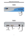
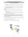
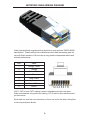
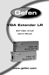
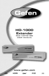
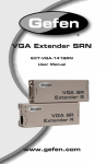
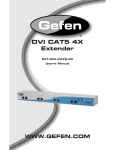
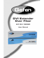
®®
DVI Extender
Over Fiber
EXT-DVI-1500HD
User Manual
ASKING FOR ASSISTANCE
Technical Support:
Telephone
Fax
(818) 772-9100
(800) 545-6900
(818) 772-9120
Technical Support Hours:
8:00 AM to 5:00 PM Monday through Friday PST
Write To:
Gefen, LLC
c/o Customer Service
20600 Nordhoff Street
Chatsworth, CA 91311
www.gefen.com
[email protected]
Notice
Gefen, LLC reserves the right to make changes in the hardware, packaging,
and any accompanying documentation without prior written notice.
DVI 1500 Extender is a trademark of Gefen, LLC
© 2011 Gefen, LLC. All rights reserved.
All trademarks are the property of their respective owners.
Rev X6
TABLE OF CONTENTS
1.
Introduction / Operation Notes
2.
Features
3.
Sender Panel Descriptions
4.
Receiver Panel Descriptions
5.
Connecting and Operating the DVI 1500
6.
Network Cable Wiring Diagram
7.
Specifications
8.
Warranty
INTRODUCTION
The Gefen DVI•1500 allows a single link video signal to be extended over long
distances by using a multimode with LC termination. Fiber Optics technology
allows the DVI•1500 to carry video signals over long distances that would not be
possible with traditional CAT5 extension. The use of fiber optic cabling protects
the video signal from electromagnetic interference (EMI) which can degrade the
video signal.
How It Works
The DVI•1500S sender unit sits next to your computer, set-top box or DVD player
source. Cables supplied with the DVI•1500 connect your DVI source to the send
unit. The DVI•1500R receive unit sits next to your DVI display - up to 1640 feet
(330 feet with HDCP) away. The display plugs into the back of the DVI•1500R
receiver unit. One CAT-5 cable and a multimode LC-LC fiber optic cable (4
strand) connect the DVI•1500S and the DVI•1500R units to each other.
OPERATION NOTES
READ THESE NOTES BEFORE INSTALLING OR
OPERATING THE DVI 1500
•
50 or 62.5 micron multimode fiber optic cable is required for operation of the
DVI 1500.
•
Maximum extension range of 330 feet (100 meters) when the source
requires HDCP. One CAT-5, CAT-5e or CAT6 cable is used to transmit DDC
and HDCP data back to the source.
•
Maximum range of 1640 feet (500 meters) when the source does not require
HDCP. This scenario does not require the CAT-5, CAT5e or CAT-6 cable if
the source does not require DDC information. If DDC is required, the use of
an EDID storage device (part# EXT-DVI-EDIDN, EXT-DVI-EDIDP) can be
used to transmit DDC information back to the source.
•
HDCP compliant
•
Compatible with all DVI and HDMI* displays.
NOTE: *When used with a HDMI to DVI adapter
1
FEATURES
Features
•
Extends any DVI (digital visual interface) compliant device up to 1640 feet/500 meters
(330 feet with HDCP) from the computer
•
Uses a four-strand multimode LC-LC fiber optic cable for video signals
•
Uses one CAT-5 cable for DDC and control signals
•
Eliminates computer noise where you work
•
Supports resolutions up to 1080p, 2K, and 1920 x 1200
•
Supports DDWG standard for DVI compliant monitors
•
HDCP compliant
Includes:
(1) DVI 1500S Sender unit
(1) DVI 1500R Receiver unit
(2) 5V DC Power Supply
(1) 6 ft DVI cable (M-M)
(1) User’s Manual
2
SENDER PANEL DESCRIPTIONS
Front Panel
Power LED
Indicator
Status LED
Indicator
Back Panel
Fiber Optic
LC-LC Terminals
DVI Input
Port
RJ-45
Port
5V DC
Power Input
3
RECEIVER PANEL DESCRIPTIONS
Front Panel
Power LED
Indicator
Status LED
Indicator
Back Panel
RJ-45
Port
DVI Output
Port
5V DC
Power Input
4
Fiber Optic
LC-LC Terminals
CONNECTING AND OPERATING THE DVI 1500
How To Connect The DVI 1500
1.
Connect the DVI source device to the DVI 1500 sender unit using the supplied
DVI cable.
2.
Connect a user supplied CAT-5, CAT-5e or CAT-6 cable to the sender unit.
3.
Connect four user supplied multi-mode LC-LC terminated fiber optic cables
into the DVI 1500 sender unit.
NOTE: 50 or 62.5 micron multi-mode fiber optic cable is required for correct
operation.
4.
Connect the other end of the CAT-5, CAT-5e or CAT-6 cable into the DVI
1500 receiver unit.
5.
Connect the other ends of all four multi-mode LC-LC terminated fiber optic
cables into the DVI 1500 receiver unit.
NOTE: Please take careful note of the labeling above each fiber optic port on
both the sending and receiving DVI 1500 units. The most common user error is
to mis-match the fiber optic cable connections on each end, which results in no
video being transmitted.\
6.
Connect the included 5V DC power supplies into both sender and receiver.
7.
Power on the display, then the source.
No further adjustments are necessary to operate the DVI 1500.
4X FIBER OPTIC LC-LC CABLE
(Up To 1,640 FT)
CAT-5
CABLE
(Up To 1,640 FT, 330 FT w/HDCP)
DVI CABLE
Computer
Receiver
DVI Monitor
Sender
EXT-DVI-1500HD
5
NETWORK CABLE WIRING DIAGRAM
Gefen has specifically engineered their products to work with the TIA/EIA-568-B
specification. Please adhere to the table below when field terminating cable for
use with Gefen products. Failure to do so may produce unexpected results and
reduced performance.
Pin
Color
1
Orange / White
2
Orange
3
Green / White
4
Blue
5
Blue / White
6
Green
7
Brown / White
8
Brown
12345678
CAT-5, CAT-5e, and CAT-6 cabling comes in stranded and solid core types.
Gefen recommends using solid core cabling. CAT-6 cable is also recommended
for best results.
Each cable run must be one continuous run from one end to the other. No splices
or use of punch down blocks.
6
SPECIFICATIONS
Video Amplifier Bandwidth ....................................................... 225 MHz maximum
Input Video Signal .............................................................................. 1.2 Volts p-p
Input DDC Signal ......................................................................... 5 Volts p-p (TTL)
Single Link Range ............................................................ 1080p, 2k, 1920 x 1200
DVI Connector ..................................................................... DVI-D (19 pin) female
Video Link Connector ........................................................................................ LC
DDC Link Connector ...................................................................... RJ-45 Shielded
Power Supply .......................................................... 5V DC with locking connector
Power Consumption .............................................................. 36W watts x 2 (max)
Link Connectors ............................................................. LC Fiber, Shielded RJ-45
Rack mountable .............................................................................. 1U rack space
Dimensions ......................................................................... 3.25”D x 4.25”W x 1”H
Shipping Weight ............................................................................................ 5 lbs.
Rack mountable .............................................................................. 1U rack space
7
8
WARRANTY
Gefen warrants the equipment it manufactures to be free from defects in material
and workmanship.
If equipment fails because of such defects and Gefen is notified within two (2)
years from the date of shipment, Gefen will, at its option, repair or replace the
equipment, provided that the equipment has not been subjected to mechanical,
electrical, or other abuse or modifications. Equipment that fails under conditions
other than those covered will be repaired at the current price of parts and labor in
effect at the time of repair. Such repairs are warranted for ninety (90) days from
the day of reshipment to the Buyer.
This warranty is in lieu of all other warranties expressed or implied, including
without limitation, any implied warranty or merchantability or fitness for any
particular purpose, all of which are expressly disclaimed.
1.
Proof of sale may be required in order to claim warranty.
2.
Customers outside the US are responsible for shipping charges to and from
Gefen.
3.
Copper cables are limited to a 30 day warranty and cables must be in their
original condition.
The information in this manual has been carefully checked and is believed to
be accurate. However, Gefen assumes no responsibility for any inaccuracies
that may be contained in this manual. In no event will Gefen be liable for
direct, indirect, special, incidental, or consequential damages resulting from
any defect or omission in this manual, even if advised of the possibility of such
damages. The technical information contained herein regarding the features and
specifications is subject to change without notice.
For the latest warranty coverage information, refer to the Warranty and Return
Policy under the Support section of the Gefen Web site at www.gefen.com.
PRODUCT REGISTRATION
Please register your product online by visiting the Register Product page
under the Support section of the Gefen Web site.
Rev X6
Pb
This product uses UL listed power supplies.