Download Scosche GM1504W mounting kit
Transcript
IN-DASH INSTALLATION KIT FOR GM1504/ GM1504W 1982-2005 GENERAL MOTORS VEHICLES CHEVROLET (Cont'd) BUICK 1982-96 1985-90 1992-94 1986-91 1991-94 1984-87 1995-99 1991-94 1982-89 1992-95 1983-85 CENTURY .................... 7 ELECTRA/PARK AVENUE....................... 7 LE SABRE .................... 8 LE SABRE .................... 7 PARK AVENUE ............ 8 REGAL ......................... 7 RIVIERA ....................... 8 ROADMASTER ............ 8 SKYHAWK ................... 9 SKYLARK..................... 9 SKYLARK..................... 9 CADILLAC 1982-88 1992-95 1985-91 1986-91 1984-85 2002 1999-02 1985-92 1986-91 1984-85 CIMARRON................ 10 DEVILLE ..................... 10 DEVILLE ..................... 10 ELDORADO ............... 11 ELDORADO ............... 11 ESCALADE EXT ......... 11 ESCALADE ................ 11 FLEETWOOD ............. 10 SEVILLE ..................... 11 SEVILLE ..................... 11 CHEVROLET 1996-02 1990-95 1985-89 2001-02 1991-96 1989-91 1997-02 1993-96 1982-92 1994-96 1991-93 ASTRO ....................... 12 ASTRO ....................... 12 ASTRO ....................... 12 AVALANCHE.............. 11 BERETTA ................... 12 BLAZER, FULL SIZE .. 13 CAMARO ................... 13 CAMARO ................... 13 CAMARO ................... 14 CAPRICE CLASSIC ... 14 CAPRICE/CAPRICE CLASSIC...................... 8 19851/2-90 CAVALIER RS, Z-24 .. 15 1982-90 CAVALIER ("VL" OR BASE MODELS)......... 10 1995-99 CAVALIER .................. 15 1991-94 CAVALIER .................. 15 1982-90 CELEBRITY................ 16 1985 CITATION................... 16 1991-96 CORSICA ................... 12 1984-89 CORVETTE ................ 16 1995-02 CREW CAB DUALLY PICKUP...................... 11 1989-91 1986-87 1996-00 1994-96 1995-99 1990-94 1994-96 1990-93 1997-00 1995-99 1986-88 1985-88 1995-02 1995-02 1989-91 1998-01 1986-94 1982-85 1998-01 1986-93 1982-85 1995-02 1988-95 1997-99 CREW CAB DUALLY PICKUP...................... 15 EL CAMINO ............... 19 EXPRESS ................... 17 IMPALA SS ................ 14 LUMINA ..................... 17 LUMINA ..................... 17 LUMINA APV ............. 18 LUMINA APV ............. 18 MALIBU ..................... 18 MONTE CARLO ......... 17 MONTE CARLO ......... 19 NOVA ......................... 19 PICKUP, FULL SIZE .. 11 SUBURBAN ............... 11 SUBURBAN ............... 13 S-10 BLAZER ............ 19 S-10 BLAZER ............ 20 S-10 BLAZER ............ 20 S-10 PICKUP ............. 19 S-10 PICKUP ............. 20 S-10 PICKUP ............. 20 TAHOE ....................... 11 VAN, FULL SIZE ........ 20 VENTURE .................. 21 1989-91 1989-91 1995-02 1998-01 1986-94 1982-85 1986-93 1982-85 1996-03 1990-95 1985-89 1996-00 1998-01 1995-99 1989-91 1988-95 2002 1995-02 1998-00 HOMBRE PICKUP ..... 19 OLDSMOBILE 1992-95 1991-94 1985-91 1982-96 1989-94 1984-88 1986-88 1992-93 1989-91 1982-88 1984-93 1983-84 1997-99 1994-96 1990-93 1982-89 1989-93 ACHIEVA.................... 21 BRAVADA .................. 20 CUTLASS CALAIS ..... 21 CUTLASS CIERA ....... 22 CUTLASS SUPREME 22 CUTLASS SUPREME CLASSIC.................... 22 DELTA 88................... 23 EIGHTY-EIGHT ROYALE ..................... 23 EIGHTY-EIGHT ROYALE ..................... 23 FIRENZA .................... 11 NINETY-EIGHT .......... 23 OMEGA...................... 23 SILHOUETTE ............. 21 SILHOUETTE ............. 18 SILHOUETTE ............. 18 TORONADO............... 24 TOURING SEDAN...... 24 PONTIAC GMC 1995-02 ISUZU CREW CAB DUALLY PICKUP...................... 11 CREW CAB DUALLY PICKUP...................... 13 JIMMY, FULL SIZE .... 13 PICKUP, FULL SIZE .. 11 S-15 JIMMY............... 19 S-15 JIMMY............... 20 S-15 JIMMY............... 20 S-15 PICKUP ............. 20 S-15 PICKUP ............. 20 SAFARI ...................... 12 SAFARI ...................... 12 SAFARI ...................... 12 SAVANA..................... 17 SONOMA PICKUP ..... 19 SUBURBAN ............... 11 SUBURBAN ............... 13 VAN, FULL SIZE ........ 20 YUKON XL ................. 11 YUKON ..................... 11 1992-99 1987-91 1984-88 1993-02 1985-92 1982-84 1996-98 1992-95 1985-91 1997-99 1994-96 1992-93 1982-88 1995-99 1997-99 1994-96 1990-93 1982-91 BONNEVILLE ............. 24 BONNEVILLE ............. 25 FIERO ........................ 25 FIREBIRD ................... 25 FIREBIRD ................... 26 FIREBIRD ................... 14 GRAND AM................ 26 GRAND AM................ 26 GRAND AM................ 26 GRAND PRIX ............. 27 GRAND PRIX ............. 27 GRAND PRIX ............. 27 SUNBIRD/J-2000 ...... 10 SUNFIRE/ CONVERTIBLE .......... 28 TRANS SPORT .......... 21 TRANS SPORT .......... 18 TRANS SPORT .......... 18 6000 ........................... 28 SATURN 1991-94 SC, SL, SL1, SL2 ....... 28 CAR STEREO CONNECTORS PROVIDE EASY CONNECTION OF YOUR CAR STEREO TO FACTORY WIRING HARNESS. GM01 GMDA 1978-87 General Motors Vehicles 1988-up General Motors Vehicles LIABILITY DISCLAIMER This instruction booklet is based on carefully documented data and research of automobile dash disassembly, wire harness/codes and information pertaining to installation of this kit (GM1504) in 1982-2002 General Motors Vehicles. Scosche Industries, Inc. cannot be held responsible for discrepancies/inconsistencies that may occur due to the automobile manufacturing changes or options, or damage that may occur in the automobile during the installation of components while using this booklet. If you have any further questions, call our toll free technical help line at: 1-800-621-3695x3 © 2008 SCOSCHE INDUSTRIES, INC. SI 8/08 - GM1504/GM1504W (3000499) QUICK START GUIDE INTRODUCTION The Scosche In-Dash Installation Kit for 1982-2002 General Motors Vehicles provides the parts you need to mount your aftermarket car stereo/CD player into your vehicle’s dash. Refer to the individual instructions in this manual to remove your vehicle’s factory installed radio. PRELIMINARY BEFORE BEGINNING Read QUICK START GUIDE PAGES 2-4 CAUTION: DISCONNECT YOUR VEHICLE’S NEGATIVE BATTERY TERMINAL BEFORE THE INSTALLATION TO HELP PREVENT ELECTRICAL DAMAGE. WE RECOMMEND THE USE OF A VOLT/OHM METER OVER A TEST LIGHT TO CHECK WIRING. A TEST LIGHT OR GROUNDED WIRE PROBE CAN CAUSE DAMAGE TO THE VEHICLE’S COMPUTER AND/OR DIAGNOSTIC SYSTEMS. AVOID ALL FACTORY AIRBAG WIRING - AIRBAGS CAN ACCIDENTALLY DEPLOY CAUSING SERIOUS INJURY OR DEATH. • See your vehicle’s instructions for any special tools your installation might require. • Read all instructions accompanying your car stereo for proper wiring & mounting instructions. SCOSCHE GM UNIVERSAL KITS PARTS LIST: • • • • • • KIT PANEL HARDWARE FACTORY BRACKET ADAPTERS UNIVERSAL BRACKETS INSTRUCTIONS TRUCK, VAN & SUV BRACKETS (#2171) 2 QUICK START GUIDE PICK YOUR VEHICLE Locate your vehicle on the front cover of this instruction and disassemble the dash. FACTORY RADIO? Does your vehicle have the factory radio? If YES, proceed to next If NO, go to REMOVING FACTORY MOUNTING BRACKETS If your original radio is secured to the dash with factory mounting bracket(s), use a 10mm socket wrench to remove the nut and the bracket(s) as shown. NOTE: The factory radio may have brackets on the sides, top and/or bottom. REMOVE FACTORY BRACKETS ASSEMBLY WITH FACTORY BRACKETS TOP/BOTTOM: Use the supplied carriage bolts and nuts to attach the factory mounting brackets directly to the kit panel as shown. NOTE: If your bracket has small notches on it, they will have to be flattened out or filed off in order to mount the bracket to the top/bottom of the kit (see inset). SIDES: Attach the Factory Bracket Adapters FBA to left and right sides of the kit as shown. The FBA’s locator pins should line up with the holes marked #1 on the sides of the kit panel. Be sure to insert a carriage bolt through the FBA facing outward through the square hole (see illustration). Repeat for both sides. NOTE: Top and bottom factory brackets bolt directly to kit. BEND TAB FLUSH LOCATOR PIN FACTORY BRACKET ADAPTOR "FBA" CARRIAGE BOLT FACTORY RADIO MOUNTING BRACKET Go to 3 HEX FLANGE NUT QUICK START GUIDE ASSEMBLY WITH UNIVERSAL BRACKETS ATTACHING THE SUPPLIED UNIVERSAL BRACKETS: (If no factory brackets are available) The supplied mounting panel and brackets have numbered holes, and each bracket is labeled with a letter. Before you attach the brackets to the panel, locate the instructions for your vehicle in this manual. Each vehicle’s instructions shows which brackets and holes to use for assembling the kit. After you identify the proper bracket and holes, mount them as shown in this section. Secure the specified bracket to the kit using the supplied cinch studs and nuts. Insert the cinch stud through the inside of the kit wall as shown. Attach the brackets to the mounting panel using the cinch studs and nuts supplied with the kit as shown. BRACKET HOLE NUMBERS ARE IMPRINTED ON BRACKET CINCH STUD KIT HOLE #6 INSIDE KIT WALL BRACKET B HOLE 3 CINCH STUDS KIT HOLE NUMBERS ARE IMPRINTED ON KIT USE THE SHADED TABS AND CUT OFF THE REMAINING KIT PANEL BREAK OFF THE LIP ON THE EDGE OF THE BRACKET CINCH STUD Go to ASSEMBLY WITH TRUCK/SUV/VAN BRACKETS Attach the Truck/SUV/Van brackets to the GM1504 side walls as shown using the cinch studs and nuts provided. Use two studs for each bracket in lower kit holes #2 and #8. Each bracket contains support pins which rest in kit holes #4 and #7. KIT HOLE #8 CINCH STUD 2171 LEFT BRACKET KIT HOLE #2 2171 RIGHT BRACKET Go to 4 CINCH STUD QUICK START GUIDE STEREO ASSEMBLY NOTE: The mounting sleeve must be removed from the stereo first! Your stereo may be snapped into its sleeve. Slide the mounting sleeve (metal shroud) off the stereo towards the back. REMOVE SLEEVE FROM STEREO 1. Locate the locking mechanism on your DIN stereo sleeve (typically) on the side. 2. Slip mounting sleeve towards rear of stereo and remove. FLAT FACE DIN/DETACHABLE FACEPLATE/PULLOUT (DIN E) STEREOS Slide the mounting sleeve (metal shroud) into the panel’s stereo opening and bend all available mounting tabs outward (see inset). Slide the stereo into the mounting sleeve once it has been fastened to the kit panel until the radio locks into place. NOTE: REAR SUPPORT STRAPS NOT INCLUDED. REAR SUPPORTING THE STEREO ADDS TO THE INSTALLATION’S STRUCTURAL INTEGRITY. REAR SUPPORT STRAPS #1504 MOUNTING PANEL DIN MOUNTING SLEEVE (SUPPLIED WITH STEREO) DIN STEREO BEND TABS OUTWARD RADIO'S SUPPLIED TRIMPLATE SHAFT MOUNT INSTALLATION NOTE: SNAP SHAFT MOUNTING TABS NOT INCLUDED. IF REQUIRED FOR YOUR STEREO INSTALLATION, CALL 800-821-3695 x3 FOR IMMEDIATE SHIPMENT. 5 QUICK START GUIDE STEREO CONNECTION* USE THE APPROPRIATE SCOSCHE WIRING CONNECTOR (*not included) Wire up your new aftermarket stereo to the Scosche wiring connector and install the Scosche kit and new stereo assembly in your vehicle. Follow the dash disassembly for your specific vehicle in reverse order to reassemble your dash. CAR STEREO CONNECTORS PROVIDE EASY CONNECTION OF YOUR CAR STEREO TO FACTORY WIRING HARNESS. GM01 GMDA 1978-87 General Motors Vehicles 1988-up General Motors Vehicles FACTORY WIRING CODES NOTE: All wire codes are viewed as looking at the front of the plug with the wires exiting the rear. 1978-87 GENERAL MOTORS BLACK - POWER 1 = GROUND 2 = POWER 3 = LAMP 4 = POWER ANTENNA WHITE - FRONT SPEAKERS 1 = RF+, RIGHT FRONT POSITIVE 2 = R COMMON, RIGHT COMMON 3 = LF+, LEFT FRONT POSITIVE 4 = L COMMON, LEFT COMMON BLUE - REAR SPEAKERS 1 = LR+, LEFT REAR POSITIVE 2 = L COMMON, LEFT COMMON 3 = RR+, RIGHT REAR POSITIVE 4 = R COMMON, RIGHT COMMON 1988-UP GENERAL MOTORS (Vehicles equipped with "mini-type" connectors) BLACK - POWER 1 = GROUND 2 = DIMMER 3 = ILLUMINATION 4 = POWER ANTENNA 5 = +12V SWITCHED, IGNITION 6 = +12V CONSTANT, BATTERY WHITE - FRONT SPEAKERS 1 = LF-, LEFT FRONT NEGATIVE 2 = LF+, LEFT FRONT POSITIVE 3 = RF-, RIGHT FRONT NEGATIVE 4 = RF+, RIGHT FRONT POSITIVE BLUE - REAR SPEAKERS 1 = LR+, LEFT REAR POSITIVE 2 = LR-, LEFT REAR NEGATIVE 3 = RR+, RIGHT REAR POSITIVE 4 = RR-, RIGHT REAR NEGATIVE 6 1982-1996 Buick Century Read pages 3-6 for kit assembly. RADIO REMOVAL: 1. Remove the four screws from under the top edge of the instrument cluster trim piece. 2. Remove the three screws and the two 7mm hex screws from below the instrument cluster trim piece. 3. Remove the three screws and the rocker-switch trim to the right of the instrument cluster. Pull firmly to remove the rocker-switch trim. "A1" BRACKET USE NOTE: For cars equipped with a LEFT SIDE HOLE #1 RIGHT SIDE "B1" BRACKET column mounted shift lever, position "A1" SOPORTE USA LADO IZQUIERDA LADO DERECHO USE HOLE #2 "B1" the lever in low gear for additional ABERTURA NO. 1 SOPORTE clearance. USA ABERTURA 4. Remove the instrument cluster TRIM NO. 2 trim piece. BRACKET CORTA EL 5. Remove the four screws from SOPORTE the radio brackets, pull the radio out of the cavity, then disconnect the antenna, speaker leads "B2" BRACKET "A2" BRACKET USE USE HOLE #2 FRONT OF KIT and all the electrical connections. HOLE #1 "B2" SOPORTE "A2" SOPORTE USA FRENTE DE ESTUCHE Remove the radio. USA ABERTURA NO. 4 ABERTURA NO. 1 USE THE SHADED BRACKETS & THE INDICATED HOLE LOCATIONS. CUT OFF THE REMAINING BRACKETS & DISCARD. Usa los soportes asombrados y las localizaciónes de aberturas indicadas. Corta los soportes que sobran y desechalas. 1985-90 Buick Electra/Park Avenue 1986-91 Buick Le Sabre Read pages 3-6 for kit assembly. RADIO REMOVAL: 1. Carefully snap off the trim from around the air-conditioning controls. 2. Remove the four screws from behind the trim piece. 3. Slide the radio trim panel to the "A1" BRACKET USE LEFT SIDE left (driver’s side) of the car and HOLE #1 "A1" SOPORTE USA LADO IZQUIERDA remove it. ABERTURA NO. 1 4. Remove the four screws which secure the radio to the dashboard, TRIM BRACKET slide the radio out of the cavity CORTA EL and disconnect the antenna, SOPORTE speaker leads and all the electrical supply harnesses. Remove the radio. "D2" BRACKET USE HOLE #1 "D2" SOPORTE USA ABERTURA NO. 1 RIGHT SIDE LADO DERECHO FRONT OF KIT FRENTE DE ESTUCHE "B1" BRACKET USE HOLE #2 "B1" SOPORTE USA ABERTURA NO. 2 "B2" BRACKET USE HOLE #2 "B2" SOPORTE USA ABERTURA NO. 4 USE THE SHADED BRACKETS & THE INDICATED HOLE LOCATIONS. CUT OFF THE REMAINING BRACKETS & DISCARD. Usa los soportes asombrados y las localizaciónes de aberturas indicadas. Corta los soportes que sobran y desechalas. 1984-87 Buick Regal Read pages 3-6 for kit assembly. RADIO REMOVAL: 1. Remove the radio trim panel by carefully prying outward evenly around the edges. 2. Remove the four screws securing the radio mounting bracket to the dash. Pull the assembly out of the cavity to gain access to the wiring. 3. Disconnect the antenna and all the electrical connections, then remove the radio. "A1" BRACKET USE HOLE #3 "A1" SOPORTE USA ABERTURA NO. 3 "C2" BRACKET USE HOLE #3 "C2" SOPORTE USA ABERTURA NO. 3 RIGHT SIDE LADO DERECHO LEFT SIDE LADO IZQUIERDA FRONT OF KIT FRENTE DE ESTUCHE "A1" BRACKET USE HOLE #3 "A1" SOPORTE USA ABERTURA NO. 3 "B2" BRACKET USE HOLE #3 "B2" SOPORTE USA ABERTURA NO. 3 USE THE SHADED BRACKETS & THE INDICATED HOLE LOCATIONS. CUT OFF THE REMAINING BRACKETS & DISCARD. Usa los soportes asombrados y las localizaciónes de aberturas indicadas. Corta los soportes que sobran y desechalas. 7 1992-94 Buick Le Sabre 1991-94 Buick Park Avenue Read pages 3-6 for kit assembly. RADIO REMOVAL: 1. Extract the two screws from the top underside of the instrument trim bezel. 2. Remove the trim below the dash bezel on the left and right "A1" BRACKET USE HOLE #2 sides of the steering wheel by carefully prying outward with "A1" SOPORTE USA ABERTURA NO. 2 "B1" BRACKET USE a panel removal tool/screwdriver to release the fastening clips. HOLE #2 3. Remove the eight screws located behind the trim securing "B1" SOPORTE USA the dash trim bezel and the lower section of the glove box. ABERTURA NO. 2 4. Remove all four dash vents by pulling them outward and BOTTOM removing the single screw FONDO TOP in each. TOPE 5. Open the glove box and extract the screws from each top corner and remove the glove box. "D1" BRACKET USE 6. Remove the dash trim bezel. HOLE #3 7. Extract the five screws securing "D1" SOPORTE USA the radio, pull the unit out of the ABERTURA NO. 3 FRONT OF KIT dash cavity, unplug all the connectors FRENTE DE ESTUCHE and remove the radio. USE THE SHADED BRACKETS & THE INDICATED HOLE LOCATIONS. CUT OFF THE REMAINING BRACKETS & DISCARD. Usa los soportes asombrados y las localizaciónes de aberturas indicadas. Corta los soportes que sobran y desechalas. 1995-99 Buick Riviera Read pages 3-6 for kit assembly. 1. Gently pull outward on left and right windshield pillar panels to release (2) snap clips and extract each one. 2. Unsnap side dash panels and remove (1) 7mm screw from behind each. FLANGE NUT 3. Extract (6) plastic push-pin fasteners from TUERCO REBORDE under front edge of upper dash pad. TOP Pull outward to remove the bottom TOPE panel of the upper dash pad. 4. Extract (5) 7mm screws securing upper dash pad, lift up and outward to remove pad. 5. Carefully pull outward on dash/instrument bezel to release clips, unplug and remove bezel. BOTTOM FONDO CARRIAGE BOLT 6. Extract (3) 7mm screws from climate PERNO DE PORTE control module, unplug and remove module. 7. Extract (4) 7mm screws securing radio, unplug connectors, antenna lead, and remove radio. RADIO REMOVAL: USE THE SUPPLIED CARRIAGE BOLTS & NUTS TO MOUNT THE FACTORY BRACKET TO THE KIT. Usa los pernos de porte y tuercos proveidos para ensamblar la abrazadera de fábrica al kit. 1991-94 Buick Roadmaster 1991-93 Chevrolet Caprice/Caprice Classic Read pages 3-6 for kit assembly. RADIO REMOVAL: 1. Remove the two screws from along the bottom of the dash which secure the service panel (driver’s side). Pull down on the panel to release the four clips and remove the panel. "C2" BRACKET 2. Carefully pry off the trim piece USE HOLE #4 BOTTOM "C2" SOPORTE from above the glove box. FONDO USA ABERTURA NO. 4 Remove the screw located behind the trim location. 3. Remove the three screws from the dash bezel (underside of dash pad). 4. Remove one screw from the lower left inside corner of the glove box. 5. Remove one screw from the parking brake release cavity. 6. Work around the perimeter of the dash bezel and release all the spring clips. Tilt the steering wheel down, place the shifter into low and remove the dash bezel. "B2" BRACKET USE HOLE #4 "B2" SOPORTE USA ABERTURA NO. 4 7. Remove the three screws securing the radio, disconnect the connectors and remove the radio. CUT OFF TABS (TWO BRACKETS) CORTA LOS LENGUETES (DOS SOPORTES) USE THE SHADED BRACKETS & THE INDICATED HOLE LOCATIONS. CUT OFF THE REMAINING BRACKETS & DISCARD. Usa los soportes asombrados y las localizaciónes de aberturas indicadas. Corta los soportes que sobran y desechalas. 8 1982-89 Buick Skyhawk 1982-88 Oldsmobile Firenza Read pages 3-6 for kit assembly. RADIO REMOVAL: 1. 2. 3. 4. 5. 6. 7. 8. Disconnect the support strap from the glove box door. "C1" BRACKET USE HOLE #5 "C1" SOPORTE USA ABERTURA Remove the four screws securing the glove box liner. NO. 5 Pull the glove box liner outward and remove it. Remove the two screws from below "B1" BRACKET the lighter/heater controls. USE HOLE #2 "B1" SOPORTE Remove the three screws TOP USA ABERTURA TOPE securing the lower dash panel NO. 5 (each side of the "C2" BRACKET USE HOLE #5 steering column). "C2" SOPORTE Pull the panel down USA ABERTURA to expose the screw NO. 5 BOTTOM FONDO under the panel, and "B2" BRACKET USE HOLE #5 to the left of the heater control. "B2" SOPORTE USA ABERTURA NO. 5 Unsnap the panel assembly and remove it. Remove the four screws securing the radio to the dash; pull the radio out of the dash cavity. Disconnect the antenna and all the electrical connections, then remove the radio. USE THE SHADED BRACKETS & THE INDICATED HOLE LOCATIONS. CUT OFF THE REMAINING BRACKETS & DISCARD. Usa los soportes asombrados y las localizaciónes de aberturas indicadas. Corta los soportes que sobran y desechalas. 1992-95 Buick Skylark CARRIAGE BOLT PERNO DE PORTE Read pages 3-6 for kit assembly. RADIO REMOVAL: 1. Pull out on the ashtray and extract the two screws securing the rear of the ashtray assembly. 2. Extract the two screws securing the front of the ashtray and the lower section of the radio trim bezel in the ashtray cavity. 3. Carefully pry outward on the radio trim bezel with a panel removal tool/screwdriver to release the fastening clips securing it to the dash and remove. 4. Remove the two nuts from the bottom of the radio chassis securing the radio to the dash. Pull the radio from the cavity, unplug all the connectors, and remove the radio. BOTTOM FONDO FLANGE NUT TUERCO REBORDE USE THE SHADED BRACKETS & THE INDICATED HOLE LOCATIONS. CUT OFF THE REMAINING BRACKETS & DISCARD. Usa los soportes asombrados y las localizaciónes de aberturas indicadas. Corta los soportes que sobran y desechalas. 1983-85 Buick Skylark Read pages 3-6 for kit assembly. RADIO REMOVAL: 1. Remove the four 9/32 inch hex head screws from the top of the instrument cluster trim panel. Remove one hex head sheet metal screw from the bottom left of the instrument cluster trim panel. 2. Remove the two 7mm hex head sheet metal screws from the trim below the steering column and remove the trim. 3. Place the ignition in the "on" position, apply the emergency brake and put the transmission in second gear. Carefully remove the trim panel from the dash and around the steering column. 4. Remove the four 7mm hex head sheet metal screws "C2" BRACKET USE HOLE #5 from the radio "C2" SOPORTE mounting brackets. USA ABERTURA Slide the radio out NO. 5 BOTTOM of the cavity. Disconnect FONDO all the wiring and remove the radio. "C1" BRACKET USE HOLE #5 "C1" SOPORTE USA ABERTURA NO. 5 TOP TOPE "B1" BRACKET USE HOLE #2 "B1" SOPORTE USA ABERTURA NO. 5 "B2" BRACKET USE HOLE #5 "B2" SOPORTE USA ABERTURA NO. 5 USE THE SHADED BRACKETS & THE INDICATED HOLE LOCATIONS. CUT OFF THE REMAINING BRACKETS & DISCARD. Usa los soportes asombrados y las localizaciónes de aberturas indicadas. Corta los soportes que sobran y desechalas. 9 1982-88 Cadillac Cimarron 1982-90 Chevrolet Cavalier "VL" or Base Models 1982-88 Pontiac Sunbird/J-2000 Read pages 3-6 for kit assembly. "G" BRACKET SOPORTE "G" RADIO REMOVAL: 1. Remove the six screws from the dash trim panel. 2. Release the panel at the top first, then carefully at the bottom and remove the trim panel. NOTE: For column mounted gear selectors, place the gear selector in low gear to provide additional clearance. 3. Remove the two screws from the top of the factory radio retainer bracket. 4. Carefully pull the radio out of the cavity, then disconnect the antenna, speakers and all the electrical connections. Remove the radio. "F" BRACKET SOPORTE "F" TOP TOPE USE THE SHADED BRACKETS & THE INDICATED HOLE LOCATIONS. CUT OFF THE REMAINING BRACKETS & DISCARD. Usa los soportes asombrados y las localizaciónes de aberturas indicadas. Corta los soportes que sobran y desechalas. 1992-95 Cadillac DeVille Read pages 3-6 for kit assembly. RADIO REMOVAL: NOTE: The following information is for the non-Bose stereo equipped vehicle. 1. Carefully pull out on the radio perimeter trim bezel. 2. Push the two tabs in on the sides of the factory stereo. One on the upper left side and one on the lower right side. 3. Slide the radio out, FBA LEFT unplug and remove BRACKET the radio. SOPORTE FLANGE NUT TUERCO REBORDE LEFT LADO IZQUIERDA RIGHT LADO DERECHO 1 1 IZQUIERDA FBA 1 1 FBA RIGHT BRACKET SOPORTE DERECHA FBA FRONT OF KIT FRENTE DE ESTUCHE CARRIAGE BOLT PERNO DE PORTE USE THE SHADED BRACKETS & THE INDICATED HOLE LOCATIONS. CUT OFF THE REMAINING BRACKETS & DISCARD. Usa los soportes asombrados y las localizaciónes de aberturas indicadas. Corta los soportes que sobran y desechalas. 1985-91 Cadillac DeVille 1985-92 Cadillac Fleetwood Read pages 3-6 for kit assembly. RADIO REMOVAL: 1. Remove (2) Phillips head sheet metal screws from top edge of the radio trim panel. Remove the trim panel. 2. Remove (2) 7mm hex head bolts from the top radio mounting bracket. 3. Open ashtray and remove (1) 7mm hex head screw (farthest towards rear of car on driver's side). 4. Slide the radio out of cavity, disconnect all wiring, and remove radio. "D1" BRACKET USE HOLE #2 "D1" SOPORTE USA ABERTURA NO. 2 TOP TOPE "C1" BRACKET USE HOLE #2 "C1" SOPORTE USA ABERTURA NO. 2 FRONT OF KIT FRENTE DE ESTUCHE USE THE SHADED BRACKETS & THE INDICATED HOLE LOCATIONS. CUT OFF THE REMAINING BRACKETS & DISCARD. Usa los soportes asombrados y las localizaciónes de aberturas indicadas. Corta los soportes que sobran y desechalas. 10 1986-91 Cadillac Eldorado 1986-91 Cadillac Seville Read pages 3-6 for kit assembly. RADIO REMOVAL: 1. Gently pry on the edges of the vent trim piece located above "B2" BRACKET USE HOLE #2 "B2" SOPORTE USA ABERTURA NO. 2 the radio. Release the snaps and remove the trim piece. 2. Remove the three screws from above the radio. TOP 3. Extract the three screws from the dash panel TOPE trim piece above the instrument cluster. 4. Gently pry out the driver’s side air vent CUT OFF TAB CORTA EL in the dash trim to access the single screw LENGUETE which secures the left side of the trim panel. Remove the screw and the trim panel. 5. Loosen the two bolts which secure the radio to the dash. Slide the radio out of the cavity. Disconnect the antenna, speakers, all the electrical connections and remove the radio. FRONT OF KIT FRENTE DE ESTUCHE USE THE SHADED BRACKETS & THE INDICATED HOLE LOCATIONS. CUT OFF THE REMAINING BRACKETS & DISCARD. Usa los soportes asombrados y las localizaciónes de aberturas indicadas. Corta los soportes que sobran y desechalas. 1984-85 Cadillac Eldorado 1984-85 Cadillac Seville Read pages 3-6 for kit assembly. RADIO REMOVAL: 1. Remove the two screws from the top of the radio trim panel and remove the trim panel. 2. Remove the two screws securing the radio bracket to the dash, then pull the radio out of the cavity. 3. Disconnect the antenna, speakers and all the electrical connections, then remove the radio. "A2" BRACKET USE HOLE #1 "A2" SOPORTE USA ABERTURA NO. 1 FRONT OF KIT FRENTE DE ESTUCHE "D2" BRACKET USE HOLE #1 "D2" SOPORTE USA ABERTURA NO. 1 USE THE SHADED BRACKETS & THE INDICATED HOLE LOCATIONS. CUT OFF THE REMAINING BRACKETS & DISCARD. Usa los soportes asombrados y las localizaciónes de aberturas indicadas. Corta los soportes que sobran y desechalas. 2002 1999-02 2001-02 1995-99 1995-02 1995-02 1995-02 1995-00 Cadillac Escalade EXT Read pages 3-6 Cadillac Escalade for kit assembly. Chevrolet Avalanche Chevrolet Crew Cab Dually Pickup Chevrolet Pickup - Full Size Chevrolet Suburban 1995-02 GMC Pickup - Full Size Chevrolet Tahoe 1995-01 GMC Suburban GMC Crew Cab 2002 GMC Yukon XL Dually Pickup 1995-02 GMC Yukon RADIO REMOVAL: 2171 LEFT BRACKET SOPORTE IZQUIERDA 1. Engage parking brake. 2171 2. Place key in ignition and depress brake to shift USE HOLE #8 vehicle into lowest gear. USE HOLE #8 USA ABERTURA USA ABERTURA This will allow the gear NO. 8 NO. 8 shift to be out of the way. USE HOLE #2 USA ABERTURA NO. 2 3. Carefully pull out on dash instrument / radio dash bezel 2171 to release spring clips, unplug connectors and remove panel. RIGHT 4. Compress the two plastic side radio mounting BRACKET USE HOLE #2 SOPORTE USA ABERTURA NO. 2 clips, slide radio out of dash, unplug connectors and remove radio. DERECHO NOTE: We recommended that you use the Scosche GM02 factory connector 2171 and the MDA-1 antenna adapter to eliminate the need to cut any of the factory plugs. USE THE INDICATED BRACKETS AND HOLE LOCATIONS. SEE PAGE 4. Usa los soportes y localizaciónes de aberturas indicadas. Vea la página 4. 11 1996-02 Chevrolet Astro Van 1996-02 GMC Safari Van Read pages 3-6 for kit assembly. RADIO REMOVAL: 1. Extract (2) T-30 Torx bolts, one from each side of the top console area and pop out top half of center console assembly. 2. Extract (2) 9/32" hex screws from the bottom edge of the driver's side under dash panel and (1) screw from 2171 LEFT BRACKET IZQUIERDA left dash below defroster vent. SOPORTE 2171 3. Carefully pry underdash panel out to release, and use caution when handling parking brake USE HOLE #8 USA ABERTURA release cable to release spring clips, NO. 8 unplug connectors and remove panel. USE HOLE #2 4. Insert key into "on", adjust shifter USA ABERTURA NO. 2 down (low gear), pull outward on the instrument/radio panel to release clips, unplug switches & remove panel. 5. Push down on side tabs securing radio, slide out of dash, unplug & remove radio. 2171 RIGHT BRACKET SOPORTE DERECHO 2171 USE HOLE #8 USA ABERTURA NO. 8 USE HOLE #2 USA ABERTURA NO. 2 USE THE INDICATED BRACKETS AND HOLE LOCATIONS. SEE PAGE 4. Usa los soportes y localizaciónes de aberturas indicadas. Vea la página 4. 1990-95 Chevrolet Astro 1990-95 GMC Safari Read pages 3-6 for kit assembly. RADIO REMOVAL: "D1" BRACKET USE HOLE #2 1. Remove two screws from the underside of the center dash trim piece. "D1" SOPORTE USA RIGHT SIDE "C1" BRACKET USE HOLE #4 LEFT SIDE 2. Carefully release the ABERTURA LADO IZQUIERDA LADO DERECHO "C1" SOPORTE USA NO. 2 spring clips securing ABERTURA NO. 4 the center panel trim piece (trim snaps off). 3. Pull the trim away from the dash, disconnect the various electrical connections, and remove the panel. 4. Extract the four screws TRIM BRACKET securing the radio to the CORTA EL SOPORTE FRONT OF KIT dash, two screws at each FRENTE DE side. Pull the radio out of ESTUCHE the cavity, and disconnect "B2" the antenna and electrical BRACKET USE HOLE #1 "A2" BRACKET USE HOLE #3 "B2" SOPORTE USA ABERTURA NO. 1 harnesses. Remove the radio. "A2" SOPORTE USA ABERTURA NO. 3 USE THE SHADED BRACKETS & THE INDICATED HOLE LOCATIONS. CUT OFF THE REMAINING BRACKETS & DISCARD. Usa los soportes asombrados y las localizaciónes de aberturas indicadas. Corta los soportes que sobran y desechalas. 1985-89 Chevrolet Astro 1985-89 GMC Safari Read pages 3-6 for kit assembly. RADIO REMOVAL: 1. Remove three screws from the top edge of the radio trim panel. 2. Remove two 10mm bolts from the lower edge of the trim panel (inside glove box). 3. Pull the console trim towards the rear of the vehicle and remove two 7mm bolts from behind the trim. Remove the radio trim panel. 4. Remove two screws from the bottom of the radio retainer bracket. 5. Carefully pull the radio out of the cavity. Disconnect the antenna, speaker and all electrical connections, the remove the radio. USE THE "E" BRACKETS ON THE BOTTOM LEFT AND BOTTOM RIGHT SIDE OF THE KIT. Usa los soportes "E" abajo en los lados izquierda y derecha del estuche. 1991-96 Chevrolet Beretta 1991-96 Chevrolet Corsica CARRIAGE BOLT PERNO DE PORTE Read pages 3-6 for kit assembly. RADIO REMOVAL: 1. Remove the radio trim bezel by prying outward with a panel removal tool/screwdriver releasing the snap clips securing it to the dash. 2. Extract two screws securing the radio to the dash. Pull the radio out of the cavity, unplug all connectors and remove the radio. BOTTOM FONDO FLANGE NUT TUERCO REBORDE USE THE SHADED BRACKETS & THE INDICATED HOLE LOCATIONS. CUT OFF THE REMAINING BRACKETS & DISCARD. Usa los soportes asombrados y las localizaciónes de aberturas indicadas. Corta los soportes que sobran y desechalas. 12 1989-91 Chevrolet Blazer/Jimmy-Full Size 1989-91 Chevrolet/GMC Suburban 1989-91 Chevrolet/GMC Crew-Cab Dually Pickup Read pages 3-6 for kit assembly. RADIO REMOVAL: 1. Remove the eight screws securing the instrument/radio trim panel. 2. Extract the four screws from the steering column bottom trim piece, two on each side of the column. 3. Place the gear selector in low (one) gear to provide additional clearance, then remove the instrument radio trim panel from the dash. CARRIAGE BOLT RIGHT 4. Extract the two bolts securing PERNO DE PORTE DERECHO the face of the radio; then, from below the dash, remove the rear support bolt from the bottom of the dash sheet metal. 5. Pull the radio out of the dash NUT cavity, disconnect the radio FLANGE TUERCO REBORDE FBA RIGHT harnesses and antenna, BRACKET then remove the radio. BOTTOM SOPORTE FONDO DERECHO FBA USE THE SHADED BRACKETS & THE INDICATED HOLE LOCATIONS. CUT OFF THE REMAINING BRACKETS & DISCARD. Usa los soportes asombrados y las localizaciónes de aberturas indicadas. Corta los soportes que sobran y desechalas. 1997-02 Chevrolet Camaro RADIO REMOVAL: 1. Carefully pry out on the dash trim bezel to release the fastening clips, unplug all switches and remove the bezel. 2. Extract two screws securing the radio, unplug and remove. "A1" BRACKET USE HOLE #2 "A1" SOPORTE USA ABERTURA NO. 2 LEFT SIDE LADO IZQUIERDA FRONT OF KIT FRENTE DE ESTUCHE Read pages 3-6 for kit assembly. "B1" BRACKET USE HOLE #2 "B1" SOPORTE USA ABERTURA NO. 2 RIGHT SIDE LADO DERECHO USE THE SHADED BRACKETS & THE INDICATED HOLE LOCATIONS. CUT OFF THE REMAINING BRACKETS & DISCARD. Usa los soportes asombrados y las localizaciónes de aberturas indicadas. Corta los soportes que sobran y desechalas. 1993-96 Chevrolet Camaro Read pages 3-6 for kit assembly. RADIO REMOVAL: 1. Extract three screws from the bottom edge of the dash below the glove box and remove the glove box. 2. Extract three screws in the glove box cavity that secure the radio trim bezel to the dash. 3. Extract two screws from the center of the under dash panel below the steering column. 4. Extract two screws at the bottom LEFT SIDE RIGHT SIDE "B1" BRACKET LADO IZQUIERDA LADO DERECHO edge of the dash USE HOLE #2 below the steering "B1" SOPORTE column and remove USA ABERTURA the underdash panel. NO. 2 5. Extract two screws from where you removed the under dash panel to remove the radio trim bezel. 6. Extract two screws securing the radio to the dash on the FRONT OF KIT FBA RIGHT drivers side and the 10mm FRENTE DE BRACKET bolt securing the radio "B2" SOPORTE ESTUCHE BRACKET USE HOLE #2 on the passenger side. DERECHO FBA "B2" SOPORTE USA ABERTURA NO. 2 USE THE SHADED BRACKETS & THE INDICATED HOLE LOCATIONS. CUT OFF THE REMAINING BRACKETS & DISCARD. Usa los soportes asombrados y las localizaciónes de aberturas indicadas. Corta los soportes que sobran y desechalas. 13 1982-92 Chevrolet Camaro 1982-84 Pontiac Firebird Read pages 3-6 for kit assembly. RADIO REMOVAL: 1. Remove the four screws from the radio trim panel. 2. Pull the panel up and outward towards the right. 3. Remove the four screws from the radio bracket, pull the radio out of the cavity. Disconnect the antenna, speaker and all the electrical connections, then remove the radio. NOTE: During the installation procedure the right side of the console must be pushed out 1/2 inch to accommodate some units. Loosen the right side of, or remove the factory rear support bar. "A1" BRACKET USE HOLE #1 "A1" SOPORTE USA ABERTURA NO. 1 RIGHT SIDE LADO DERECHO LEFT SIDE LADO IZQUIERDA "B1" BRACKET USE HOLE #1 "B1" SOPORTE USA ABERTURA NO. 1 FRONT OF KIT FRENTE DE ESTUCHE "B2" BRACKET USE HOLE #1 "B2" SOPORTE USA ABERTURA NO. 1 "C2" BRACKET USE HOLE #1 "C2" SOPORTE USA ABERTURA NO. 1 USE THE SHADED BRACKETS & THE INDICATED HOLE LOCATIONS. CUT OFF THE REMAINING BRACKETS & DISCARD. Usa los soportes asombrados y las localizaciónes de aberturas indicadas. Corta los soportes que sobran y desechalas. 1994-96 Chevrolet Caprice Classic 1994-96 Chevrolet Impala SS Read pages 3-6 for kit assembly. RADIO REMOVAL: 1. Remove the fuse panel on the left side of the dash. 2. Extract one 9/32 inch screw behind the fuse panel. 3. Extract the two 9/32 inch screws from the under the dash panel on the driver's side (not the black wiring access panel). 4. Extract the two 9/32 inch screws from below the ash tray. 5. Extract the two 9/32 inch screws from the top of the instrument panel bezel. 6. Make sure the parking brake is on, then insert the key and turn to the "on" position. 7. Put the vehicle into first or low gear, and tilt the steering column adjustment all the way down and pull outward on the instrument panel bezel. There are two spring clips on the bottom, release and remove the spring clips. 8. Extract the four 9/32 inch screws holding the ash tray, remove the ash tray , unplug the connector for the light. 9. Open the glove box. 10. Starting from the left side of the dash, working below the steering column, pull gently outward to start releasing the spring clips. 11. Work all the way across the dash piece, there are about eight spring clips total. The last one will pop out near the glove box. Remove the dash. 12. Extract the two 9/32 inch screws holding the radio, slide the radio out. 13. Unplug all the connectors and the antenna and remove the radio. "B1" BRACKET USE HOLE #2 "B1" SOPORTE USA ABERTURA NO. 2 "A1" BRACKET USE HOLE #2 "A1" SOPORTE USA ABERTURA NO. 2 LEFT SIDE LADO IZQUIERDA FRONT OF KIT FRENTE DE ESTUCHE RIGHT SIDE LADO DERECHO USE THE SHADED BRACKETS & THE INDICATED HOLE LOCATIONS. CUT OFF THE REMAINING BRACKETS & DISCARD. Usa los soportes asombrados y las localizaciónes de aberturas indicadas. Corta los soportes que sobran y desechalas. 14 1995-99 Chevrolet Cavalier Read pages 3-6 for kit assembly. RADIO REMOVAL: 1. Extract one screw from the front center defroster vent on top of the dashboard. "D1" BRACKET USE 2. Using a panel removal tool carefully snap out the vent and remove it. HOLE #2 3. Extract one 7mm "C1" BRACKET USE HOLE #2 "D1" SOPORTE USA LEFT SIDE RIGHT SIDE ABERTURA NO. 2 hex head screw from "C1" SOPORTE USA ABERTURA NO. 2 LADO IZQUIERDA LADO DERECHO under defrost vent. 4. Using a panel removal tool remove the left dash side panel surrounding the fuse block opening and remove one 7mm screw from that location. 5. Using a panel removal tool release the FRONT OF KIT panel at the right side of the dash and FRENTE DE remove one 7mm screw behind. ESTUCHE 6. Open glove box, extract three screws holding the front edge of the dash panel. 7. Extract two brass 7mm screws from access hole in the roof of glove box securing metal bracket. 8. Carefully release fastening clips securing the top of the dash panel above the instrument cluster, lift the panel up and away to remove. CAUTION!: Passenger airbag cover is attached to the dash panel and will come off with the panel. USE EXTREME CARE WHEN WORKING AROUND THE INNER AIRBAG SKIN! 9. Extract three 7mm screws from the radio trim bezel and use a panel removal tool to release the snap clips around the radio and steering column. 10. Unplug bezel and remove. 11. Extract two screws holding radio in, unplug and remove radio. USE THE SHADED BRACKETS & THE INDICATED HOLE LOCATIONS. CUT OFF THE REMAINING BRACKETS & DISCARD. Usa los soportes asombrados y las localizaciónes de aberturas indicadas. Corta los soportes que sobran y desechalas. 1991-94 Chevrolet Cavalier Read pages 3-6 for kit assembly. RADIO REMOVAL: 1. Using a panel removal tool/screwdriver, carefully remove the radio trim USE THIS END OF SLOT bezel by prying it outward to USA ESTA PARTE DE LA ABERTURA release the clips securing it to the dash. 2. Extract the two screws securing the radio to the dash. Pull the radio out of the cavity, unplug all the connectors and remove the radio. BOTTOM FONDO USE THIS HOLE USA ESTE AGUJERO USE THE SUPPLIED CARRIAGE BOLTS & NUTS TO MOUNT THE FACTORY RADIO BRACKET ON THE BOTTOM OF THE KIT. Usa los pernos de porte y tuercos para montar el soporte de radio de la fabrica en el fondo del estuche. 19851/2-90 Chevrolet Cavalier RS, Z24 RADIO REMOVAL: (All Z24 Models, RS Models through 1988) Read pages 3-6 for kit assembly. 1. Carefully pull outward on the console/radio trim panel. Spring clips are located along the top, middle and bottom of the panel. 2. Pull the panel away from the dash, disconnect the ashtray light and remove the panel. 3. Loosen two nuts along the bottom of the radio chassis. 4. Pull the radio out, disconnect the connectors and remove the radio. RADIO REMOVAL: (1989-90 RS Models) 1. Carefully pull outward on the console/radio trim panel. Spring clips are located along FLANGE NUT the top, middle and bottom TUERCO REBORDE of the panel. 2. Pull the panel away from the dash, BOTTOM disconnect the ashtray light FONDO and remove the panel. 3. Loosen two nuts along the bottom of the radio chassis. 4. Pull the radio out, disconnect the connectors and remove the radio. TOP TOPE CARRIAGE BOLT PERNO DE PORTE USE THE SUPPLIED CARRIAGE BOLTS & NUTS TO MOUNT THE FACTORY RADIO BRACKET ON THE TOP OF THE KIT. Usa los pernos de porte y tuercos para montar el soporte de radio de la fabrica arriba del estuche. 15 1982-90 Chevrolet Celebrity Read pages 3-6 for kit assembly. RADIO REMOVAL: 1. Open the glove box and slide the box towards the rear of the car. "D1" BRACKET USE 2. Remove the five 1/2 inch nuts from the backside HOLE #4 of the dash trim panel (directly above the glove box). "D1" SOPORTE USA 3. Release the locking clip from the headlight knob and remove the knob. RIGHT SIDE ABERTURA NO. 4 LADO DERECHO Unscrew the plastic nut from behind LEFT SIDE the headlight knob and remove the nut. LADO IZQUIERDA 4. Remove the ashtray and extract the three screws from the upper rear edge of the lower dash trim piece. 5. Unhook the cigarette lighter wiring. Unscrew the two-piece cigarette lighter (hold the rear piece behind the dash while FRONT OF KIT unscrewing the front piece from FRENTE DE the front side of the dash). ESTUCHE 6. Remove the dash trim panel. "D2" BRACKET BRACKET USE HOLE #3 USE HOLE #4 7. Remove the two screws from the "A2" "A2" SOPORTE USA "D2" SOPORTE USA right and one screw from the left ABERTURA NO. 3 ABERTURA NO. 4 of the radio, pull the radio out of the cavity. Disconnect the antenna, speaker and all the electrical connections, then remove the radio. USE THE SHADED BRACKETS & THE INDICATED HOLE LOCATIONS. CUT OFF THE REMAINING BRACKETS & DISCARD. Usa los soportes asombrados y las localizaciónes de aberturas indicadas. Corta los soportes que sobran y desechalas. 1985 Chevrolet Citation Read pages 3-6 for kit assembly. 1. Remove the the two screws from the steering column trim panel. 2. Carefully pull the panel down and remove the two bolts which secure "D1" BRACKET USE HOLE #2 the bottom of the radio/instrument trim panel. "D1" SOPORTE 3. Remove the six screws "C1" BRACKET USE HOLE #3 USA ABERTURA LEFT SIDE RIGHT SIDE NO. 2 from the dash trim panel. "C1" SOPORTE USA LADO IZQUIERDA LADO DERECHO ABERTURA NO. 3 4. Place the gear shift lever in the low position and pull the trim panel away from the dash. 5. Disconnect the wiring harnesses and remove the trim panel. FRONT OF KIT "C2" BRACKET 6. Remove the four bolts FRENTE DE USE HOLE #3 which secure the radio "D2" BRACKET "C2" SOPORTE ESTUCHE USE HOLE #2 to the dashboard, pull the USA ABERTURA NO. 3 "D2" SOPORTE radio out of the cavity, disconnect the wiring harnesses and remove the radio. USA ABERTURA NO. 2 RADIO REMOVAL: USE THE SHADED BRACKETS & THE INDICATED HOLE LOCATIONS. CUT OFF THE REMAINING BRACKETS & DISCARD. Usa los soportes asombrados y las localizaciónes de aberturas indicadas. Corta los soportes que sobran y desechalas. 1984-89 Chevrolet Corvette Read pages 3-6 for kit assembly. 1. Remove the two screws above the A/C ducts (center console), and one screw on each side of the A/C controls. 2. Extract the two screws from between the right side of the dash console and the pad, then remove the single screw from the left side of the dash console. 3. Remove the dash console trim panel. 4. Remove the four screws from the radio brackets, pull the radio out of the cavity, disconnect the antenna, speaker leads and all the electrical connections, then remove the radio. RADIO REMOVAL: "A1" BRACKET USE HOLE #3 "A1" SOPORTE USA ABERTURA NO. 3 "A2" BRACKET USE HOLE #3 "C2" SOPORTE USA ABERTURA NO. 3 RIGHT SIDE LADO DERECHO LEFT SIDE LADO IZQUIERDA FRONT OF KIT FRENTE DE ESTUCHE "B1" BRACKET USE HOLE #2 "B1" SOPORTE USA ABERTURA NO. 2 "B2" BRACKET USE HOLE #2 "B2" SOPORTE USA ABERTURA NO. 2 USE THE SHADED BRACKETS & THE INDICATED HOLE LOCATIONS. CUT OFF THE REMAINING BRACKETS & DISCARD. Usa los soportes asombrados y las localizaciónes de aberturas indicadas. Corta los soportes que sobran y desechalas. 16 1996-00 Chevrolet Express Van 1996-00 GMC Savannah Read pages 3-6 for kit assembly. RADIO REMOVAL: 1. Carefully pull out on 2171 dash instrument/ radio dash bezel to LEFT BRACKET USE HOLE #8 release spring clips, SOPORTE USA ABERTURA unplug connectors IZQUIERDA NO. 8 2171 and remove panel. USE HOLE #2 USA ABERTURA NO. 2 2. Compress the two plastic side radio mounting clips, slide radio out of dash, unplug connectors and remove radio. 2171 RIGHT BRACKET SOPORTE DERECHO 2171 USE HOLE #8 USA ABERTURA NO. 8 USE HOLE #2 USA ABERTURA NO. 2 USE THE INDICATED BRACKETS AND HOLE LOCATIONS. SEE PAGE 4. Usa los soportes y localizaciónes de aberturas indicadas. Vea la página 4. Read pages 3-6 for kit assembly. 1995-99 Chevrolet Lumina 1995-99 Chevrolet Monte Carlo RADIO REMOVAL: "C1" BRACKET USE HOLE #2 "C1" SOPORTE USA ABERTURA NO. 3 1. Remove the four T-15 TORX screws from the driver’s lower knee bolster. 2. Pull on the radio dash bezel to release the spring clips and remove. 3. Extract the two 7 mm screws from the radio, LEFT SIDE unplug and remove LADO IZQUIERDA the radio. "D1" BRACKET USE HOLE #2 "D1" SOPORTE USA ABERTURA NO. 2 RIGHT SIDE LADO DERECHO FRONT OF KIT FRENTE DE ESTUCHE USE THE SHADED BRACKETS & THE INDICATED HOLE LOCATIONS. CUT OFF THE REMAINING BRACKETS & DISCARD. Usa los soportes asombrados y las localizaciónes de aberturas indicadas. Corta los soportes que sobran y desechalas. 1990-94 Chevrolet Lumina Read pages 3-6 for kit assembly. 1. Remove the two screws from the lower steering column trim piece (below the column). Pull the panel down to access the bottom portion of the dash trim. 2. Pull outward along the top and bottom portion of the trim panel. Release each vent's individual spring clip. 3. Extract the four screws from the radio bracket. 4. Pull the unit out of the cavity. Disconnect the connectors and remove the unit. NOTES: 1. Due to its rear support, you might need to use slight force to pull the radio free. 2. The factory antenna uses a micro-size jack. We recommend Radio Shack’s GM antenna adaptor (Cat. number 12-1336). RADIO REMOVAL: "A1" BRACKET USE HOLE #2 "A1" SOPORTE USA ABERTURA NO. 2 LEFT SIDE LADO IZQUIERDA RIGHT SIDE LADO DERECHO "B1" BRACKET USE HOLE #3 "B1" SOPORTE USA ABERTURA NO. 3 FRONT OF KIT FRENTE DE ESTUCHE "C2" BRACKET USE HOLE #1 "C2" SOPORTE USA ABERTURA NO. 1 "B2" BRACKET USE HOLE #1 "B2" SOPORTE USA ABERTURA NO. 1 USE THE SHADED BRACKETS & THE INDICATED HOLE LOCATIONS. CUT OFF THE REMAINING BRACKETS & DISCARD. Usa los soportes asombrados y las localizaciónes de aberturas indicadas. Corta los soportes que sobran y desechalas. 17 1994-96 Chevrolet Lumina APV 1994-96 Oldsmobile Silhouette 1994-96 Pontiac Trans Sport Read pages 3-6 for kit assembly. RADIO REMOVAL: 1. Open the glove box door and remove the two Phillips-head screws at the right edge of the console. 2. Extract one 9/32 inch hex screw from the interior fan motor cover. 3. On the driver's side, extract the three 9/32 inch hex head screws just below the steering column, one above the hood release, one above the diagnostics plug, and one at the left side of the center console. 4. With the three screws extracted from the under dash cover there is one spring clip holding it, unsnap and remove the cover. 5. Release the four spring clips holding the panel along the bottom of the instrument cluster. Remove the panel. FLANGE NUT TUERCO REBORDE 6. Extract the four 10mm bolts holding the metal steering column access TOP panel, remove the bolts. TOPE 7. Extract the two Phillips-head screws along the left edge of the console which become accessible from “step 6”. 8. Slide the center console straight outward, unplug BOTTOM FONDO all the electrical connectors and remove. 9. Extract the two 10mm bolts underneath the front edge of the radio. CARRIAGE BOLT PERNO DE PORTE 10. Extract the two T-15 Torx bolts above the front edge of the radio. 11. Slide the radio out of the dash, unplug all the connectors and the antenna. Remove the radio. USE THE SUPPLIED CARRIAGE BOLTS & NUTS TO MOUNT THE KIT PANEL TO THE SUB-DASH. Usa los pernos de portey tuercos proveidos para montar la tablera estuche al tablero-sub. 1990-93 Chevrolet Lumina APV 1990-93 Oldsmobile Silhouette 1990-93 Pontiac Trans Sport RADIO REMOVAL: Read pages 3-6 for kit assembly. WASHER ARANDELA "C1" BRACKET USE HOLE #2 "C1" SOPORTE USA 1. Open the glove box to access the two screws CUT OFF TAB ABERTURA NO. 3 on the right side that secure the radio trim. (TWO BRACKETS) ROMPE LENQUETE CARRIAGE BOLT 2. From the driver’s side remove the three (DOS SOPORTES) PERNO DE screws from the belly trim piece: one PORTE TOP at the hood release, one above the TOPE diagnostic connector and one at the "D1" lower backside of the console trim. BRACKET USE HOLE #2 3. Release the spring clips from the FLANGE NUT "D1" top of the lower steering column TUERCO REBORDE SOPORTE USA ABERTURA trim piece and remove the trim. BOTTOM NO. 3 FONDO 4. Extract the two screws securing the left side of the radio trim and remove the trim. 5. Using a socket wrench, reach under the radio and remove the nut securing the bottom of the radio. 6. Extract two screws from the top radio bracket, pull the unit out, disconnect connectors & remove radio. USE THE SUPPLIED CARRIAGE BOLTS & NUTS TO MOUNT THE KIT PANEL TO THE SUB-DASH. Usa los pernos de portey tuercos proveidos para montar la tablera estuche al tablero-sub. 1997-00 Chevrolet Malibu Read pages 3-6 for kit assembly. RADIO REMOVAL: 1. Carefully pop out plastic collar around ignition key and remove. 2. Carefully pop out radio trim, unplug lighter and remove. 3. Extract two 7mm screws holding radio in, unplug all connectors and remove radio. "A1" BRACKET USE HOLE #2 "A1" SOPORTE USA ABERTURA NO. 2 LEFT SIDE LADO IZQUIERDA RIGHT SIDE LADO DERECHO "B1" BRACKET USE HOLE #2 "B1" SOPORTE USA ABERTURA NO. 2 FRONT OF KIT FRENTE DE ESTUCHE USE THE SHADED BRACKETS & THE INDICATED HOLE LOCATIONS. CUT OFF THE REMAINING BRACKETS & DISCARD. Usa los soportes asombrados y las localizaciónes de aberturas indicadas. Corta los soportes que sobran y desechalas. 18 1986-88 Chevrolet Monte Carlo 1986-87 Chevrolet El Camino RADIO REMOVAL: Read pages 3-6 for kit assembly. "A1" BRACKET LEFT SIDE "B1" BRACKET USE HOLE #1 USE HOLE #4 1. Remove the two "B1" SOPORTE USA LADO IZQUIERDA "A1" SOPORTE USA RIGHT SIDE ABERTURA screws from the top ABERTURA LADO DERECHO NO.1 of the radio trim panel NO. 4 and the two screws from the bottom edge of the trim panel. 2. Remove the four screws which secure the radio, slide the radio out of the FRONT OF KIT dash cavity and FRENTE DE disconnect ESTUCHE BRACKET "D2" the wiring connectors. "C2" USE HOLE #4 BRACKET USE HOLE #1 3. Remove the radio. "C2" SOPORTE USA ABERTURA NO. 4 "D2" SOPORTE USA ABERTURA NO. 1 USE THE SHADED BRACKETS & THE INDICATED HOLE LOCATIONS. CUT OFF THE REMAINING BRACKETS & DISCARD. Usa los soportes asombrados y las localizaciónes de aberturas indicadas. Corta los soportes que sobran y desechalas. 1985-88 Chevrolet Nova Read pages 3-6 for kit assembly. RADIO REMOVAL: 1. Remove the ashtray and extract the two screws from the ashtray bracket. Then remove the bracket. LEFT SIDE 2. Extract the two screws "A1" BRACKET USE HOLE #4 LADO IZQUIERDA RIGHT SIDE "A1" SOPORTE USA LADO DERECHO from the top edge of the ABERTURA NO. 4 radio trim panel, pull the trim out and remove the panel. 3. Remove the four screws which secure the radio to the dash, slide the radio out of the dash cavity, disconnect the wiring harnesses and FRONT OF KIT remove the radio. FRENTE DE 4. Remove the two hex "C2" BRACKET ESTUCHE USE HOLE #4 nuts from the factory radio mounting bracket, "C2" SOPORTE USA ABERTURA NO. 4 one from each side of the radio, and remove the bracket from the radio. "B1" BRACKET USE HOLE #2 "B1" SOPORTE USA ABERTURA NO.2 "B2" BRACKET USE HOLE #3 "B2" SOPORTE USA ABERTURA NO. 3 USE THE SHADED BRACKETS & THE INDICATED HOLE LOCATIONS. CUT OFF THE REMAINING BRACKETS & DISCARD. Usa los soportes asombrados y las localizaciónes de aberturas indicadas. Corta los soportes que sobran y desechalas. 1998-01 1998-01 1998-01 1998-01 Chevrolet S-10 Blazer Chevrolet S-10 Pickup GMC S-15 Jimmy GMC Sonoma Pickup RADIO REMOVAL: Read pages 3-6 for kit assembly. 1998-00 Isuzu Hombre Pickup "A1" BRACKET USE HOLE #2 "A1" SOPORTE USA ABERTURA NO. 2 "B1" BRACKET USE HOLE #2 "B1" SOPORTE USA ABERTURA NO.2 1. Extract the (2) screws securing the top area of the driver's side underdash cover panel. 2. Pull the driver's side underdash down to access and extract LEFT SIDE LADO (2) 7mm hex screws RIGHT SIDE IZQUIERDA holding the bottom FRONT OF KIT LADO DERECHO of the dash bezel. FRENTE DE 3. Extract the screw located in the top edge ESTUCHE of the dash panel at the instrument cluster. 4. Carefully pry out on the dash bezel to release the fastening clips securing the bezel to the dash and unplug headlight / misc. switches on the driver's (left) of the bezel. CAUTION: At this point, take care around the hazard switch, by tilting the wheel down and/or depressing the switch so the panel will clear. Also take care to snap the passenger air bag switch from the dash panel and push it back trhough its own hole rather than unplugging the switch. It is a costly repair bill in excess of $400 to replace the hazard switch. 5. Remove the dash bezel from the vehicle. USE THE SHADED BRACKETS & THE INDICATED HOLE LOCATIONS. CUT OFF THE REMAINING BRACKETS & DISCARD. Usa los soportes asombrados y las localizaciónes de aberturas indicadas. Corta los soportes que sobran y desechalas. 19 1986-94 1986-93 1986-94 1986-93 1991-94 Chevrolet S-10 Blazer Chevrolet S-10 Pickup GMC S-15 Jimmy GMC S-15 Pickup Oldsmobile Bravada Read pages 3-6 for kit assembly. LEFT SIDE LADO IZQUIERDA RIGHT SIDE LADO DERECHO RADIO REMOVAL: 1. Open the glove box door and remove the two screws from the radio trim panel. "B1" BRACKET 2. Remove the ashtray FRONT OF KIT USE HOLE #4 and remove one "B1" SOPORTE FRENTE DE "C2" BRACKET screw from the USA ABERTURA ESTUCHE USE HOLE #3 NO. 4 upper inside corner "C2" SOPORTE USA ABERTURA NO. 3 of the recess and one from the lower inside corner. Remove the trim panel. 3. Remove the two screws which secure the radio to the dash, disconnect the wiring, and remove the radio. USE THE SHADED BRACKETS & THE INDICATED HOLE LOCATIONS. CUT OFF THE REMAINING BRACKETS & DISCARD. Usa los soportes asombrados y las localizaciónes de aberturas indicadas. Corta los soportes que sobran y desechalas. 1982-85 Chevrolet S-10 Blazer, Pickup 1982-85 GMC S-15 Jimmy, Pickup Read pages 3-6 for kit assembly. RADIO REMOVAL: 1. Remove the four screws from the radio trim panel. "B1" BRACKET USE HOLE #4 2. Remove the single "C1" BRACKET USE HOLE #3 LEFT SIDE RIGHT SIDE LADO IZQUIERDA LADO DERECHO "B1" SOPORTE USA screw from the lower "C1" SOPORTE USA ABERTURA NO. 4 ABERTURA NO. 3 right corner of the instrument cluster trim panel. 3. Remove the radio trim panel. 4. Remove the four screws retaining the radio/ dummy panel. Pull the FRONT OF KIT radio out of the cavity, FRENTE DE disconnect the antenna, ESTUCHE speaker leads, and all the electrical connections, "C2" BRACKET USE HOLE #3 "B2" BRACKET USE HOLE #4 then remove the radio. "C2" SOPORTE USA ABERTURA NO. 3 "B2" SOPORTE USA ABERTURA NO. 4 USE THE SHADED BRACKETS & THE INDICATED HOLE LOCATIONS. CUT OFF THE REMAINING BRACKETS & DISCARD. Usa los soportes asombrados y las localizaciónes de aberturas indicadas. Corta los soportes que sobran y desechalas. 1988-95 Chevrolet Van, Full Size 1988-95 GMC Van, Full Size Read pages 3-6 for kit assembly. RADIO REMOVAL: 1. Remove the two screws from the top inside of the ashtray area. 2. Remove the two screws from the bottom front of the engine hump cover, pull the cover off and remove the electrical harnesses. Then remove the engine hump cover/shell. 3. Remove the single screw from the right side of the chassis securing the rear support bracket to the firewall. (A 10mm socket "C1" BRACKET USE HOLE #3 "B1" BRACKET USE HOLE #3 wrench will be needed). "C1" SOPORTE USA ABERTURA NO. 3 "B1" SOPORTE USA ABERTURA NO. 3 4. Carefully snap off the radio trim piece. 5. Remove the two screws (10mm ) securing the radio to the dash, one at each side of the chassis. LEFT SIDE RIGHT SIDE 6. Pull the radio out of the LADO LADO DERECHO FRONT OF KIT cavity, remove the antenna IZQUIERDA FRENTE DE lead, disconnect the wire ESTUCHE harnesses and remove the radio. USE THE SHADED BRACKETS & THE INDICATED HOLE LOCATIONS. CUT OFF THE REMAINING BRACKETS & DISCARD. Usa los soportes asombrados y las localizaciónes de aberturas indicadas. Corta los soportes que sobran y desechalas. 20 1997-99 Chevrolet Venture 1997-99 Oldsmobile Silhouette 1997-99 Pontiac Trans Sport Read pages 3-6 for kit assembly. RADIO REMOVAL: 1. Open ashtray and extract one from lower right side of dash bezel. 2. Open 12V socket cover and extract one from lower left dash bezel. 3. Lift bottom of dash bezel out to allow top edge to unhook from under air vents, unplug lighter, switches and remove dash. 4. Extract two 7mm hex head screws holding radio in, unplug connectors and remove radio. "B1" BRACKET USE HOLE #2 "B1" SOPORTE USA ABERTURA NO. 2 "A1" BRACKET USE HOLE #2 "A1" SOPORTE USA ABERTURA NO. 2 LEFT SIDE LADO IZQUIERDA RIGHT SIDE LADO DERECHO FRONT OF KIT FRENTE DE ESTUCHE USE THE SHADED BRACKETS & THE INDICATED HOLE LOCATIONS. CUT OFF THE REMAINING BRACKETS & DISCARD. Usa los soportes asombrados y las localizaciónes de aberturas indicadas. Corta los soportes que sobran y desechalas. 1992-95 Oldsmobile Achieva Read pages 3-6 for kit assembly. 1. Extract the two screws from the bottom of the dash bezel, below the radio and above the console pocket, CARRIAGE BOLT securing it to the dash. PERNO DE PORTE 2. Extract the two screws above the instrument cluster. 3. Remove the two screws above the AC vent located in the center of the dash. BOTTOM 4. Pull the dash bezel out away from the dash and using FONDO a panel removal tool/screwdriver, carefully disconnect the fastening clips securing the dash vents (the one in the center and the one on the driver's side) to the bezel. FLANGE NUT TUERCO REBORDE 5. Disconnect all the connectors and slide the dash bezel away from the dash towards the passenger side. 6. Extract the two 10mm bolts securing the radio to the dash, pull the radio from the cavity, unplug all the connectors, and remove the radio. RADIO REMOVAL: SECURE THE KIT PANEL TO THE DASH USING THE SUPPLIED CARRIAGE BOLTS AND NUTS. Asegure el panel estuche al tablero usando los pernos de porte y tuercos proveidos. 1985-91 Oldsmobile Cutlass Calais Read pages 3-6 for kit assembly. RADIO REMOVAL: 1. Open armrest and extract (2) Phillips head screws from bottom of pocket. 2. Remove pocket and extract (2) 10mm bolts from underneath. Lift and slide armrest towards rear of car. 3. Extract (2) 7mm/t-15 bolts from rear edge of gear select lever trim panel. Remove ashtray (on center console) and extract (1) 7mm/t-15 bolt from underneath. 4. Put car in low gear. Lift and slide center console towards rear of car 5. Gently unsnap and remove radio trim bezel. "C1" BRACKET USE HOLE #5 6. Extract (2) 7mm/T-15 Torx screws securing "C1" SOPORTE radio to the dash, unplug wiring, antenna, USA ABERTURA NO. 5 and remove radio. BREAK OFF TAB ROMPE LA LENGUETA BOTTOM FONDO "D1" BRACKET USE HOLE #1 "D1" SOPORTE USA ABERTURA NO. 1 USE THE SHADED BRACKETS & THE INDICATED HOLE LOCATIONS. CUT OFF THE REMAINING BRACKETS & DISCARD. Usa los soportes asombrados y las localizaciónes de aberturas indicadas. Corta los soportes que sobran y desechalas. 21 1982-96 Oldsmobile Cutlass Ciera Read pages 3-6 for kit assembly. RADIO REMOVAL: 1. Remove the ashtray from the mounting bracket. 2. Extract the two screws from the padded portion of the dash in the ashtray location. 3. Remove the single screw from the trim ring below the steering column and remove the trim. 4. Remove the two screws from the top of the trim above the steering column and remove the trim. 5. Carefully pry out each A/C vent, one on each side of the steering column. 6. Remove the two screws from the left A/C vent location and one screw from the right A/C vent location. "D1" BRACKET USE HOLE #2 7. Carefully pry out the padded (FOUR BRACKETS) CUT OFF TABS "D1" SOPORTE USA (4 SOPORTES) ROMPE EL LENGUENTE portion of the dash trim. ABERTURA NO. 2 8. Remove the four screws from inside the top edge of the TOP "C1" BRACKET TOPE USE HOLE #2 instrument cluster trim and "C1" the four screws from "C2" BRACKET SOPORTE USE HOLE #5 the bottom edge USA "C2" SOPORTE ABERTURA and remove the trim. USA NO. 2 ABERTURA 9. Remove the four NO. 5 screws from the radio bracket/dummy panel; BOTTOM pull the radio out of the cavity, "D2" BRACKET USE HOLE #1 FONDO "D2" SOPORTE USA ABERTURA NO. 1 disconnect the antenna, speaker leads and all the electrical connections. Then remove the radio. USE THE SHADED BRACKETS & THE INDICATED HOLE LOCATIONS. CUT OFF THE REMAINING BRACKETS & DISCARD. Usa los soportes asombrados y las localizaciónes de aberturas indicadas. Corta los soportes que sobran y desechalas. 1984-88 Oldsmobile Cutlass Supreme Classic RADIO REMOVAL: Read pages 3-6 for kit assembly. 1. Carefully pry outward on each corner of the radio trim panel to release the spring clips. 2. Unscrew the cigarette lighter housing and remove the panel. 3. Remove the four screws from the radio mounting bracket and pull the unit out of the cavity. Disconnect the antenna, speaker leads and all the electrical connections, then remove the radio. "A1" BRACKET USE HOLE #3 "A1" SOPORTE USA ABERTURA NO. 3 "A2" BRACKET USE HOLE #3 "A2" SOPORTE USA ABERTURA NO. 3 RIGHT SIDE LADO DERECHO LEFT SIDE LADO IZQUIERDA FRONT OF KIT FRENTE DE ESTUCHE "C2" BRACKET USE HOLE #3 "C2" SOPORTE USA ABERTURA NO. 3 "B2" BRACKET USE HOLE #3 "B2" SOPORTE USA ABERTURA NO. 3 USE THE SHADED BRACKETS & THE INDICATED HOLE LOCATIONS. CUT OFF THE REMAINING BRACKETS & DISCARD. Usa los soportes asombrados y las localizaciónes de aberturas indicadas. Corta los soportes que sobran y desechalas. 1989-94 Oldsmobile Cutlass Supreme RADIO REMOVAL: BOTTOM FONDO 1. Remove the five screws from the top underside of the radio/ "C2" BRACKET instrument trim panel. Carefully USE HOLE #6 "C2" SOPORTE USA release the clips from along the ABERTURA NO. 6 bottom edge of the panel to remove it. 2. Remove the two screws securing the radio to the dash, and pull the radio out of the cavity. Disconnect the wire harnesses and the antenna lead then remove the radio. Read pages 3-6 for kit assembly. "B2" BRACKET USE HOLE #6 "B2" SOPORTE USA ABERTURA NO. 6 USE THE SHADED BRACKETS & THE INDICATED HOLE LOCATIONS. CUT OFF THE REMAINING BRACKETS & DISCARD. Usa los soportes asombrados y las localizaciónes de aberturas indicadas. Corta los soportes que sobran y desechalas. 22 1986-88 Oldsmobile Delta 88 1989-91 Oldsmobile Eighty-Eight Royale 1984-93 Oldsmobile Ninety-Eight RADIO REMOVAL: LEFT SIDE LADO IZQUIERDA Read pages 3-6 for kit assembly. RIGHT SIDE LADO DERECHO 1. Place the gear shift lever "C1" BRACKET SPACER "D1" BRACKET SPACER in the D1 position. Pull EL ESPACIO USE HOLE #4 USE HOLE #3 EL ESPACIO "C1" SOPORTE "D1" SOPORTE USA the rubber steering USA ABERTURA ABERTURA NO. 3 column trim boot towards NO. 4 the rear of the car. 2. Remove the four screws from the heater control/vent SPACER trim panel. Very SPACER EL ESPACIO EL ESPACIO carefully pull the entire trim panel "C2" FRONT OF KIT away from the BRACKET FRENTE DE dash and remove USE HOLE #4 "D2" BRACKET ESTUCHE "C2" SOPORTE USA the trim panel. USE HOLE #2 3. Extract the single ABERTURA NO. 4 "D2" SOPORTE USA ABERTURA NO. 2 screw from each end of the padded radio trim panel. 4. Remove the four screws from the bottom of the radio/dash trim panel. 5. Extract the seven screws from the top of the radio/dash trim panel. 6. Unhook the ashtray/light wiring terminal located directly behind the ashtray. 7. Remove the trim panel. 8. Remove the four screws which secure the radio to the dash and slide the radio out of the cavity. Disconnect the antenna, speaker leads and all the electrical connections, then remove the radio. USE THE SHADED BRACKETS & THE INDICATED HOLE LOCATIONS. CUT OFF THE REMAINING BRACKETS & DISCARD. Usa los soportes asombrados y las localizaciónes de aberturas indicadas. Corta los soportes que sobran y desechalas. 1992-93 Oldsmobile Eighty-Eight Royale RADIO REMOVAL: Read pages 3-6 for kit assembly. 1. Extract the three screws securing the radio trim/dash bezel from above the instrument cluster and the radio. "D1" BRACKET USE HOLE #2 2. Remove the screws on each side "D1" SOPORTE USA of the steering column that ABERTURA NO. 2 "B2" BRACKET secure the radio trim/dash USE HOLE #2 bezel. Carefully pull out on the "B2" SOPORTE bezel to remove it. USA ABERTURA BOTTOM "A2" BRACKET NO. 2 FONDO 3. Extract the four USE HOLE #1 screws securing "A2" SOPORTE USA ABERTURA the radio to the NO. 1 CUT dash, pull the radio OFF TAB from the cavity, unplug all the (4 BRACKETS) ROMPE EL "C2" BRACKET USE HOLE #1 connectors and remove the radio. "C2" SOPORTE USA ABERTURA NO. 1 LENGUETE (CUARTO SOPORTES) USE THE SHADED BRACKETS & THE INDICATED HOLE LOCATIONS. CUT OFF THE REMAINING BRACKETS & DISCARD. Usa los soportes asombrados y las localizaciónes de aberturas indicadas. Corta los soportes que sobran y desechalas. 1983-84 Oldsmobile Omega Read pages 3-6 for kit assembly. RADIO REMOVAL: 1. Remove the four screws retaining the panel below the steering column and remove the panel. "D1" BRACKET 2. Extract the four screws from inside the top edge of the instrument cluster trim. USE HOLE #3 "D1" SOPORTE 3. Remove the two screws from the lower instrument cluster trim, USA ABERTURA one on each side of "C1" BRACKET USE HOLE #2 LEFT SIDE RIGHT SIDE NO. 3 "C1" SOPORTE USA LADO IZQUIERDA LADO DERECHO the steering column. ABERTURA NO. 2 4. Remove the dash trim panel. 5. Remove the four 7mm hex screws from the radio brackets/dummy panel. Pull the radio out of the cavity, FRONT OF KIT disconnect the antenna, speaker FRENTE DE leads and all the electrical "C2" BRACKET "D2" ESTUCHE connections, then USE HOLE #2 BRACKET USE HOLE #3 remove the radio. "C2" SOPORTE USA ABERTURA NO. 2 "D2" SOPORTE USA ABERTURA NO. 3 USE THE SHADED BRACKETS & THE INDICATED HOLE LOCATIONS. CUT OFF THE REMAINING BRACKETS & DISCARD. Usa los soportes asombrados y las localizaciónes de aberturas indicadas. Corta los soportes que sobran y desechalas. 23 1982-89 Oldsmobile Toronado Read pages 3-6 for kit assembly. RADIO REMOVAL: 1. Remove the five screws from the top underside of the dash trim. 2. Lower the tilt wheel and gently pull out on the trim piece from the top side. This allows clearance to disconnect the electrical connections. Remove the "A1" BRACKET USE HOLE #1 LEFT SIDE RIGHT SIDE "A1" SOPORTE USA connections LADO IZQUIERDA LADO DERECHO ABERTURA NO. 2 and the panel. 3. Remove the ten screws securing the climate controls and the radio, six screws from the climate controls and four screws from the radio. 4. Disconnect the FRONT OF KIT antenna, speakers, FRENTE DE and all the electrical ESTUCHE connections and "A2" BRACKET USE HOLE #1 remove the radio. "A2" SOPORTE USA ABERTURA NO. 1 "B1" BRACKET USE HOLE #2 "B1" SOPORTE USA ABERTURA NO. 2 "B2" BRACKET USE HOLE #2 "B2" SOPORTE USA ABERTURA NO. 2 USE THE SHADED BRACKETS & THE INDICATED HOLE LOCATIONS. CUT OFF THE REMAINING BRACKETS & DISCARD. Usa los soportes asombrados y las localizaciónes de aberturas indicadas. Corta los soportes que sobran y desechalas. 1989-93 Oldsmobile Touring Sedan Read pages 3-6 for kit assembly. 1. Open the center console storage compartment, then remove the two screws securing the storage sleeve/pocket. Remove the sleeve/pocket insert. 2. Remove the two screws from the front edge of the console pocket (at the wood trim), then remove the trim section. 3. Pop out and remove the electric seat control panel (located in the center console). 4. Carefully snap off the trim piece from around the gear "C2" BRACKET USE HOLE #2 "D2" BRACKET "C2" SOPORTE USE HOLE #2 selector, then remove the four screws securing the USA ABERTURA NO. 2 "D2" SOPORTE wood trim to the console substructure. USA ABERTURA 5. Remove the wood trim piece from the top of the console, NO. 2 pull the trim piece back and up to remove. Disconnect the wire harnesses and "A1" BRACKET remove the trim piece. USE HOLE #2 6. Extract the four screws "A1" SOPORTE ABERTURA which secure the radio, USA NO. 2 BOTTOM pull the radio out of the FONDO cavity, disconnect the wire harnesses and the "B2" BRACKET USE HOLE #2 "B2" SOPORTE USA ABERTURA NO. 2 antenna, then remove the radio. RADIO REMOVAL: USE THE SHADED BRACKETS & THE INDICATED HOLE LOCATIONS. CUT OFF THE REMAINING BRACKETS & DISCARD. Usa los soportes asombrados y las localizaciónes de aberturas indicadas. Corta los soportes que sobran y desechalas. 1992-99 Pontiac Bonneville Read pages 3-6 for kit assembly. RADIO REMOVAL: 1. Using a panel removal tool/screwdriver, carefully release the fastening clips from around the perimeter of the radio trim bezel and remove the panel. 2. Extract the three "A1" BRACKET USE HOLE #4 LEFT SIDE SOPORTE USA LADO IZQUIERDA screws securing "A1" ABERTURA NO. 4 the radio to the dash, pull the radio from the cavity, unplug all the connectors and remove the radio. RIGHT SIDE LADO DERECHO "B1" BRACKET USE HOLE #2 "B1" SOPORTE USA ABERTURA NO. 2 FRONT OF KIT FRENTE DE ESTUCHE "A2" BRACKET USE HOLE #2 "A2" SOPORTE USA ABERTURA NO. 2 USE THE SHADED BRACKETS & THE INDICATED HOLE LOCATIONS. CUT OFF THE REMAINING BRACKETS & DISCARD. Usa los soportes asombrados y las localizaciónes de aberturas indicadas. Corta los soportes que sobran y desechalas. 24 1987-91 Pontiac Bonneville Read pages 3-6 for kit assembly. RADIO REMOVAL: 1. Place the gear selector in low gear to gain clearance. 2. Gently pull on the edges of the radio panel to release the panel clips and remove the panel. 3. Remove the two screws from "D2" BRACKET USE HOLE #2 the bracket above the radio. "D2" SOPORTE USA 4. Remove one screw from the ABERTURA NO. 2 rear support bracket (access through the ashtray cavity). 5. Insert a thin blade screwdriver into the two slots below the radio and pry the metal retaining tabs upward TOP to release them. TOPE 6. Slide the radio out of the cavity, disconnect all the electrical connections, then remove the radio. SPACER EL ESPACIO CUT OFF PINS (TWO SPACERS) CORTA LAS CLAVIJAS (DOS ESPACIADORES) SPACER EL ESPACIO "B2" BRACKET USE HOLE #2 "B2" SOPORTE USA ABERTURA NO. 2 CUT OFF TABS (TWO BRACKETS) ROMPE LAS LENGUETAS (DOS SOPORTES) USE THE SHADED BRACKETS & THE INDICATED HOLE LOCATIONS. CUT OFF THE REMAINING BRACKETS & DISCARD. Usa los soportes asombrados y las localizaciónes de aberturas indicadas. Corta los soportes que sobran y desechalas. 1984-88 Pontiac Fiero Read pages 3-6 for kit assembly. RADIO REMOVAL: 1. 2. 3. 4. Remove the four screws from the radio trim panel. Pull the panel up and outward toward the right. Remove the four screws from the radio brackets and pull the radio out of the cavity. Disconnect the antenna, speaker leads and all the electrical connections, then remove the radio. "A1" BRACKET USE HOLE #3 "A1" SOPORTE USA ABERTURA NO. 3 LEFT SIDE LADO IZQUIERDA "C2" BRACKET USE HOLE #3 "C2" SOPORTE USA ABERTURA NO. 3 RIGHT SIDE LADO DERECHO FRONT OF KIT FRENTE DE ESTUCHE "B1" BRACKET USE HOLE #4 "B1" SOPORTE USA ABERTURA NO. 4 "D2" BRACKET USE HOLE #4 "D2" SOPORTE USA ABERTURA NO. 4 USE THE SHADED BRACKETS & THE INDICATED HOLE LOCATIONS. CUT OFF THE REMAINING BRACKETS & DISCARD. Usa los soportes asombrados y las localizaciónes de aberturas indicadas. Corta los soportes que sobran y desechalas. 1993-02 Pontiac Firebird Read pages 3-6 for kit assembly. RADIO REMOVAL: 1. Using a panel removal tool/screwdriver, carefully release the fastening clips from around the perimeter of the radio trim bezel and remove the bezel. 2. Extract the four screws securing the radio to the dash, pull the radio from the cavity, unplug all the connectors, and remove the radio. "A1" BRACKET USE HOLE #1 "A1" SOPORTE USA ABERTURA NO. 1 LEFT SIDE LADO IZQUIERDA "C2" BRACKET USE HOLE #1 "C2" SOPORTE USA ABERTURA NO. 1 RIGHT SIDE LADO DERECHO FRONT OF KIT FRENTE DE ESTUCHE "B1" BRACKET USE HOLE #1 "B1" SOPORTE USA ABERTURA NO. 1 "B2" BRACKET USE HOLE #1 "B2" SOPORTE USA ABERTURA NO. 1 USE THE SHADED BRACKETS & THE INDICATED HOLE LOCATIONS. CUT OFF THE REMAINING BRACKETS & DISCARD. Usa los soportes asombrados y las localizaciónes de aberturas indicadas. Corta los soportes que sobran y desechalas. 25 1985-92 Pontiac Firebird Read pages 3-6 for kit assembly. RADIO REMOVAL: "A1" BRACKET USE HOLE #1 "A1" SOPORTE USA ABERTURA NO. 1 LEFT SIDE LADO IZQUIERDA 1. Carefully pull on the edges of the radio trim panel to release the panel clips and remove the panel. 2. Remove the four screws which secure the radio to the console. 3. Disconnect the FRONT OF KIT antenna, speaker leads FRENTE DE and all the electrical ESTUCHE connections, then "C2" BRACKET USE HOLE #1 remove the radio. "C2" SOPORTE USA ABERTURA NO. 1 RIGHT SIDE LADO DERECHO "B1" BRACKET USE HOLE #1 "B1" SOPORTE USA ABERTURA NO. 1 TRIM BRACKET CORTA EL "D2" SOPORTE BRACKET USE HOLE #1 "D2" SOPORTE USA ABERTURA NO. 1 USE THE SHADED BRACKETS & THE INDICATED HOLE LOCATIONS. CUT OFF THE REMAINING BRACKETS & DISCARD. Usa los soportes asombrados y las localizaciónes de aberturas indicadas. Corta los soportes que sobran y desechalas. 1996-98 Pontiac Grand Am Read pages 3-6 for kit assembly. RADIO REMOVAL: 1. Extract two screws from the dash bezel above instrument/gauges. 2. Extract two screws from back of deep LEFT SIDE LADO IZQUIERDA storage pocket below the radio. "C2" BRACKET 3. Carefully pull out on the USE HOLE #5 instrument/radio panel to "C2" SOPORTE USA ABERTURA NO. 5 release snap clips, unplug switches and remove bezel. 4. Extract three 7mm screws securing radio, unplug connectors, antenna lead, FRONT and remove radio. OF KIT FRENTE DE ESTUCHE TRIM BRACKET CORTA EL SOPORTE "B1" BRACKET USE HOLE #1 "B1" SOPORTE USA ABERTURA NO. 1 RIGHT SIDE LADO DERECHO USE THE SHADED BRACKETS & THE INDICATED HOLE LOCATIONS. CUT OFF THE REMAINING BRACKETS & DISCARD. Usa los soportes asombrados y las localizaciónes de aberturas indicadas. Corta los soportes que sobran y desechalas. 1992-1995 Pontiac Grand Am Read pages 3-6 for kit assembly. RADIO REMOVAL: 1. Extract the screw from the underside of the radio trim bezel. 2. Extract the five screws from the upper glove box securing FLANGE NUT the glove box assembly and remove the glove box. TUERCO REBORDE 3. Open up the lower glove box and extract the three screws securing the radio trim bezel near the pin switch. TOP 4. Extract the three screws from below the steering column that TOPE secure the top of the driver's side lower dash. 5. Extract the five screws securing the lower section of the driver's side lower dash panel and remove the panel. 6. Extract the screw securing the radio trim bezel behind the driver's side lower dash panel. 7. Using a panel removal tool/screwdriver, carefully pry the CARRIAGE BOLT radio trim bezel outward to release and remove it. PERNO DE PORTE 8. Remove the two nuts from below the radio cavity securing the radio to the dash, pull the radio from the cavity, unplug the leads and remove the radio. SECURE THE KIT PANEL TO THE SUB-DASH USING THE SUPPLIED CARRIAGE NUTS AND BOLTS. Asegura el panel estuche al tablero-sub usando los tuercos y pernos de porte. 1985-91 Pontiac Grand Am "G" BRACKET SOPORTE "G" Read pages 3-6 for kit assembly. RADIO REMOVAL: 1. Unsnap the front edge of the gearshift trim piece from the center console. 2. Gently pull on the radio trim panel to release the snaps and remove the trim. 3. Remove the two screws which secure the radio and slide the radio out of the cavity. 4. Disconnect the antenna, speaker leads and all the electrical connections, then remove the radio. TOP TOPE "F" BRACKET SOPORTE "F" SECURE THE KIT PANEL TO THE SUB-DASH USING THE SUPPLIED CARRIAGE NUTS AND BOLTS. Asegura el panel estuche al tablero-sub usando los tuercos y pernos de porte. 26 1997-99 Pontiac Grand Prix Read pages 3-6 for kit assembly. RADIO REMOVAL: 1. Extract two panel fasteners from driver’s (left) side underdash cover. 2. Extract two 7mm hex screws from bottom edge of driver’s (left) side lower dash panel and carefully pull out on the upper panel to release two panel clips. Unplug and remove the dash piece. 3. Carefully pull out on the complete dash/radio/instrument bezel, unsnap, and unplu before removing. 4. Extract two 7mm screws holding the factory radio, unplug connectors and antenna to remove radio. "B1" BRACKET USE HOLE #1 "B1" SOPORTE USA ABERTURA NO. 1 "A1" BRACKET USE HOLE #2 "A1" SOPORTE USA ABERTURA NO. 2 LEFT SIDE LADO IZQUIERDA FRONT OF KIT FRENTE DE ESTUCHE RIGHT SIDE LADO DERECHO USE THE SHADED BRACKETS & THE INDICATED HOLE LOCATIONS. CUT OFF THE REMAINING BRACKETS & DISCARD. Usa los soportes asombrados y las localizaciónes de aberturas indicadas. Corta los soportes que sobran y desechalas. 1994-96 Pontiac Grand Prix Read pages 3-6 for kit assembly. RADIO REMOVAL: 1. Remove ash tray. 2. Extract two push pin style fasteners on the bottom side of the radio/dash/bezel where it curves under the dash. 3. Carefully pry out on the dash trim to release two panel clips and remove the dash piece. 4. Extract two 7mm screws holding the factory radio, unplug connectors and antenna to remove radio. "B2" BRACKET USE HOLE #2 "B1" SOPORTE USA ABERTURA NO. 2 "A1" BRACKET USE HOLE #2 "A1" SOPORTE USA ABERTURA NO. 2 LEFT SIDE LADO IZQUIERDA FRONT OF KIT FRENTE DE ESTUCHE RIGHT SIDE LADO DERECHO USE THE SHADED BRACKETS & THE INDICATED HOLE LOCATIONS. CUT OFF THE REMAINING BRACKETS & DISCARD. Usa los soportes asombrados y las localizaciónes de aberturas indicadas. Corta los soportes que sobran y desechalas. 1992-1993 Pontiac Grand Prix Read pages 3-6 for kit assembly. 1. Extract the two screws securing the glove box door hinges and remove the door. 2. Extract the two screws securing the radio trim bezel on the passenger side. 3. Extract the three screws from the underside of the dash securing the under dash panel below the steering column. FLANGE NUT Disconnect all the connectors TUERCO REBORDE and remove the panel. 4. Extract the two screws securing the radio trim bezel on the driver’s side and remove the bezel. 5. Remove the two nuts from the bottom of the radio cavity securing BOTTOM the radio to the dash. Pull the radio FONDO from the cavity, unplug the connectors CARRIAGE BOLT PERNO DE PORTE and remove the radio. RADIO REMOVAL: USE THE SUPPLIED CARRIAGE BOLTS & NUTS TO MOUNT THE KIT PANEL TO THE SUB-DASH. Usa los pernos de portey tuercos proveidos para montar la tablera estuche al tablero-sub. 27 1995-99 Pontiac Sunfire/Convertible Read pages 3-6 for kit assembly. RADIO REMOVAL: 1. Open glovebox then remove two screws along the right side of the radio/heater trim bezel. "B1" BRACKET USE HOLE #1 2. Carefully pull out on the right side of the radio/heater trim bezel and two "B1" SOPORTE alignment pins will release on the USA ABERTURA NO. 1 LEFT SIDE RIGHT SIDE driver’s steering LADO IZQUIERDA LADO DERECHO column panel. "C2" BRACKET 3. Remove radio/ USE HOLE #5 "C2" SOPORTE USA heater trim bezel. 4. Extract two screws ABERTURA NO. 5 holding radio, unplug and remove. FRONT OF KIT FRENTE DE ESTUCHE TRIM BRACKET CORTA EL SOPORTE USE THE SHADED BRACKETS & THE INDICATED HOLE LOCATIONS. CUT OFF THE REMAINING BRACKETS & DISCARD. Usa los soportes asombrados y las localizaciónes de aberturas indicadas. Corta los soportes que sobran y desechalas. 1982-91 Pontiac 6000 Read pages 3-6 for kit assembly. 1. Loosen the screw securing the radio trim panel to the left side of the glove box. 2. Carefully pull the panel outward to relieve the clips retaining the left side of the panel. Remove the trim panel. 3. Remove the four screws retaining the radio, and pull the radio out of the cavity. 4. Disconnect the antenna, speaker leads and all the electrical connections, then remove the radio. RADIO REMOVAL: "A1" BRACKET USE HOLE #2 "A1" SOPORTE USA ABERTURA NO. 2 LEFT SIDE LADO IZQUIERDA RIGHT SIDE LADO DERECHO "B1" BRACKET USE HOLE #2 "B1" SOPORTE USA ABERTURA NO. 2 TRIM BRACKET CORTA EL SOPORTE FRONT OF KIT FRENTE DE ESTUCHE "C2" BRACKET USE HOLE #1 "C2" SOPORTE USA ABERTURA NO. 1 "D2" BRACKET USE HOLE #1 "D2" SOPORTE USA ABERTURA NO. 1 USE THE SHADED BRACKETS & THE INDICATED HOLE LOCATIONS. CUT OFF THE REMAINING BRACKETS & DISCARD. Usa los soportes asombrados y las localizaciónes de aberturas indicadas. Corta los soportes que sobran y desechalas. 1991-94 Saturn SC, SL, SL1, SL2 Read pages 3-6 for kit assembly. RADIO REMOVAL: 1. Using a panel removal tool/screwdriver, carefully pry outward on the dash bezel to release the clips and remove the bezel. 2. Extract the two screws securing the radio to the dash. Pull the unit out of the dash, unplug the connectors and remove the radio. "C1" BRACKET USE HOLE #2 "C1" SOPORTE USA ABERTURA NO. 2 TOP TOPE "B1" BRACKET USE HOLE #2 "B1" SOPORTE USA ABERTURA NO. 2 FRONT OF KIT FRENTE DE ESTUCHE USE THE SHADED BRACKETS & THE INDICATED HOLE LOCATIONS. CUT OFF THE REMAINING BRACKETS & DISCARD. Usa los soportes asombrados y las localizaciónes de aberturas indicadas. Corta los soportes que sobran y desechalas. 28 "Léase las 1997-99 Pontiac Grand Prix páginas 3-6 para REMOCIÓN DE RADIO: ensamblar el kit 1. Extraiga dos grapas de sostén de la cubierta inferior del lado de instalación" izquierdo del tablero donde se encuentra el conductor. 2. Extraiga dos tornillos hexagonales de 7mm de la orilla inferior del lado izquierdo del tablero donde se encuentra el conductor y con mucho cuidado jale hacia afuera el tablero superior para liberar dos grapas de seguridad. Desconecte y quite la sección del tablero. 3. Con cuidado jale hacia afuera el bisel completo del tablero / radio / medidores, desprenda y desconecte antes de quitarlo. 4. Extraiga dos tornillos de 7mm que sostienen Para ilustraciones detalladas sobre la ubicación del soporte, la pestaña y el orificio para este vehículo, al radio de fábrica, desconecte los cables y referirse a la sección en inglés. la antena para quitar el radio. "Léase las 1994-96 Pontiac Grand Prix páginas 3-6 para REMOCIÓN DE RADIO: ensamblar el kit 1. Quite el cenicero. de instalación" 2. Extraiga dos grapas de seguridad tipo tachuela que se encuentran en la parte inferior del bisel del radio donde hace curva por debajo del tablero. 3. Con cuidado apalánquese en el alineador del tablero Para ilustraciones detalladas sobre la para liberar dos grapas y quitar esa sección del tablero. ubicación del soporte, la pestaña y el orificio para este vehículo, referirse a 4. Extraiga dos tornillos de 7mm que sostienen al radio de la sección en inglés. fábrica, desconecte los cables y antena para quitar el radio. "Léase las 1992-93 Pontiac Grand Prix páginas 3-6 para REMOCIÓN DE RADIO: ensamblar el kit 1. Extraiga los dos tornillos asegurando las bisagras de de instalación" la puerta de la guantera y remueve la puerta. 2. Extraiga los dos tornillos asegurando el racimo decorativo de la radio en el lado del pasajero. 3. Extraiga los tres tornillos del lado de abajo del tablero asegurando el panel de abajo que esta abajo de la columna volante. Desconecta todos los conectores y remueve el panel. 4. Extraiga los dos tornillos asegurando el racimo decorativo de la radio en el lado del conductor y remueve el racimo. 5. Remueve los dos tuercos del fondo de la cavidad de la radio que aseguran la radio al tablero. Hala la radio de la cavidad, desenchufe los conectores y remueve la radio. Para ilustraciones detalladas sobre la ubicación del soporte, la pestaña y el orificio para este vehículo, referirse a la sección en inglés. "Léase las 1995-99 Pontiac Sunfire/Convertible páginas 3-6 para REMOCIÓN DE RADIO: ensamblar el kit 1. Abra la cajuelita de guantes y quite los dos tornillos localizados de instalación" al lado derecho del bisel de alineación del radio/calentador. 2. Con cuidado jale hacia afuera el lado derecho del bisel de alineación del radio/calentador y se liberarán las dos grapas de alineación localizadas en el tablero Para ilustraciones detalladas sobre la ubicación del soporte, la pestaña y el orificio para este vehículo, de la columna de dirección del conductor. referirse a la sección en inglés. 3. Quite el bisel de alineación del radio/calentador. 4. Extraiga dos tornillos que sostienen al radio, desconéctelo y quítelo. "Léase las 1982-91 Pontiac 6000 páginas 3-6 para REMOCIÓN DE RADIO: ensamblar el kit 1. Suelta el tornillo asegurando el panel decorativo de de instalación" la radio al lado izquierda de la guantera. 2. Con cuidado hale el panel afuera para aliviar las grapas reteniendo el lado izquierda del panel. Remueve el panel decorativo. 3. Remueve los cuatro tornillos reteniendo la radio y hala la radio afuera de la cavidad. 4. Desconecta la antena, conductores altoparlantes Para ilustraciones detalladas sobre la ubicación del y todas las conexíones electricas, entonces soporte, la pestaña y el orificio para este vehículo, referirse a la sección en inglés. remueve la radio. "Léase las 1991-94 Saturn SC, SL, SL1, SL2 páginas 3-6 para REMOCIÓN DE RADIO: ensamblar el kit 1. Usando un herramiento/destornillador de remoción para un panel, de instalación" con cuidado levanta para afuera en el racimo tablero para soltar las grapas y remueve el racimo. 2. Extraiga los dos tornillos asegurando la radio al tablero. Hala la unidad afuera del tablero, desenchufe los conectores y remueve la radio. Para ilustraciones detalladas sobre la ubicación del soporte, la pestaña y el orificio para este vehículo, referirse a la sección en inglés. 20 "Léase las 1993-02 Pontiac Firebird páginas 3-6 para REMOCIÓN DE RADIO: ensamblar el kit 1. Usando un herramiento/destornillador de remoción panel, con de instalación" cuidado suelta las grapas de presión alrededor del perímetro del racimo decorativo de la radio y remueve el racimo. 2. Extraiga los cuatro tornillos asegurando la radio a la tablera, hale la radio aparte de la cavidad, desenchufe todos los conectores y remueve la radio. Para ilustraciones detalladas sobre la ubicación del soporte, la pestaña y el orificio para este vehículo, referirse a la sección en inglés. "Léase las 1985-92 Pontiac Firebird páginas 3-6 para REMOCIÓN DE RADIO: ensamblar el kit 1. Usando un herramiento/destornillador de remoción panel, con de instalación" cuidado suelta las grapas de presión alrededor del perímetro del racimo decorativo de la radio y remueve el racimo. 2. Extraiga los cuatro tornillos asegurando la radio a la tablera, hale la radio aparte de la cavidad, desenchufe todos los conectores y remueve la radio. Para ilustraciones detalladas sobre la ubicación del soporte, la pestaña y el orificio para este vehículo, referirse a la sección en inglés. "Léase las 1996-98 Pontiac Grand Am páginas 3-6 para REMOCIÓN DE RADIO: ensamblar el kit 1. Extraiga dos tornillos del bisel del tablero localizados de instalación" arriba de los medidores/indicadores. 2. Extraiga dos tornillos de la parte trasera de la bolsa de almacenamiento que se encuentra debajo del radio. 3. Con cuidado jale hacia afuera el tablero de medidores/radio para liberar las grapas de seguridad, desconecte los interruptores y quite el bisel. 4. Extraiga tres tornillos de 7mm que sostienen al radio, desconecte los cables y la antena para quitar el radio. Para ilustraciones detalladas sobre la ubicación del soporte, la pestaña y el orificio para este vehículo, referirse a la sección en inglés. "Léase las 1992-95 Pontiac Grand Am páginas 3-6 para REMOCIÓN DE RADIO: ensamblar el kit 1. Extraiga el tornillo del lado de abajo del racimo decorativo de la radio. de instalación" 2. Extraiga los cinco tornillos de la guantera superior asegurando la asamblea guantera y remueve la guantera. 3. Abre la guantera inferior y extraiga los tres tornillos asegurando el racimo decorativo de la radio cerca del conmutador clavija. 4. Extraiga los tres tornillos de abajo de la columna volante que aseguran el tope del lado conductor del tablero inferior. 5. Extraiga los cinco tornillos asegurando la seccíon inferior del lado conductor del panel tablero inferior y remueve el panel. 6. Extraiga el tornillo asegurando el racimo decorativo de la radio atrás del lado conductor del panel tablero inferior. 7. Usando un herramiento/destornillador de remoción, con cuidado levanta el racimo decorativo de la radio para afuera para soltarlo y removerlo. 8. Remueve los dos tuercos de abajo de la cavidad de la radio que asegura la radio al tablero, hale la radio de la cavidad, desenchufe los conductores y remueve la radio. Para ilustraciones detalladas sobre la ubicación del soporte, la pestaña y el orificio para este vehículo, referirse a la sección en inglés. "Léase las 1985-91 Pontiac Grand Am páginas 3-6 para REMOCIÓN DE RADIO: ensamblar el kit 1. Desabracho la orilla de en frente del pedazo decorativo de instalación" de la palanca de cambio de la consola central. 2. Ligeramente hale el panel decorativo de la radio para soltar los broches de presión y remueve la decoración. 3. Remueve los dos tornillos cuales aseguran la radio y deslize la radio afuera de la cavidad. 4. Desconecta la antena, conductores altoparlantes y todas las conexiónes electricas, entonces remueve la radio. Para ilustraciones detalladas sobre la ubicación del soporte, la pestaña y el orificio para este vehículo, referirse a la sección en inglés. 19 "Léase las 1982-89 Oldsmobile Toronado páginas 3-6 para REMOCIÓN DE RADIO: ensamblar el kit 1. Remueve los cinco tornillos del tope del lado de instalación" inferior de la decoración tablera. 2. Baja la rueda de inclinar y ligeramente hala afuera el pedazo decorativo del lado de arriba. Esto deja espacio para desconectar las conexiones electricas. Remueve las conexiones y el panel. 3. Remueve los diez tornillos asegurando los controles de clima y la radio, seis tornillos de los controles de clima y cuatro tornillos de la radio. 4. Desconecta la antena, altoparlantes, y todas las conexiones electricas y remueve la radio. Para ilustraciones detalladas sobre la ubicación del soporte, la pestaña y el orificio para este vehículo, referirse a la sección en inglés. "Léase las 1989-93 Oldsmobile Touring Sedan páginas 3-6 para REMOCIÓN DE RADIO: ensamblar el kit 1. Abre el compartemento almacenaje de la consola central, de instalación" entonces remueve los dos tornillos asegurando la bolsa almacenaje/dedal largo. Remueve el inserción de bolsa/dedal largo. 2. Remueve los dos tornillos de la orrilla de en frente de la bolsa consola (a la decoración de madera) entonces remueve la sección decorativo. 3. Empuje afuera y remueve el panel control del asiento electrico (localizado en la consola central). 4. Con cuidado rompe el pedazo decorativo alrededor de la caja de cambios, entonces remueve los cuatro tornillos asegurando la decoración de madera a la sub-estructura de la consola. 5. Remueve el pedazo decorativo de madera del tope de la consola, hale el pedazo decorativo para atrás y arriba para remover. Desconecta los aparejos alambrados y remueve el pedazo decorativo. 6. Extraiga los curatro tornillos que aseguran la radio, hale la radio afuera de la cavidad, desconecta los aparejos alambrados y la antena, entonces remueve la radio. Para ilustraciones detalladas sobre la ubicación del soporte, la pestaña y el orificio para este vehículo, referirse a la sección en inglés. "Léase las 1992-99 Pontiac Bonneville páginas 3-6 para REMOCIÓN DE RADIO: ensamblar el kit 1. Usando un herramiento/destornillador de remoción panel, con de instalación" cuidado suelta las grapas de presión alrededor del perímetro del racimo decorativo de la radio y remueve el panel. 2. Extraiga los tres tornillos asegurando la radio a la tablera, hale la radio aparte de la cavidad, desenchufe todos las conectores y remueve la radio. Para ilustraciones detalladas sobre la ubicación del soporte, la pestaña y el orificio para este vehículo, referirse a la sección en inglés. "Léase las 1987-91 Pontiac Bonneville páginas 3-6 para REMOCIÓN DE RADIO: ensamblar el kit 1. Ponga la palanca de cambios en primera de instalación" velocidad para ganar espacio libre. 2. Ligeramente hale en los bordes del panel de la radio para soltar las grapas del panel y remueve el panel. 3. Remueve los dos tornillos del soporte arriba de la radio. 4. Remueve un tornillo del soporte de sostener posterior (accesión por la cavida del cenicero). 5. Inserta la haja delgado del destornillador en las dos aberturas abajo de la radio y levanta las lenguetas retenedores de metal para arriba para soltarlas. 6. Deslize la radio afuera de la cavidad, desconecta todas las conexíones electricas, entonces remueve la radio. Para ilustraciones detalladas sobre la ubicación del soporte, la pestaña y el orificio para este vehículo, referirse a la sección en inglés. "Léase las 1984-88 Pontiac Fiero páginas 3-6 para REMOCIÓN DE RADIO: ensamblar el kit Remueve los cuatro tornillos del panel decorativo de la radio. de instalación" Hale el panel para arriba y afuera y a la derecha. Remueve los cuatro tornillos de los soportes de la radio y hale la radio afuera de la cavidad. Desconecta la antena, conductores altoparlantes y todas las conexíones electricas, entonces remueve la radio. 1. 2. 3. 4. Para ilustraciones detalladas sobre la ubicación del soporte, la pestaña y el orificio para este vehículo, referirse a la sección en inglés. 18 "Léase las 1984-88 Oldsmobile Cutlass Supreme Classic páginas 3-6 para REMOCIÓN DE RADIO: ensamblar el kit 1. Abra el cenicero y extráigalo one desde la parte de instalación" inferior derecha del bisel del tablero. 2. Abra la cubierta del socket de 12V y extráigalo one de la parte inferior izquierda del bisel del tablero. 3. Levante la parte inferior del bisel del tablero hacia afuera hasta lograr que la orilla superior se desatore por debajo de los conductos de aire, además de desconectar el encendedor y los interruptores para quitar el tablero. Para ilustraciones detalladas sobre la ubicación del soporte, la pestaña 4. Extraiga dos tornillos de cabeza y el orificio para este vehículo, referirse a la sección en inglés. hexagonal de 7mm que sostienen el radio, desconecte los cables y quite el radio. "Léase las 1989-94 Oldsmobile Cutlass Supreme páginas 3-6 para REMOCIÓN DE RADIO: ensamblar el kit 1. Remueve los cinco tornillos del tope del lado inferior del panel de instalación" decorativo de la radio/instrumento. Con cuidado liberta las grapas por la orilla inferior del panel para removerla. 2. Remueve los dos tornillos asegurando la radio al tablero y hale la radio afuera de la cavidad. Desconecta los aparejos de alambre y el conductor de antena entonces remueve la radio. Para ilustraciones detalladas sobre la ubicación del soporte, la pestaña y el orificio para este vehículo, referirse a la sección en inglés. 1986-88 Oldsmobile Delta 88 1989-91 Oldsmobile Eighty-Eight Royale 1984-93 Oldsmobile Ninety-Eight "Léase las páginas 3-6 para ensamblar el kit de instalación" REMOCIÓN DE RADIO: 1. Ponga la palanca de caja de cambios en la posición D1. Hala la bota decorativa de la columna volante de gama hacia parte de atrás del automóvil. 2. Remueve los cuatro tornillos del control calentador/panel respirador decorativo. Con mucho cuidado hala el panel completo decorativo aparte de la tablera y remueve el panel decorativo. Extraiga el solo tornillo de cada extremidad del panel decorativo rellenada de la radio. Remueve los cuatro tornillos del fondo del panel decorativo de la radio tablera. Extraiga los siete tornillos del tope del panel decorativo de la tablera de radio. Desenganche el terminal alambrado de la luz del cenicero localizado directamente atrás del cenicero. Remueve el panel decorativo. Remueve los cuatro tornillos que aseguran la radio al tablero y deslize la radio afuera de la cavidad. Desconecta la antena, conductores altoparlantes, y todas las conexiones electricas entonces remueve la radio. 3. 4. 5. 6. 7. 8. Para ilustraciones detalladas sobre la ubicación del soporte, la pestaña y el orificio para este vehículo, referirse a la sección en inglés. "Léase las 1992-93 Oldsmobile Eighty-Eight Royale páginas 3-6 para REMOCIÓN DE RADIO: ensamblar el kit 1. Extraiga los tres tornillos asegurando la decoración de de instalación" radio/racimo tablero de arriba del racimo instrumento y la radio. 2. Remueve los tornillos en cada lado de la columna volante que aseguran la decoración de radio/racimo tablero. Con cuidado hala afuera el racimo para removerla. 3. Extraiga los cuatro tornillos asegurando la radio al tablero, hala la radio de la cavidad, desenchufe todos los conectores y remueve la radio. Para ilustraciones detalladas sobre la ubicación del soporte, la pestaña y el orificio para este vehículo, referirse a la sección en inglés. "Léase las 1983-84 Oldsmobile Omega páginas 3-6 para REMOCIÓN DE RADIO: ensamblar el kit 1. Remueve los cuatro tornillos reteniendo el panel abajo de de instalación" la columna volante y remueve el panel. 2. Extraiga los cuatro tornillos de adentro de la orilla tope de la decoración racima instrumento. 3. Remueve los dos tornillos de la decoración racima del instrumento inferior, uno en cada lado de la columna volante. 4. Remueve el panel decorativo del tablero. 5. Remueve los cuatro tornillos hexagonos del panel falso/soportes de radio. Hala la radio afuera de la cavidad, desconecta la antena, los conductores altoparlantes y todas las conexiones electricas, entonces remueve la radio. Para ilustraciones detalladas sobre la ubicación del soporte, la pestaña y el orificio para este vehículo, referirse a la sección en inglés. 17 1997-99 Chevrolet Venture 1997-99 Oldsmobile Silhouette 1997-99 Pontiac Trans Sport "Léase las páginas 3-6 para ensamblar el kit de instalación" REMOCIÓN DE RADIO: 1. Abra el cenicero y extráigalo one desde la parte inferior derecha del bisel del tablero. 2. Abra la cubierta del socket de 12V y extráigalo one de la parte inferior izquierda del bisel del tablero. 3. Levante la parte inferior del bisel del tablero hacia afuera hasta lograr que la orilla superior se desatore por debajo de los conductos de aire, además de desconectar el encendedor y los interruptores para quitar el tablero. 4. Extraiga dos tornillos de cabeza hexagonal de 7mm que sostienen el radio, desconecte los cables y quite el radio. Para ilustraciones detalladas sobre la ubicación del soporte, la pestaña y el orificio para este vehículo, referirse a la sección en inglés. "Léase las 1992-95 Oldsmobile Achieva páginas 3-6 para REMOCIÓN DE RADIO: ensamblar el kit 1. Extraiga los dos tornillos del fondo del racimo tablero, abajo de de instalación" la radio y arriba de la bolsa consola, asegurandolo al tablero. 2. Extraiga los dos tornillos arriba del racimo instrumento. 3. Remueve los dos tornillos arriba del respiradero A/C localizado en el medio del tablero. 4. Hale afuera el racimo tablero aparte del tablero y usando una herramienta/destornillador de remoción para el panel, cuidadosamente desconecta las grapas de presión asegurando los respiradores tableros (el uno de en medio y el uno en el lado del conductor) al racimo. 5. Desconecta todos los conectores y deslize el racimo tablero aparte del tablero al lado del pasajero. 6. Extraiga los dos pernos 10mm asegurando la radio al tablero, hale la radio de la cavidad, desenchufe todos las conectores y remueve la radio. Para ilustraciones detalladas sobre la ubicación del soporte, la pestaña y el orificio para este vehículo, referirse a la sección en inglés. "Léase las 1985-91 Oldsmobile Cutlass Calais páginas 3-6 para REMOCIÓN DE RADIO: ensamblar el kit 1. Abra el descansa-brazo y extraiga dos (2) tornillos tipo Phillips de instalación" de la base del bolsillo. 2. Remueva el bolsillo y extraiga dos (2) pernos de 10mm que se encuentran en la parte inferior. Levante y deslice el descansa-brazo hacia la parte posterior del vehículo. 3. Extraiga dos (2) pernos de 7mm/t-15 de la parte trasera del tablero donde se encuentra la palanca de velocidades. Remueva el cenicero (de la parte central de la consola) y extraiga un (1) perno de 7mm/t-15 de la parte inferior. 4. Coloque la palanca de velocidades en el primer nivel. Levante y deslice el centro de la consola hacia la parte posterior del vehículo. 5. Con cuidado desprenda y remueva el bisel moldeado del radio. 6. Extraiga dos (2) tornillos de 7mm/t-15 tipo Torx que están sujetando el radio al tablero, desconecte los cables y la antena, y quite el radio. Para ilustraciones detalladas sobre la ubicación del soporte, la pestaña y el orificio para este vehículo, referirse a la sección en inglés. "Léase las 1982-96 Oldsmobile Cutlass Ciera páginas 3-6 para REMOCIÓN DE RADIO: ensamblar el kit 1. Remueve el cenicero del soporte montaje. de instalación" 2. Extraiga los dos tornillos de la porción rellenada del tablero localizado en el cenicero. 3. Remueve el solo tornillo del anillo decorativo abajo de la columna volante y remueve la decoración. 4. Remueve los dos tornillos del tope de la decoración arriba de la columna volante y remueve la decoración. 5. Con cuidado, levanta afuera cada respiradero A/C, uno en cada lado de la columna volante. 6. Remueve los dos tornillos de la posición izquierda del respiradero A/C y un tornillo de la posición derecha del respiradero A/C. 7. Con cuidado, levanta afuera la porción rellenada del tablero decorativo. 8. Remueve los cuatro tornillos de adentro de la orilla tope de la decoración racima instrumenta y los cuatro tornillos de la orrilla fondo y remueve la decoración. 9. Remueve los cuatro tornillos del panel falso del soporte de radio, hale la radio afuera de la cavidad, desconecta la antena, conductores altoparlantes y todas las conexiones electricas. Entonces remueve la radio. Para ilustraciones detalladas sobre la ubicación del soporte, la pestaña y el orificio para este vehículo, referirse a la sección en inglés. 16 1998-01 Chevrolet S-10 Blazer 1998-01 Chevrolet S-10 Pickup 1998-01 GMC S-15 Jimmy 1998-01 GMC Sonoma Pickup 1998-00 Isuzu Hombre Pickup REMOCIÓN DE RADIO: "Léase las páginas 3-6 para ensamblar el kit de instalación" Para ilustraciones detalladas sobre la ubicación del soporte, la pestaña y el orificio para este vehículo, referirse a la sección en inglés. 1. Extraiga los (2) tornillos que aseguran la parte superior del panel inferior del tablero del lado del conductor. 2. Jale hacia abajo el panel inferior del tablero del lado del conductor para accesar y extraer (2) tornillos hexagonales de 7mm que sostienen la parte inferior del bisel del tablero. 3. Extraiga el tornillo localizado en el borde superior del panel del tablero en el módulo de instrumentos. 4. Haga palanca en el bisel del tablero para desprender las grapas aseguradoras que sujetan el bisel al tablero y desconecte cables de luces e interruptores diversos del lado del conductor a la izquierda del bisel. PRECAUCION: En este momento tenga cuidado con el interruptor de luces intermitentes de emergencia, ya sea inclinando hacia abajo el volante y/o presionando el interruptor para que le dé margen de salida al panel. Asimismo, tenga cuidado al desprender el interruptor de la bolsa de aire del pasajero que se encuentra en el panel del tablero y de volverlo a colocar en su propio orificio en lugar de desconectar el interruptor. El costo de reemplazar el interruptor de luces intermitentes de emergencia es de más de US $400.00 5. Remueva el bisel del tablero del vehículo. Para ilustraciones detalladas sobre la ubicación del soporte, la pestaña y el orificio para este vehículo, referirse a la sección en inglés. 1986-94 Chevrolet S-10 Blazer 1986-93 Chevrolet S-10 Pickup 1986-94 GMC S-15 Jimmy 1986-93 GMC S-15 Pickup 1991-94 Oldsmobile Bravada "Léase las páginas 3-6 para ensamblar el kit de instalación" REMOCIÓN DE RADIO: 1. Abre la puerta de la guantera y remueve los dos tornillos del panel decorativo de la radio. 2. Remueve el cenicero y remueve un tornillo de la esquina adentro superior del nicho y uno de la esquina adentro más bajo. Remueve el panel decorativo. 3. Remueve los dos tornillos cuales aseguran la radio al tablero, desconecta el alambrado y remueve la radio. Para ilustraciones detalladas sobre la ubicación del soporte, la pestaña y el orificio para este vehículo, referirse a la sección en inglés. "Léase las 1982-85 Chevrolet S-10 Blazer, Pickup páginas 3-6 para 1982-85 GMC S-15 Jimmy, Pickup ensamblar el kit REMOCIÓN DE RADIO: de instalación" Remueve los cuatro tornillos del panel decorativo de la radio. Remueve el solo tornillo de la esquina derecha inferior del panel decorativo del racimo instrumento. Remueve el panel decorativo de la radio. Remueve los cuatro tornillos deteniendo el panel de radio falso. Hale la radio afuera de la cavidad, desconecta la antena, conductores altoparlantes, y todas las conexiónes electricas, entonces remueve la radio. 1. 2. 3. 4. Para ilustraciones detalladas sobre la ubicación del soporte, la pestaña y el orificio para este vehículo, referirse a la sección en inglés. "Léase las 1988-95 Chevrolet Van, Full Size páginas 3-6 para 1988-95 GMC Van, Full Size ensamblar el kit REMOCIÓN DE RADIO: de instalación" 1. Remueve los dos tornillos adentro y arriba de la area del cenicero. 2. Remueve los dos tornillos de en frente y abajo de la cubierta corcova del motor, retira la cubierta y remueve los aparejos electricos. Entonces remueve la cubierta corcova del motor. 3. Remueve el tornillo solo del lado derecho del chasis asegurando el soporte sostener de atrás al pared cortafuego. (Una llave de tubo 10mm se necesitara). 4. Con cuidado rompe el pedazo decorativo de la radio. 5. Remueve los dos tornillos (10mm) asegurando la radio al tablero, uno en cado lado del chasis. 6. Hale afuera de la cavidad la radio, remueve el conductor de la antena, desconecta los aparejos alambrados y remueve la radio Para ilustraciones detalladas sobre la ubicación del soporte, la pestaña y el orificio para este vehículo, referirse a la sección en inglés. 15 1994-96 Chevrolet Lumina APV 1994-96 Oldsmobile Silhouette 1994-96 Pontiac Trans Sport "Léase las páginas 3-6 para ensamblar el kit de instalación" REMOCIÓN DE RADIO: 1. Abre la puerta de la guantera y remueve los dos tornillos phillips en la orilla derecha de la consola. 2. Extraiga un tornillo hexagono de 9/32 pulgadas del abanico interior del cubierto motor. 3. En el lado del conductor, extraiga los tres tornillos hexagonos de 9/32 pulgadas abajo de la columna volante, uno arriba del sueltador del capot, uno arriba del enchufe diagnóstico, y una en el lado izquierda de la consola central. 4. Con los tres tornillos extraidos de abajo de la cubierta Para ilustraciones detalladas sobre la ubicación del soporte, la pestaña y el orificio para este tablera hay una grapa de presión deteniendola, vehículo, referirse a la sección en inglés. desabrocha y remueve la cubierta. 5. Suelta las cuatro grapas de presión deteniendo el panel por el fondo del racimo instrumento. Remueve el panel. 6. Extraiga los cuatro pernos 10mm deteniendo el panel accesivo de la columna volante metal. Remueve los pernos. 7. Extraiga los dos tornillos phillips por la orilla izquierda de la consola cual se hace accesible del paso 6. 8. Deslize la consola central directamente afuera, desenchufe todos los conectores electricos y remueve. 9. Extraiga los dos pernos 10mm de abajo de la orilla de en frente de la radio. 10. Extraiga los dos pernos TORX T-15 arriba de la orilla de en frente de la radio. 11. Deslize para afuera de la tablera la radio, desenchufe todos los conectores y la antena. Remueve la radio. 1990-93 Chevrolet Lumina APV 1990-93 Oldsmobile Silhouette 1990-93 Pontiac Trans Sport "Léase las páginas 3-6 para ensamblar el kit de instalación" REMOCIÓN DE RADIO: 1. 2. 3. 4. 5. 6. Abre la guantera por accesión a los dos tornillos en el lado derecho que aseguran el decorativo de la radio. Del lado del conductor remueve los tres tornillos de la panza del pedazo decorativo: uno en el sueltador capot uno arriba del conector diagnóstico y uno en el lado bajo de atrás de la consola decorativa. Suelta las grapas de presión de arriba del pedazo decorativo de abajo de la colulnma volante y remueve la decoración. Extraiga los dos tornillos asegurando el lado izquierda de la decoración de la radio y remueve la decoración. Usando una llave de tubo, alcanza abajo de la radio y remueve el tuerco asegurando el fondo de la radio. Extraiga los dos tornillos del soporte de arriba de la radio, hala la unidad afuera, desconecta los conectores y remueva la radio. Para ilustraciones detalladas sobre la ubicación del soporte, la pestaña y el orificio para este vehículo, referirse a la sección en inglés. 1997-00 Chevrolet Malibu REMOCIÓN DE RADIO: 1. Con cuidado haga botar hacia afuera el aro de plástico alrededor de la llave de ignición y quítelo. 2. Con cuidado haga botar hacia afuera el alineador del radio, desconecte el encendedor y quítelo. 3. Extraiga dos tornillos de 7 mm que sostienen el radio, desconecte todos los cables y quite el radio. 1986-88 Chevrolet Monte Carlo 1986-87 Chevrolet El Camino REMOCIÓN DE RADIO: "Léase las páginas 3-6 para ensamblar el kit de instalación" Para ilustraciones detalladas sobre la ubicación del soporte, la pestaña y el orificio para este vehículo, referirse a la sección en inglés. 1. Remueve los dos tornillos de arriba del panel decorativo de la radio y los dos tornillas de la orilla de abajo del panel decorativo. 2. Remueve los cuatro tornillos cuales aseguran la radio, deslize la radio afuera de la cavidad tablero y desconecta los conectores alambrados. 3. Remueve la radio. "Léase las páginas 3-6 para ensamblar el kit de instalación" Para ilustraciones detalladas sobre la ubicación del soporte, la pestaña y el orificio para este vehículo, referirse a la sección en inglés. "Léase las 1985-88 Chevrolet Nova páginas 3-6 para REMOCIÓN DE RADIO: ensamblar el kit 1. Remueve el cenicero y extraiga los dos tornillos del soporte de instalación" cenicero. Entonces remueve el soporte. 2. Extraiga los dos tornillos de la orilla de arriba del panel decorativo de la radio, hale afuera la decoración y remueve el panel. 3. Remueve los cuatro tornillos cuales aseguran la radio al tablero, deslize la radio afuera de la cavidad tablero, desconecta los aparejos alambrados y remueve la radio. 4. Remueve los dos tuercos hexagonos del soporte Para ilustraciones detalladas sobre la ubicación montaje de la radio fabrica, uno de cado lado de la del soporte, la pestaña y el orificio para este vehículo, referirse a la sección en inglés. radio, y remueve el soporte de la radio. 14 "Léase las 1985 Chevrolet Citation páginas 3-6 para REMOCIÓN DE RADIO: ensamblar el kit 1. Remueve los dos tornillos del panel decorativo de la columna volante. de instalación" 2. Con cuidado hale el panel para bajo y remueve los dos pernos que aseguran el fondo del panel decorativo de la radio/instrumento. Remueve los seis tornillos del panel decorativo de la tablera. Ponga la palanca de cambios en la posición baja y hale para afuera el panel decorativo de la tablera. Desconecta los aparejos alambrados y remueve el panel decorativo. Remueve los cuatro pernos que aseguaran la radio a la tablera, hale la radio afuera de la cavidad, desconecta los aparejos alambrados y remueva la radio. 3. 4. 5. 6. Para ilustraciones detalladas sobre la ubicación del soporte, la pestaña y el orificio para este vehículo, referirse a la sección en inglés. "Léase las 1984-89 Chevrolet Corvette páginas 3-6 para REMOCIÓN DE RADIO: ensamblar el kit 1. Remueve los dos tornillos arriba de los conductos aire de instalación" condicionados (a/c) consola central y un tornillo de cada lado de los controles (a/c). 2. Extraiga los dos tornillos de en medio del lado derecho de la consola de la tablera y el relleno, entonces remueva el tornillo individual del lado izquierda de la consola tablera. 3. Remueve el panel decorativo de la consola tablera. 4. Remueve los cuatro tornillos de los soportes de radio, hale la radio afuera de la cavidad, desconecta la antena, conductores altoparlantes y todas las conexiónes electricas, entonces remueve la radio. Para ilustraciones detalladas sobre la ubicación del soporte, la pestaña y el orificio para este vehículo, referirse a la sección en inglés. "Léase las 1996-00 Chevrolet Express Van páginas 3-6 para 1996-00 GMC Savannah ensamblar el kit REMOCIÓN DE RADIO: de instalación" 1. Jale cuidadosamente el bisel del panel de instrumentos/radio para soltar las grapas sujetadoras con resorte, desenchufe los conectores y desmonte el panel. 2. Oprima las dos uñas plásticas de montaje en los costados del radio, deslice el radio hacia fuera de la cavidad, desenchufe todos los conectores y desmonte el radio. Para ilustraciones detalladas sobre la ubicación del soporte, la pestaña y el orificio para este vehículo, referirse a la sección en inglés. 1995-99 Chevrolet Lumina 1995-99 Chevrolet Monte Carlo REMOCIÓN DE RADIO: "Léase las páginas 3-6 para ensamblar el kit de instalación" 1. Remueve los cuatro tornillos T-15 TORX del travesaño de rodilla inferior del conductor. 2. Hale el racimo tablera de la radio para libertar las grapas de presión y remuevelas. 3. Extraiga los dos tornillos 7mm de la radio, desenchufe y remueve la radio. Para ilustraciones detalladas sobre la ubicación del soporte, la pestaña y el orificio para este vehículo, referirse a la sección en inglés. "Léase las 1990-94 Chevrolet Lumina páginas 3-6 para REMOCIÓN DE RADIO: ensamblar el kit 1. Remueve los dos tornillos del pedazo decorativo más bajo de la de instalación" columna volante (abajo de la columna). Hale el panel abajo para accesión a la porción abajo de la tablera decorativa. 2. Hale afuera por encima de la porción de arriba y de abajo del panel decorativo. Suelta la grapa de presión individual de cada respiradero. 3. Extraiga los cuatro tornillos del soporte de radio. 4. Hale la unidad afuera de la cavidad. Desconecta los conectores y remueva la unidad. NOTAS: • Por razon del soporte posterior, usted pudiera necesitar usar la fuerza pequeña para halar libre la radio. • La antena fabrica usa un gato de micro-tamaño. Nosotros recomendamos la antena adaptor GM de Radio Shack. (No. de catálogo 12-1336). Para ilustraciones detalladas sobre la ubicación del soporte, la pestaña y el orificio para este vehículo, referirse a la sección en inglés. 13 "Léase las 1995-99 Chevrolet Cavalier páginas 3-6 para REMOCIÓN DE RADIO: ensamblar el kit 1. Extraiga one tornillo del respiradero descongelador que esta en de instalación" frente, en medio y arriba de la tablera. 2. Usando una herramienta tablera de remoción, con cuidado rompe para afuera el respiradero y remuevelo. 3. Extraiga one tornillo hexagono de 7mm de atrás de la tapadera descongelador. 4. Usando una herramienta tablera de remoción remueve el panel tablera de lado izquierda circundante la abertura del bloque fusible y remueve one tornillo 7mm de atrás. 5. Usando una herramienta tablera de remoción suelta el panel en el lado derecho de la tablera y remueva el tornillo de atrás. 6. Abre la guantera, extraiga tres tornillos asegurando la orilla de en frente al panel tablero. 7. Extraiga dos tornillos 7mm del agujero arriba de la guantera que aseguran el soporte metal. 8. Con cuidado suelta las grapas de presión asegurando el tope del panel tablero arriba del racimo instrumento, levanta el panel arriba y aparte para remover. PRECAUCIÓN: La cubierta de la bolsa aire del pasajero esta conectado al panel tablero y se separara con el panel. USA DEMASIADO CUIDADO CUANDO TRABAJANDO ALREDEDOR DEL PIEL INTERIOR DE LA BOLSA AIRE. 9. Extraiga tres tornillos 7mm del racimo decorativo de la radio y usa una herramienta tablera de remoción para soltar los broches de presión alrededor de la radio y el volante. 10. Desenchufe el racimo y remueve. Para ilustraciones detalladas sobre la ubicación del soporte, la pestaña 11. Extraiga dos tornillos que sostienen y el orificio para este vehículo, referirse a la sección en inglés. al radio, desconéctelo y quítelo. 1991-94 Chevrolet Cavalier REMOCIÓN DE RADIO: "Léase las páginas 3-6 para ensamblar el kit 1. Usando un herramiento/destornillador de remoción, concuidado de instalación" remueve el racimo decorativo de la radio por levantandola para afuera para soltar las grapas que las aseguran a la tablera. 2. Extraiga los dos tornillos que aseguran la radio a la Para ilustraciones detalladas sobre la ubicación tablera. Hale la radio afuera de la cavidad, desenchufe del soporte, la pestaña y el orificio para este vehículo, referirse a la sección en inglés. todos los conectores y remueve la radio. "Léase las 19851/2-90 Chevrolet Cavalier RS, Z24 páginas 3-6 para REMOCIÓN DE RADIO: ensamblar el kit (Todos Modelos Z24, Modelos RS hasta 1988) de instalación" 1. Con cuidado hale afuera la consola/el panel decorativo de la radio. Grapas de presión estan localizadas por arriba, en medio y en el fondo del panel. 2. Hale el panel para alejar de la tablera, desconecta el luz del cenicero y remueve el panel. 3. Suelta los dos tuercos por el fondo del chasis de la radio. 4. Hale para afuera la radio, desconecta los conectores y remueve la radio. REMOCIÓN DE RADIO: Para ilustraciones detalladas sobre la ubicación del soporte, la pestaña y el orificio para este vehículo, referirse a la sección en inglés. (1989-90 Modelos RS) 1. Remueve las dos grapas abajo de los respiradores de aire, por encima y en frente de la caja de control decorativa de radio/clima y remueve la caja decorativa. 2. Remueve las dos grapas del lado posterior de la caja decorativa y remueve la caja. 3. Suelta los dos tuercos asegurando la radio, deslize por afuera la unidad, desconecta los conductores y remueve la unidad. "Léase las 1982-90 Chevrolet Celebrity páginas 3-6 para REMOCIÓN DE RADIO: ensamblar el kit 1. Abre la guantera y deslize la caja para el posterior del vehiculo. de instalación" 2. Remueve los cinco tuercos de 1/2 pulgadas del lado de atrás del panel decorativo de la tablera (directamente arriba de la guantera). 3. Suelta la grapa de encerrar del boton del faro y remueve el boton. Destornilla el tuerco plastico de atrás del boton y remueve el tuerco. 4. Remueve el cenicero y extraiga los tres tornillos de la orilla más alta de atrás del pedazo decorativo de la tablera más baja. 5. Desenganche el alambrado del encendedor. Destornilla el encendedor de dos pedazos (detenga el pedazo posterior atrás de la tablera cuando destornillando el pedazo de frente del lado de en frente de la tablera). 6. Remueve el panel decorativo de la tablera. 7. Remueve los dos tornillos de la derecha y un tornillo de la izquierda de la radio, hale la radio afuera de la cavidad. Desconecta la antena, altoparlante y todas las conexiónes electricas, entonces remueve la radio. Para ilustraciones detalladas sobre la ubicación del soporte, la pestaña y el orificio para este vehículo, referirse a la sección en inglés. 12 1997-02 Chevrolet Camaro REMOCIÓN DE RADIO: "Léase las páginas 3-6 para ensamblar el kit 1. Con cuidado apalánquese en el bisel del alineador del tablero para de instalación" liberar las grapas de seguridad, desconecte todos los interruptores y quite el bisel. Para ilustraciones detalladas sobre la ubicación del soporte, la pestaña 2. Extraiga dos tornillos que sujetan y el orificio para este vehículo, referirse a la sección en inglés. al radio, desconéctelo y quítelo. "Léase las 1993-1996 Chevrolet Camaro páginas 3-6 para REMOCIÓN DE RADIO: ensamblar el kit 1. Extraiga tres tornillos de la orilla posterior de la tablera de instalación" abajo de la guantera y remueve la guantera. 2. Extraiga tres tornillos en la cavidad de la guantera que aseguran el racimo decorativo de la radio a la tablera. 3. Extraiga dos tornillos del centro del panel tablero de abajo y abajo de la columna volante. 4. Extraiga dos tornillos de la orilla abajo de la tablera abajo de la columna volante y remueve el panel tablero de abajo. 5. Extraiga dos tornillos de donde saco el panel tablera de abajo para remover el racimo decorativo de radio. 6. Extraiga dos tornillos que aseguran la radio a la tablera en el lado del conductor y el perno de 10 mm que asegura la radio al lado del pasajero. 7. Hale la radio de la tablera, desenchufe todos los conectores y remueve la radio. Para ilustraciones detalladas sobre la ubicación del soporte, la pestaña y el orificio para este vehículo, referirse a la sección en inglés. "Léase las 1982-92 Chevrolet Camaro páginas 3-6 para 1982-84 Pontiac Firebird ensamblar el kit REMOCIÓN DE RADIO: de instalación" 1. Remueve los cuatro tornillos del panel decorativo de la radio. 2. Hale el panel para arriba afuera y a la derecha. 3. Remueve los cuatro tornillos del soporte del la radio, hale la radio afuera de la cavidad. Desconecta la antena, altoparlantes y todas las conexiónes electricas-entonces remueve la radio. NOTA: Durante el proceso de instalación el lado derecho de la consola deberia ser empujada afuera 1/2 pulgada para acomodar algunas unidades. Suelta el lado derecho o remueve la barra sostener posterior de la fabrica. Para ilustraciones detalladas sobre la ubicación del soporte, la pestaña y el orificio para este vehículo, referirse a la sección en inglés. "Léase las 1994-96 Chevrolet Caprice Classic páginas 3-6 para 1994-96 Chevrolet Impala SS ensamblar el kit REMOCIÓN DE RADIO: de instalación" 1. Remueve la panel fusible en el lado izquierda de la tablera. 2. Extraiga un tornillo 9/32 pulgadas atrás del panel fusible. 3. Extraiga dos tornillos 9/32 pulgadas de abajo del panel tablero en el lado del conductor (no el panel acceso de alambres negros.). 4. Extraiga los dos tornillos 9/32 pulgadas de abajo del cenicero. 5. Extraiga los dos tornillos 9/32 de arriba del racimo panel de instrumento. 6. Asegura que los frenos de estaciónamiento estan puestos, entonces ponga la llave y da vuelta a la posición "prendida". 7. Ponga el vehiculo en la primera o bajo velocidad y ladea el ajuste de la columna volante completamente para bajo y hale afuera el racimo panel del instrumento. Hay dos grapas de presión en el fondo, suelta y remueve las grapas de presión. 8. Extraiga los cuatro tornillos 9/32 pulgadas asegurando el cenicero, desenchufe el conector para la luz. 9. Abre la guantera. 10. Empezando del lado izquierda de la tablera, trabajando abajo de la columna volante, hale ligeramente afuera para empezar soltando las grapas de presión. 11. Trabaja cruzando toda la tablera, hay ocho grapas de presión en total. La ultima saltara cerca de la guantera. Remueve la tablera. 12. Extraiga los dos tornillos 9/32 pulgadas deteniendo la radio, deslize afuera la radio. 13. Desenchufe todos los conectores y la antena y remueve la radio. Para ilustraciones detalladas sobre la ubicación del soporte, la pestaña y el orificio para este vehículo, referirse a la sección en inglés. 11 "Léase las 1996-02 Chevrolet Astro Van páginas 3-6 para 1996-02 GMC Safari Van ensamblar el kit de instalación" REMOCIÓN DE RADIO: 1. Extraiga los (2) pernos Torx T-30, uno a cada lado de Para ilustraciones detalladas sobre la ubicación del la sección superior de la consola y palanquee la soporte, la pestaña y el orificio para este vehículo, referirse a la sección en inglés. parte superior de la sección central de la consola. 2. Extraiga los (2) tornillos de 9/32” con cabeza hexagonal del borde inferior del tablero en el lado del piloto y (1) tornillo del lado izquierdo del tablero debajo de la rejilla de descongelamiento. 3. Palanquee cuidadosamente el panel inferior del tablero para soltarlo. Tenga cuidado al manipular el cable de la manija del freno de estacionamiento para soltar las grapas con resorte, desenchufe los conectores y desmonte el panel. 4. Ponga la llave en la chapa a la posición de “encendido”, mueva la palanca de cambios hacia abajo (a la velocidad más baja), jale cuidadosamente el panel de instrumentos/radio para soltar las grapas sujet doras con resorte, desenchufe los conectores y desmonte el panel. 5. Oprima las dos uñas plásticas de montaje en los costados del radio, deslice el radio hacia fuera del tablero, desenchufe todos los conectores y desmonte el radio. "Léase las 1990-95 Chevrolet Astro páginas 3-6 para 1990-95 GMC Safari ensamblar el kit REMOCIÓN DE RADIO: de instalación" 1. Remueve los dos tornillos del superficie inferior del Para ilustraciones detalladas sobre la ubicación pedazo decorativo del tablero central. del soporte, la pestaña y el orificio para este 2. Con cuidado suelta las grapas de presión que aseguran el vehículo, referirse a la sección en inglés. pedazo decorativo al panel central (la decoración se rompe). 3. Hale la decoración afuera de la tablera, desconecta las varias conexiónes electricas y remueve el panel. 4. Extraigan los cuatro tornillos asegurando la radio a la tablera, dos tornillos en cada lado. Hale la radio afuera de la cavidad y desconecta la antena y aparejos electricos. Remueve la radio. "Léase las 1985-89 Chevrolet Astro páginas 3-6 para 1985-89 GMC Safari ensamblar el kit REMOCIÓN DE RADIO: de instalación" 1. Remueve tres tornillos de la orilla de arriba del panel decorativo de la radio. 2. Remueve dos pernos de 10 mm de la orilla inferior del Para ilustraciones detalladas sobre la ubicación panel decorativo (adentro la guantera). del soporte, la pestaña y el orificio para este vehículo, referirse a la sección en inglés. 3. Hale la decoración de la consola para atrás del vehiculo y remueve dos pernos de 7 mm de atrás de la decoración. Remueve el panel decorativo de la radio. 4. Remueve dos tornillos de abajo del soporte retenedor de la radio. 5. Con cuidado hale la radio afuera de la cavidad. Desonecta la antena, altoparlante y todas las conexiónes electricas, entonces remueve la radio. "Léase las 1991-96 Chevrolet Beretta páginas 3-6 para 1991-96 Chevrolet Corsica ensamblar el kit de instalación" REMOCIÓN DE RADIO: 1. Remueve el racimo decorativo de la radio por levantar Para ilustraciones detalladas sobre la ubicación para afuera con una herramienta tablera de del soporte, la pestaña y el orificio para este remoción/destornillador para libertar las grapas de vehículo, referirse a la sección en inglés. golpe cierre que la aseguran a la tablera. 2. Extraiga los dos tornillos asegurando la radio a la tablera. Hale la radio afuera de la cavidad, desenchufe todas las conexiónes y remueve la radio. 1989-91 Chevrolet Blazer/Jimmy-Full Size 1989-91 Chevrolet Suburban 1989-91 Chevrolet/GMC Crew-Cab Dually Pickup "Léase las páginas 3-6 para ensamblar el kit de instalación" REMOCIÓN DE RADIO: 1. 2. 3. 4. 5. Remueve los ocho tornillos asegurando el panel decorativo del instrumento/radio. Extraiga los cuatro tornillos del pedazo decorativo de abajo de la columna volante, dos en cada lado de la columna. Para ilustraciones detalladas sobre la ubicación del soporte, la pestaña y el orificio para este Ponga la palanca de cambio en la primera velocidad vehículo, referirse a la sección en inglés. para proveer más espacio, entonces remueve el panel decorativo del instrumento/radio de la tablera. Extraigan los dos pernos asegurando el superficie de la radio, entonces de abajo de la tablera, remueve el perno de sostener de atrás del fondo de la tablera de chapa de metal. Hale la radio afuera de la cavidad de la tablera, desconecta los aparejos y antena de la radio, entonces remueve la radio. 10 "Léase las 1992-95 Cadillac DeVille páginas 3-6 para REMOCIÓN DE RADIO: ensamblar el kit NOTA: La informacion siguiente es para un vehiculo que no de instalación" esta equipado con estereo Bose. 1. Con cuidado hale afuera el accesorio decorativo perimetro de la radio. 2. Empuje los dos lenguetes para dentro en los lados del estereo de fabrica. Un en el lado izquierda arriba Para ilustraciones detalladas sobre la ubicación del soporte, la pestaña y el orificio para este vehículo, y uno en el lado derecho abajo. referirse a la sección en inglés. 3. Deslize la radio para afuera y remueve la radio. "Léase las 1985-91 Cadillac DeVille páginas 3-6 para 1985-92 Cadillac Fleetwood ensamblar el kit REMOCIÓN DE RADIO: de instalación" 1. Remueve dos (2) tornillos tipo cabeza de lámina Phillips Para ilustraciones detalladas sobre la ubicación que se encuentran sobre la parte superior del tablero del soporte, la pestaña y el orificio para este donde se encuentra el radio. Remueve el tablero. vehículo, referirse a la sección en inglés. 2. Remueve dos (2) pernos de 7mm tipo cabeza hexagonal que se encuentran sobre la parte superior de la abrazadera de montaje del radio. 3. Abra el cenicero y remueve un (1) tornillo de 7mm tipo cabeza hexagonal (hacia la parte más posterior del vehículo localizado de dirección del conductor). 4. Deslice el radio de la cavidad, desconecte todos los cables, y quite el radio. "Léase las 1986-91 Cadillac Eldorado páginas 3-6 para 1986-91 Cadillac Seville ensamblar el kit REMOCIÓN DE RADIO: de instalación" 1. Palanquee cuidadosamente los bordes de la moldura de Para ilustraciones detalladas sobre la ubicación la rejilla de ventilación que está sobre el radio. Libere la del soporte, la pestaña y el orificio para este moldura de sus grapas desmóntela. vehículo, referirse a la sección en inglés. 2. Extraiga los tres tornillos que están sobre el radio. 3. Extraiga los tres tornillos de la moldura del panel que están sobre el conjunto de instrumentos. 4. Palanquee cuidadosamente los bordes de la rejilla de ventilación del lado del piloto para acceder al único tornillo que sujeta el lado izquierdo del panel. Extraiga el tornillos y desmonte el panel. 5. Afloje los dos pernos que sujetan el radio al tablero. Deslice hacia fuera de la cavidad, desconéctele los cables de la antena, altavoces y conexiones eléctricas, y extraiga el radio. "Léase las 1984-85 Cadillac Eldorado páginas 3-6 para 1984-85 Cadillac Seville ensamblar el kit de instalación" REMOCIÓN DE RADIO: 1. Remueve los dos tornillos de arriba del panel decorativo Para ilustraciones detalladas sobre la ubicación de la radio y remueve el panel decorativo. del soporte, la pestaña y el orificio para este vehículo, referirse a la sección en inglés. 2. Remueve los dos tornillos asegurando el soporte de la radio al tablero, entonces hale la radio afuera de la cavidad. 3. Desconecta la antena, altoparlantes y todas las conexiónes electricas entonces remueve la radio. 2002 1999-02 2001-02 1995-99 1995-02 1995-02 1995-02 1995-00 "Léase las Cadillac Escalade EXT páginas 3-6 para Cadillac Escalade ensamblar el kit Chevrolet Avalanche de instalación" Chevrolet Crew Cab Dually Pickup Chevrolet Pickup - Full Size Chevrolet Suburban 1995-02 GMC Pickup - Full Size Chevrolet Tahoe 1995-01 GMC Suburban GMC Crew Cab 2002 GMC Yukon XL Dually Pickup 1995-02 GMC Yukon REMOCIÓN DE RADIO: Para ilustraciones detalladas sobre la ubicación del soporte, la pestaña y el orificio para este 1. Enganche el freno de estacionamiento. vehículo, referirse a la sección en inglés. 2. Coloque la llave en la chapa de encendido, pise el pedal del freno y mueva la palanca de cambios a su posición más baja para que no interfiera con la instalación. 3. Jale cuidadosamente el bisel del panel de instrumentos/radio para soltar las grapas sujetadoras con resorte, desenchufe los conectores y desmonte el panel. 4. Oprima las dos uñas plásticas de montaje en los costados del radio, deslice el radio hacia fuera de la cavidad, desenchufe todos los conectores y desmonte el radio. NOTA: Para eliminar la necesidad de cortar cualquier conector de fábrica del vehículo, recomendamos usar el adaptador GM02 y el adaptador de antena MDA-1 de Scosche. 9 "Léase las 1991-94 Buick Roadmaster páginas 3-6 para 1991-93 Chevrolet Caprice/Caprice Classic ensamblar el kit REMOCIÓN DE RADIO: de instalación" 1. Remueve los dos tornillos del fondo de la tablera cuales aseguran el panel servicio (lado conductor). Hale para abajo el panel para soltar las cuatro grapas y remueve el panel. 2. Con cuidado, levanta el pedazo decorativo Para ilustraciones detalladas sobre la ubicación del arriba de la guantera. Remueve el tornillo soporte, la pestaña y el orificio para este vehículo, referirse a la sección en inglés. localizado atrás de la posición decorativa. 3. Remueve los tres tornillos del racimo tablera (lado posterior del relleno tablera). 4. Remueve un tornillo de la esquina baja y izquierda de adentro de la guantera. 5. Remueve un tornillo de la cavidad de los frenos de estaciónamiento. 6. Trabaja alrededor del perimetro de la racima tablera y suelta todas las grapas de presión. Ladea el volante para bajo, ponga la palanca en bajo velocidad y remueve la racima tablera. 7. Remueve los tres tornillos asegurando la radio, desconecta los conectadores y remueve la radio. "Léase las 1982-89 Buick Skyhawk páginas 3-6 para 1982-88 Oldsmobile Firenza ensamblar el kit REMOCIÓN DE RADIO: de instalación" 1. Desconecta la tira de soporte de la puerta de la guantera. Para ilustraciones detalladas sobre la ubicación 2. Remueve los cuatro tornillos asegurando del soporte, la pestaña y el orificio para este el forro de la guantera. vehículo, referirse a la sección en inglés. 3. Hale el forro de la guantera afuera y remuevela. 4. Remueve los dos tornillos de los controles del encendedor calentador. 5. Remueve los tres tornillos asegurando el mas bajo cuadro de la tablera (cada lado de la columna). 6. Hale el panel abajo para exponer el tornillo abajo del panel y a la izquierda del control del calentador. Desabrochala del panel y remuevela. 7. Remueve los cuatro tornillos asegurando la radio al tablero, hale afuera la radio de la cavidad. 8. Desconecta la antena y todas las conexiónes electricas, entonces remueve la radio. "Léase las 1992-95 Buick Skylark páginas 3-6 para REMOCIÓN DE RADIO: ensamblar el kit 1. Hale afuera el cenicero y extraigan los dos tornillos asegurando de instalación" el posterior de la asamblea del cenicero. 2. Extraigan los dos tornillos asegurando la frente del Para ilustraciones detalladas sobre la ubicación del soporte, la pestaña y el orificio para este cenicero y la sección baja del accesorio decorativo vehículo, referirse a la sección en inglés. de la radio en la cavidad del cenicero. 3. Levanta para afuera cuidadosamente el accesorio decorativo de la radio con una herramienta tablera de remocion/destornillador para libertar las grapas cierre que la aseguran a la tablera y remuevela. 4. Remueve los dos tuercos de abajo del chasis que aseguran la radio a la tablera. Hale la radio de la cavidad, desenchufe todos los conectores y remueve la radio. "Léase las 1983-85 Buick Skylark páginas 3-6 para REMOCIÓN DE RADIO: ensamblar el kit 1. Remueve los cuatro tornillos hexagonos 9/32 de arriba del panel de instalación" instrumento racimo decorativo. Remueve un tornillo hexagono chapa de metal de abajo del panel instrumento racimo decorativo. 2. Remueve los dos chapa de metal tornillos hexagonos de 7mm de la decorativa abajo del volante y remueve la decoracion. 3. Ponga la ignición en la posición prendida, ponga los frenos de emergencia y ponga la transmisión en segunda. Con cuidado, remueve el panel decorativo de la tablera y alrededor del volante. 4. Remueve los cuatro chapa de metal tornillos hexagonos de 7mm de los soportes montaje de la radio. Dezlice la radio afuera de la cavidad. Desconecta todo el alambrado y remueve la radio. Para ilustraciones detalladas sobre la ubicación del soporte, la pestaña y el orificio para este vehículo, referirse a la sección en inglés. 1982-88 Cadillac Cimarron 1982-90 Chevrolet Cavalier "VL" or Base Models 1982-88 Pontiac Sunbird/J-2000 REMOCIÓN DE RADIO: "Léase las páginas 3-6 para ensamblar el kit de instalación" Para ilustraciones detalladas sobre la ubicación del soporte, la pestaña y el orificio para este vehículo, referirse a la sección en inglés. 1. Remueve los seis tornillos del panel tablera decorativa. 2. Primero suelta el panel de arriba entonces remueve el panel decorativo con cuidado. NOTA: Para palancas de cambio montados en la columna ponga la palanca de cambio en primera para proveer espacio addiciónal. 3. Remueve los dos tornillos de arriba del soporte retenedor de la radio de la fabrica. 4. Con cuidado hale la radio afuera de la cavidad, entonces desconecta la antena, altoparlantes y todas las conexiónes electricas. Remueve la radio. 8 "Léase las 1982-1996 Buick Century páginas 3-6 para REMOCIÓN DE RADIO: ensamblar el kit 1. Remueve los cuatro tornillos abajo de la orilla superior del pedazo de instalación" del instrumento racimo decorativo. 2. Remueve los tres tornillos y los dos tornillos hexagonos de 7mm de abajo del pedazo del instrumento racimo decorativo. 3. Remueve los tres tornillos y el comutador balancin a la derecha del instrumento racimo decorativo. Hale bien para remover la decoración del comutador balancin. NOTA: Para vehiculos equipados con palanca de cambio Para ilustraciones detalladas sobre la ubicación montada en la columna, ponga la posición de la palanca del soporte, la pestaña y el orificio para este en velocidad primera para mas espacio. vehículo, referirse a la sección en inglés. 4. Remueve el pedazo del instrumento racimo decorativo. 5. Remueve los cuatro tornillos de los soportes de la radio, saque la radio de la cavidad, entonces desconecta la antena, los conductores, altoparlantes y todas las conexiónes electricas. Remueve la radio. "Léase las 1985-90 Buick Electra/Park Avenue páginas 3-6 para 1986-91 Buick Le Sabre ensamblar el kit de instalación" REMOCIÓN DE RADIO: 1. Con cuidado rompe la decoración alrededor de los controles aire acondicionados. 2. Remueve los cuatro tornillos de atrás del pedazo decorativo. 3. Mete la tablera decorativa de la radio a la izquierda (lado del conductor) del automovil y remuevela. 4. Remueve los cuatro tornillos que aseguran la radio a la tablera, saque la radio afuera de la cavidad y desconeta la antena, conductores, altoparlantes y todos los aparejos que proveyen electricidad. Remueve la radio. Para ilustraciones detalladas sobre la ubicación del soporte, la pestaña y el orificio para este vehículo, referirse a la sección en inglés. "Léase las 1984-87 Buick Regal páginas 3-6 para REMOCIÓN DE RADIO: ensamblar el kit 1. Remueve la tablera decorativa de la radio por levantar de instalación" cuidadosamente para afuera de modo uniforme alrededor de las orillas. 2. Remueve los cuatro tornillos asegurando el soporte montaje de la radio a la tablera. Hale la asamblea afuera de la cavidad para ganar acceso a los alambres. 3. Desconecta la antena y todas las conexiones electricas, entonces remueve la radio. Para ilustraciones detalladas sobre la ubicación del soporte, la pestaña y el orificio para este vehículo, referirse a la sección en inglés. "Léase las 1992-94 Buick Le Sabre páginas 3-6 para 1991-94 Buick Park Avenue ensamblar el kit de instalación" REMOCIÓN DE RADIO: 1. Extraigan los dos tornillos de arriba del superficie inferior del accesorio de la tablera decorativa. 2. Remueve la decoración abajo de la tablera accesoria en los lados izquierda y derecha del volante por levantar para afuera cuidadosamente con un herramiento de sacar el panel/destornillador para libertar las grapas cierre. 3. Remueve los ocho tornillos localizados atrás de la decoración asegurando el accesorio de la tablera decorativa y la sección más baja de la guantera. 4. Remueve todos los cuatro respiradores tableras por halandolos hacia el exterior y removiendo el tornillo solo en cada uno. 5. Abre la guantera y saque los tornillos de la esquina de arriba y remueve la guantera. 6. Remueve el accesorio de tablera decorativa. Para ilustraciones detalladas sobre la ubicación 7. Extraiga los cinco tornillos asegurando la radio, hale la del soporte, la pestaña y el orificio para este unidad afuera de la cavidad, desenchufe todas las vehículo, referirse a la sección en inglés. conexiones y saque la radio. "Léase las 1995-99 Buick Riviera páginas 3-6 para REMOCIÓN DE RADIO: ensamblar el kit 1. Jale hacia fuera con cuidado los paneles izquierdo y derecho de de instalación" soporte al parabrisas para desprender (2) grapas aseguradoras y extraiga cada uno de ellos. 2. Desprenda los paneles de tablero laterales y remueva (1) tornillo de 7mm detrás de cada uno de ellos. 3. Extraiga (6) aseguradores de presión de plástico que se encuentran debajo del perfil frontal del tablero superior de vinilo. Jale hacia fuera para remover el panel inferior del tablero superior de vinilo. 4. Extraiga (5) tornillos de 7mm que aseguran el tablero superior de vinilo, levante hacia fuera para remover el panel de vinilo. Para ilustraciones detalladas sobre la ubicación del soporte, la pestaña y el 5. Jale hacia fuera con cuidado orificio para este vehículo, referirse a la sección en inglés. el bisel del tablero/instrumentos para desprender grapas, desconecte cables y remueva el bisel. 6. Extraiga (3) tornillos de 7mm del módulo de control de clima, desconecte y remueva el módulo. 7. Extraiga (4) tornillos de 7mm que aseguran el radio, desconecte cables, guía de antena y remueva el radio. 7 GUÍA RÁPIDA LA CONEXIÓN DEL ESTÉREO* USANDO EL CONECTOR DE ALAMBRE APROPIADO POR SCOSCHE (*no está incluido) Haga el cableado de su nuevo estéreo no original al conector Scosche e instale el equipo Scosche y su nuevo estéreo en el vehículo. Para el reensamblaje siga a la inversa las instrucciones para el desarmado del tablero de su vehículo. CAR STEREO CONNECTORS PROPORCIONA LA CONEXIÓN SENCILLA DE SU ESTÉREO AL ARNÉS DE CABLES DE FÁBRICA. 1988-up General Motors Vehicles 1978-87 General Motors Vehicles GMDA GM01 CÓDIGO DE CABLES DE FÁBRICA NOTA: Se dispone de los siguientes conectores para facilitar la conexión de su nuevo tocacasete o toca discos al arnés de la fábrica: 1978-87 GENERAL MOTORS NEGRO - PODER 1 = TIERRA 2 = PODER 3 = LÁMPARA 4 = ANTENA DE PODER BLANCO - BOCINAS FRONTALES 1 = RF+, FRENTE DERECHO POSITIVO 2 = COMÚN DERECHO 3 = LF+, FRENTE IZQUIERDO POSITIVO 4 = COMÚN IZQUIERDO AZUL - BOCINAS TRASERAS 1 = LR+, TRASERA IZQUIERDA POSITIVA 2 = COMÚN IZQUIERDA 3 = RR+, TRASERA DERECHA POSITIVA 4 = COMÚN DERECHA 1988-UP GENERAL MOTORS (Vehículos equipados con conectores “standard” del tipo largo) NEGRO - PODER 1 = TIERRA 2 = ATENUADOR DE LUZ 3 = ILUMINACIÓN 4 = ANTENA DE PODER 5 = INTERRUPTOR DE IGNICIÓN, 12 VOLTS POSITIVOS 6 = BATERÍA, 12 VOLTS POSITIVOS CONSTANTES BLANCO - BOCINAS FRONTALES 1 = LF-, FRENTE IZQUIERDO NEGATIVO 2 = LF+, FRENTE IZQUIERDO POSITIVO 3 = RF-, FRENTE DERECHO NEGATIVO 4 = RF+, FRENTE DERECHO POSITIVO AZUL - BOCINAS TRASERAS 1 = LF+, TRASERA IZQUIERDA POSITIVO 2 = LR-, TRASERA IZQUIERDA NEGATIVO 3 = RR+, TRASERA DERECHA POSITIVO 4 = RR-, TRASERA DERECHA NEGATIVO 6 
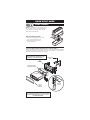
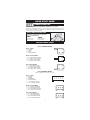
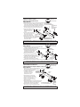
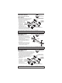
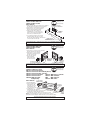
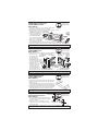
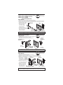
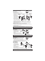
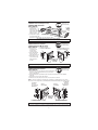
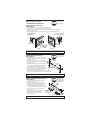
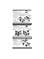
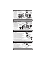
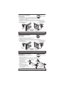
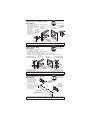
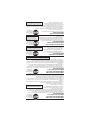
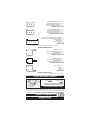
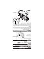
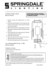
GUÍA RÁPIDA ENSAMBLE DEL ESTÉREO NOTA: La manga de montaje deberá quitarse primero del radio! Su radio puede ligarse con sus mangas. Deslice la manga de montaje (cubierta metálica) hacia fuera del radio por la parte trasera. SAQUE EL BORDE DEL ESTÉREO 1. Localice el mecanismo de traba en el borde de su radio DIN (típicamente) en el costado. 2. Deslice el borde de montaje hacia la parte de atrás del estéreo y sáquelo. ESTÉREO DE CARÁTULA PLANA DIN/ CARATULA SEPARABLE/EXTRAIBLE (DIN-E) Deslice la manga de montaje (cubierta metálica) hacia el espacio abierto del radio en el tablero y doble todas las lenguetas de montaje hacia afuera (vea el dibujo). Deslice el radio sobre las mangas de montaje una vez que haya sido asegurado al kit del tablero hasta que el radio se fije en su lugar. NOTA: EL SOPORTE DE LA PARTE TRASERA DEL RADIO LE AGREGA A LA INSTALACIÓN UNA MAYOR INTEGRACIÓN ESTRUCTURAL. TIRANTE DE SOPORTE POSTERIOR #1503 PANEL DE MONTAJE MONGA DE METÁLICA (INCLUIDOS CON ESTÉREO) ESTÉREO DIN DOBLE LAS LENGUETAS AGUERA MOLDURA SUMINISTRADA CON EL RADIO NOTA: LENGÜETAS RÁPIDAS DEL MONTAJE DEL EJE NO INCLUDIDAS. SI ESTÁ REQUERIDO PARA SU INSTALACIÓN ESTÉREA, LLAME (800) 621-3695 EXT. 3 PARA INMEDIATO. 5 GUÍA RÁPIDA ARMANDO CON ABRAZADERAS UNIVERSALES COLOCANDO EL SOPORTE UNIVERSAL INCLUIDO: (Si no dispone de soporte de fábrica) El tablero y abrazaderas de montaje incluidos tienen hoyos numerados y cada abrazadera esta etiquetada con una letra. Antes de adherir las abrazaderas con el tablero, siga las instrucciones de este manual para su vehículo. Las instrucciones para cada vehículo muestran que abrazaderas y hoyos deberán usarse para armar el kit. Una vez que Ud. identifique las abrazaderas y hoyos apropiados, ensámblelos como se indica en esta sección. Sujete al kit la abrazadera específica utilizando los aseguradores y tuercas que se incluyen. Inserte los aseguradores a través de la pared interior del kit, como se ilustra aquí. LOS NÚMEROS DE ORIFICIO Adhiera las abrazaderas al tablero de montaje ASEGURADOR DE ABRAZADERA ESTÁN VERTICAL utilizando el hardware de los aseguradores IMPRESOS EN LAS ORIFICIO DEL ABRAZADERAS y tuercas que se KIT NO. 6 incluyen en el kit. INTERIOR DE LA PARED DEL KIT B SOPORTE ABERTURA NO. 3 ASEGURADOR VERTICAL LOS NÚMEROS DE ORIFICIO DEL KIT ESTÁN IMPRESOS EN EL KIT UTILICE LAS LENGÜETAS SOMBREADAS Y ELIMINE LAS LENGÜETAS RESTANTES KIT PARA EL TABLERO ROMPER LA LENGÜETA EN LAS ORILLAS DE LA ABRAZADERA Vaya al ASEGURADOR VERTICAL ARMANDO CON ABRAZADERAS TRUCK/VAN/SUV Instale el soporte para Camionetas/4x4/Furgones a las paredes laterales GM1504 como se muestra, usando los pernos de cincho y tuercas provistas. Instale dos pernos para cada soporte en los orificios inferiores #2 #8 de cada soporte. Cada soporte tiene dos clavijas que se apoyan en los orificios #4 y #7. ABERTURA NO. 8 ASEGURADOR VERTICAL SOPORTE IZQUIERDA 2171 ABERTURA NO. 2 ASEGURADOR VERTICAL SOPORTE DERECHO 2171 Vaya al 4 GUÍA RÁPIDA ESCOJA SU VEHÍCULO Localice su vehículo en la tapa delantera de estas instrucciones y desarme el tablero. ¿RADIO ORIGINAL? ¿Su vehículo tiene la radio original? Si contesta SI, vaya al Si contesta NO, vaya al REMOCIÓN DE LAS ABRAZADERAS DE MONTAJE EN FÁBRICA En el caso de que su radio original se encuentre adherido al tablero con abrazaderas de montaje en fábrica, utilice la llave con socket de 10 mm para quitar la tuerca y la(s) abrazadera(s) como se indica. REMOCIÓN DEL ABRAZADERAS NOTA: El radio de fábrica puede tener abrazaderas a los lados, arriba y/o abajo. (véase la ilustración). ARMANDO CON ABRAZADERAS EN FÁBRICA PARTE SUPERIOR/PARTE INFERIOR Utilice los tornillos y tuercas de sostén que se incluyen, para adherir las abrazaderas de montaje de fábrica directamente al kit para el tablero, como se indica. NOTA: Si su abrazadera tiene pequeñas protuberancias, estas tendrán que lijarse o aplanarse con el objeto de que la abrazadera pueda montarse en la parte superior/inferior del kit (véase la ilustración). LATERALES Los adaptadores de abrazaderas de fábrica (FBA, por sus siglas en inglés) deberán adherirse a los lados derecho e izquierdo del kit, tal como se indica. Los indicadores de ubicación de los FBA deberán alinearse con los orificios marcados #1 a los lados del kit para el tablero. Utilice el hardware de los aseguradores y tuercas para su fijación. Repita para ambos lados. NOTA: Las abrazaderas en fábrica superiores e inferiores están atornilladas directamente en el kit. DOBLE LAS LENQUETAS AL MISMO NIVEL INDICADORES DE UBICACIÓN "FBA" ADAPTADOR DE ABRAZADERA DE FÁBRICA PERNO DE PORTE TUERCA HEXAGONAL DE SOSTEN ABRAZADERA PARA MONTAJE DE RADIO DE FÁBRICA Vaya al 3 GUÍA RÁPIDA INTRODUCCIÓN El kit de instalación en tablero Scosche para vehículos General Motors 1982-2002, le proporciona los componentes que Ud. necesitará para instalar su estéreo/tocacintas en el tablero de su vehículo. Siga las instrucciones particulares en este manual para quitar su radio automotriz instalado en fábrica. PRELIMINARES ANTES DE COMENZAR – LEA LA GUÍA RÁPIDA DE LAS PÁGINAS 2-4 PRECAUCIÓN: ANTES DE PROCEDER A LA INSTALACIÓN DESCONECTE LA TERMINAL NEGATIVA DE LA BATERÍA DE SU VEHÍCULO. SE RECOMIENDA LA UTILIZACIÓN DE UN MULTÍMETRO QUE MIDA VOLTS Y OHMS, EN LUGAR DEL PROBADOR SENCILLO DE LUZ ENCENDIDA CUANDO SE ESTÉ INSPECCIONANDO EL CABLEADO. EL PROBADOR DE LUZ ENCENDIDA (CON SENSOR DE CABLE A TIERRA) PUEDE CAUSAR DAÑOS A LA COMPUTADORA DE SU VEHÍCULO ASÍ COMO AL SISTEMA DE CABLEADO PARA EL DIAGNOSTICO EN CASO DE USARLO DE MANERA. • Ver las instrucciones del vehículo para determinar si se necesita alguna herramienta especial. • Leer todas las instrucciones que acompañan el estéreo/tocacasete del vehículo para el cableado y montaje apropiado. KITS UNIVERSALES SCOSCHE GM PARTS LIST: • • • • • • KIT PARA EL TABLERO HARDWARE ADAPTADORES DE ABRAZADERAS DE FÁBRICA ABRAZADERAS UNIVERSAL INSTRUCCIONES ABRAZADERAS CAMIÓN, VAN, Y SUV (No. 2171) 2 JUEGO DE INSTALACIÓN EN EL TABLERO PARA VEHÍCULOS DE GM1504/ GM1504W GENERAL MOTORS 1982-2005 BUICK 1982-96 1985-90 1992-94 1986-91 1991-94 1984-87 1995-99 1991-94 1982-89 1992-95 1983-85 CENTURY .................... 7 ELECTRA/PARK AVENUE....................... 7 LE SABRE .................... 7 LE SABRE .................... 7 PARK AVENUE ............ 7 REGAL ......................... 7 RIVIERA ....................... 7 ROADMASTER ............ 8 SKYHAWK ................... 8 SKYLARK..................... 8 SKYLARK..................... 8 CADILLAC 1982-88 1992-95 1985-91 1986-91 1984-85 2002 1999-02 1985-92 1986-91 1984-85 CIMARRON.................. 8 DEVILLE ....................... 9 DEVILLE ....................... 9 ELDORADO ................. 9 ELDORADO ................. 9 ESCALADE EXT ........... 9 ESCALADE .................. 9 FLEETWOOD ............... 9 SEVILLE ....................... 9 SEVILLE ....................... 9 CHEVROLET 1996-02 ASTRO ....................... 10 1990-95 ASTRO ....................... 10 1985-89 ASTRO ....................... 10 2001-02 AVALANCHE................ 9 1991-96 BERETTA ................... 10 1989-91 BLAZER, FULL SIZE .. 10 1997-02 CAMARO ................... 11 1993-96 CAMARO ................... 11 1982-92 CAMARO ................... 11 1994-96 CAPRICE CLASSIC ... 11 1991-93 CAPRICE/CAPRICE CLASSIC...................... 8 19851/2-90 CAVALIER RS, Z-24 .. 12 1982-90 CAVALIER ("VL" OR BASE MODELS)........... 8 CAVALIER .................. 12 CAVALIER .................. 12 CELEBRITY................ 12 CITATION................... 13 CORSICA ................... 10 CORVETTE ................ 13 CREW CAB DUALLY PICKUP........................ 9 1995-99 1991-94 1982-90 1985 1991-96 1984-89 1995-02 CHEVROLET (cont'd) CREW CAB DUALLY PICKUP........................ 9 CREW CAB DUALLY PICKUP...................... 10 JIMMY, FULL SIZE .... 10 PICKUP, FULL SIZE .... 9 S-15 JIMMY............... 15 S-15 JIMMY............... 15 S-15 JIMMY............... 15 S-15 PICKUP ............. 15 S-15 PICKUP ............. 15 SAFARI ...................... 10 SAFARI ...................... 10 SAFARI ...................... 10 SAVANA..................... 13 SONOMA PICKUP ..... 15 SUBURBAN ................. 9 SUBURBAN ............... 10 VAN, FULL SIZE ........ 15 YUKON XL ................... 9 YUKON ....................... 9 1989-91 1995-02 1998-01 1986-94 1982-85 1986-93 1982-85 1996-03 1990-95 1985-89 1996-00 1998-01 1995-99 1989-91 1988-95 2002 1995-02 CREW CAB DUALLY PICKUP...................... 10 EL CAMINO ............... 14 EXPRESS ................... 13 IMPALA SS ................ 11 LUMINA ..................... 13 LUMINA ..................... 13 LUMINA APV ............. 14 LUMINA APV ............. 14 MALIBU ..................... 14 MONTE CARLO ......... 13 MONTE CARLO ......... 14 NOVA ......................... 14 PICKUP, FULL SIZE .... 9 SUBURBAN ................. 9 SUBURBAN ............... 10 S-10 BLAZER ............ 15 S-10 BLAZER ............ 15 S-10 BLAZER ............ 15 S-10 PICKUP ............. 15 S-10 PICKUP ............. 15 S-10 PICKUP ............. 15 TAHOE ......................... 9 VAN, FULL SIZE ........ 15 VENTURE .................. 16 1986-87 1996-00 1994-96 1995-99 1990-94 1994-96 1990-93 1997-00 1995-99 1986-88 1985-88 1995-02 1995-02 1989-91 1998-01 1986-94 1982-85 1998-01 1986-93 1982-85 1995-02 1988-95 1997-99 1989-91 ISUZU 1998-00 HOMBRE PICKUP ..... 15 OLDSMOBILE 1992-95 1991-94 1985-91 1982-96 1989-94 1984-88 1986-88 1992-93 1989-91 1982-88 1984-93 1983-84 1997-99 1994-96 1990-93 1982-89 1989-93 ACHIEVA.................... 16 BRAVADA .................. 15 CUTLASS CALAIS ..... 16 CUTLASS CIERA ....... 16 CUTLASS SUPREME 17 CUTLASS SUPREME CLASSIC.................... 17 DELTA 88................... 17 EIGHTY-EIGHT ROYALE ..................... 17 EIGHTY-EIGHT ROYALE ..................... 17 FIRENZA .................... 11 NINETY-EIGHT .......... 17 OMEGA...................... 17 SILHOUETTE ............. 16 SILHOUETTE ............. 14 SILHOUETTE ............. 14 TORONADO............... 18 TOURING SEDAN...... 18 PONTIAC GMC 1995-02 1989-91 1992-99 1987-91 1984-88 1993-02 1985-92 1982-84 1996-98 1992-95 1985-91 1997-99 1994-96 1992-93 1982-88 1995-99 1997-99 1994-96 1990-93 1982-91 BONNEVILLE ............. 18 BONNEVILLE ............. 18 FIERO ........................ 18 FIREBIRD ................... 19 FIREBIRD ................... 19 FIREBIRD ................... 11 GRAND AM................ 19 GRAND AM................ 19 GRAND AM................ 19 GRAND PRIX ............. 20 GRAND PRIX ............. 20 GRAND PRIX ............. 20 SUNBIRD/J-2000 ........ 8 SUNFIRE/ CONVERTIBLE .......... 20 TRANS SPORT .......... 16 TRANS SPORT .......... 14 TRANS SPORT .......... 14 6000 ........................... 20 SATURN 1991-94 SC, SL, SL1, SL2 ....... 20 CAR STEREO CONNECTORS PROPORCIONA LA CONEXIÓN SENCILLA DE SU ESTÉREO AL ARNÉS DE CABLES DE FÁBRICA. 1988-up General Motors Vehicles 1978-87 General Motors Vehicles GMDA GM01 DESLINDE DE RESPONSABILIDAD Este manual de instrucciones está basado en información y estudios cuidadosamente documentados sobre el desmontaje de los paneles de instrumentos, arneses y códigos de cables e información pertinente a la instalación de este juego (GM1504) en los vehículos General Motors 1982-2005. Scosche Industries Inc. no puede ser responsable por discrepancias o inconsistencias debido a cambios u opciones que pueda hacer el fabricante del vehículo, ni por daños que pudiesen ocurrirle al automóvil durante la instalación de componentes debido al uso de este manual. Si usted tiene más preguntas, llame nuestro peaje liberta la línea técnica de ayuda en: 1-800-621-3695x3 © 2008 SCOSCHE INDUSTRIES, INC. SI 8/08 - GM1504/GM1504W (3000499)
This document in other languages
- español: Scosche GM1504W