1
X8SIE/X8SIE-F/X8SI6-F/X8SIE-LN4/X8SIE-LN4F User's Manual
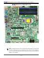
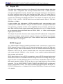
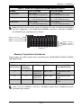
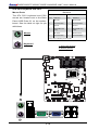
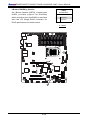
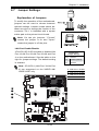
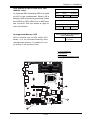
CMOS Clear
JBT1 is used to clear CMOS. Instead of pins, this "jumper" consists of contact pads
to prevent accidental clearing of CMOS. To clear CMOS, use a metal object such
as a small screwdriver to touch both pads at the same time to short the connection.
Always remove the AC power cord from the system before clearing CMOS.
Note: For an ATX power supply, you must completely shut down the system, remove
the AC power cord and then short JBT1 to clear CMOS.
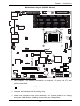
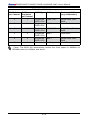
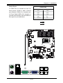
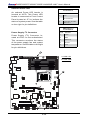
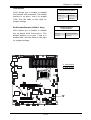
PCI Slot SMB Enable
PCI Slot_SMB Enable
Jumper Settings
Use Jumpers I2C1/I2C2 to enable PCI
Slot SMB (System Management Bus)
support to improve system management
for the PCI slots. See the table on the
right for jumper settings.
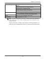
Jumper Setting
Definition
Short
Enabled
Open (Default)
Disabled
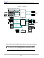
A. Clear CMOS
B. JI2C1
JPUSB1:B/P USB WAKE UP
1-2:ENABLE
2-3:DISABLE
4
1
JPI2C:PWR I2C
JPW1
JPW2
J12
1
KB/MOUSE
5
1
C. JI2C2
+
FLOPPY
DIMM1B
COM1
DIMM1A
DIMM2B
DIMM2A
DIMM2C
JPUSB1
DIMM1C
JAR:
PSU ALARM RST
1
FAN1
DDR3 1066/1333 UDIMM/RDIMM required
VGA
J28
CPU
FAN2
FAN5
JLED
JSPK
JF1
JPT1:
1-2:Enable
2-3:Disable
J5
A
FAN3
JPB:BMC
1-2:ENABLE
2-3:DISABLE
C
SW1
A
JPL4:LAN4
1-2:ENABLE
2-3:DISABLE
JI2C1/JI2C2
ON:Enable
OFF:Disable
LE5
UID
LED
PWR RST PWR OH/FF
ON
FAIL
UID
JPL4 JPL3
JPL2
JPL1
NIC2
JF1
NIC1
HDD PWR
LED LED
SPKR1
1
JPL1:LAN1
1-2:ENABLE
2-3:DISABLE
JPL2:LAN2
1-2:ENABLE
2-3:DISABLE
JPL3:LAN3
1-2:ENABLE
2-3:DISABLE
LAN2/LAN4
JLED1:Power LED
JSPK:Buzzer/Speaker
LAN1/LAN3
LE4
SLOT6 PCI-E 2.0 X16
JPB
NIC_LED3
NIC_LED4
B
JI2C1
JI2C2
C
T-SGPIO2
FAN4
JPB:
1-2:Enable
2-3:Disable
X8SIE
DESIGNED IN USA
REV:1.00
R1312
LE2
LE6
U2
JPG1: VGA
1-2:Enable
2-3:Disable
LE3
LE8
SAS0~3
SAS4~7
JS8
JS7
I-SATA2
Y2
LE7
JPG1
R572
U89
JPS1:SAS
1-2:Enable
2-3:Disable
J25
JIBTN
J8
JPS1
CMOS CLEAR
JBT1
SLOT2 PCI-E X4 on X8
I-SATA0
B1
USB4
D1
+
SLOT1 PCI 33MHZ
USB2/3
I-SATA3
JWOL
JL1
JWOL:
Wake on Lan
JL1:
Chassis Intrusion
DOM PWR
JWF1
J13
J14
COM2
USB10/11
I-SATA5
2-36
I-SATA4
USB5