1
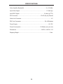
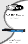
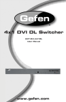
®
DVI 2500HD
Optical DVI Dual Link Extension
EXT-DVI-2500HD
User Manual
www.gefen.com
ASKING FOR ASSISTANCE
Technical Support:
Telephone
Fax
(818) 772-9100
(800) 545-6900
(818) 772-9120
Technical Support Hours:
8:00 AM to 5:00 PM Monday thru Friday PST
Write To:
Gefen Inc.
c/o Customer Service
20600 Nordhoff St
Chatsworth, CA 91311
www.gefen.com
[email protected]
Notice
Gefen, LLC reserves the right to make changes in the hardware, packaging and
any accompanying documentation without prior written notice.
DVI•2500HD is a trademark of Gefen, LLC.
© 2011 Gefen, LLC. All Rights Reserved
All trademarks are the property of their respective owners.
Rev A5
CONTENTS
1
Introduction
2
Operation Notes
3
Features
4
Sender Panel Layout
5
Sender Panel Descriptions
6
Receiver Panel Layout
7
Receiver Panel Descriptions
8
Connecting And Operating The DVI•2500HD
9
Connecting The DVI•2500HD In Direct DDC Mode
10 Connecting The DVI•2500HD In Virtual DDC Mode
11 Connecting The DVI•2500HD In Virtual DDC Mode
12 Specifications
13 Warranty
INTRODUCTION
Congratulations on your purchase of the DVI•2500HD. Your complete satisfaction
is very important to us.
Gefen
Gefen delivers innovative, progressive computer and electronics add-on solutions
that harness integration, extension, distribution and conversion technologies.
Gefen’s reliable, plug-and-play products supplement cross-platform computer
systems, professional audio/video environments and HDTV systems of all sizes
with hard-working solutions that are easy to implement and simple to operate.
The Gefen DVI•2500HD
The DVI•2500HD uses 4 fibers to extend Dual Link DVI display up to 6,600 feet
away from your source. Dual link DVI describes the use of all 24 pins of the DVI
(digital visual interface) connector to achieve super high resolutions.
How It Works
The DVI•2500HD Sender unit sits next to your computer. A short video
cable supplied with the DVI•2500HD system connects the DVI source to the
DVI•2500HD Sender unit. The DVI•2500HD Receiver unit sits next to your DVI
display and plugs into the DVI display’s Dual-Link DVI port. One CAT-5 cable and
a LC fiber optic cable (4-strand) connects the Sender and the Receiver units to
each other.
Note:
The CAT5 cable is for the transmission of DDC/EDID (video timing, resolution)
information, the Hot-plug signal and DC power. The fiber cable carries the video
picture information.
DVI Extension can be:
•
up to 500m (1640 feet) over Multi-mode fiber using Virtual DDC.
•
up to 2 km (6,600 feet) over Single-mode fiber using Virtual DDC.
•
up to 100m (330ft) with direct DDC using CAT5.
1
OPERATION NOTES
READ THESE NOTES BEFORE INSTALLING OR
OPERATING THE DVI•2500HD
•
LC terminated fiber optic cables (up to 2 pairs) are required for operation of
the DVI•2500HD system. A single CAT-5e cable will also be required when
operating in Direct DDC mode only.
•
This device will accept both Single-Mode and Multi-Mode fiber optic cables.
•
This device will accept both 50μ and 62.5μ multi-mode fiber optic cable
types.
•
The DVI•2500HD can operate in either Direct DDC (HDCP-Compliant) or
Virtual DDC modes. For a description of these modes, please see page 8.
•
Maximum extension in Direct DDC mode is 330 feet (100 meters) at a
maximum resolution of WUXGA (2560x1600/60Hz)
•
Maximum extension in Virtual DDC mode is 6,600 feet (2 kilometers) at a
maximum resolution of WUXGA (2560x1600/60Hz)
•
This device will accept both Single Link and Dual Link DVI type sources/
displays. Only 1 pair of LC cables, on Channel 1, are required when using
Single Link devices. A second pair is only required, on Channel 2, when
operating this device with Dual Link devices.
•
WARNING: Do not look directly into LC receptacles of the sending unit. This
device, however, does operate under the Laser Class I specification for eye
safety.
2
FEATURES
Features
•
Extends any dual link DVI compliant device up to 6,600 feet (2 km) from the
computer
•
Uses a 4 strand multimode LC-LC fiber optic cable; 2-strand/1-strand
(duplex) for Single-Link
•
Optionally use one CAT-5e cable for DDC and control signals
•
Supports HDTV resolutions such as 720p and 1080p
•
Supports up to 2560x1600 resolution at 60Hz refresh rate.
•
Supports DDWG standards for DVI compliant monitors
•
Supports Virtual DDC and DDC2B protocols
•
HDCP-Compliant in Direct DDC mode
Package Includes
(1) DVI•2500HD Sender
(1) DVI•2500HD Receiver
(2) 12V Power Supply
(1) 6ft DVI-DL Cable (M-M)
(1) Rack Ears
(1) User Manual
3
SENDER PANEL LAYOUT
Front Panel
1
2
3
4 5
Back Panel
6
7
8
4
9
10
SENDER PANEL DESCRIPTIONS
1
LED Power Indicator
This LED will become active once the included 5V DC power supply is properly
connected between the sender and an open wall power socket.
2
EDID Mode Selector Switch
This switch will set either the Direct DDC or Virtual DDC modes. For a
description of these modes please see page 8.
3
Self-EDID Button
This button will begin the EDID recording process when the DVI•2500HD is
operating in Virtual DDC mode. This button does not have any use in Direct
DDC mode.
4
EDID Program LED Indicator
This LED will become active after the Self-EDID button is pressed. This is to
indicate that the sending unit is ready to record the EDID of the connected DVIcapable device.
5
LED Status Indicator
This LED will become active once the DVI source device has been properly
connected and detected. This indicator will also become active when the
sending unit is ready to record EDID after the Self-EDID button is pressed.
6
12V DC Power Receptacle
This receptacle will require power from the included 12V DC power supply for
proper operation. Connect the included power supply between this port and an
open wall power socket.
7
DDC RJ45 Port
This port is used to connect a CAT-5e cable between the sending and receiving
units for DDC2B traffic. This cable is only necessary when the DVI•2500HD is
operating in Direct DDC mode.
8
DVI-D Input
This receptacle will accept either a DVI Single-Link or Dual-Link source device.
9
2 Port LC Fiber Receptacle (Channel 1)
This receptacle will accept 1 pair, or 2 single-strand, LC terminated fiber optic
cables. This cable is required at all times for operation.
10 2 Port LC Fiber Receptacle (Channel 2)
This receptacle will accept 1 pair, or 2 single-strand, LC terminated fiber optic
cables. This cable is only required for operation when Dual-Link sources are
used.
5
RECEIVER PANEL LAYOUT
Front Panel
1
2 3
Back Panel
4
5
6
6
7
8
RECEIVER PANEL DESCRIPTIONS
1
LED Power Indicator
This LED will become active once the included 5V DC power supply is properly
connected between the sender and an open wall power socket.
2
Channel 2 LED Link Indicator
This LED will become active once a link for Channel 2 has been established
between the sending and receiving units.
3
Channel 1 LED Link Indicator
This LED will become active once a link for Channel 1 has been established
between the sending and receiving units.
4
12V DC Power Receptacle
This receptacle will require power from the included 12V DC power supply for
proper operation. Connect the included power supply between this port and an
open wall power socket.
5
DDC RJ45 Port
This port is used to connect a CAT-5e cable between the sending and receiving
units for DDC2B traffic. This cable is only necessary when the DVI•2500HD is
operating in Direct DDC mode.
6
DVI-D Output
This receptacle will accept either a DVI-capable Single-Link or Dual-Link output
device (i.e. DVI display).
7
2 Port LC Fiber Receptacle (Channel 1)
This receptacle will accept 1 pair, or 2 single-strand, LC terminated fiber optic
cables. This cable is required at all times for operation.
8
2 Port LC Fiber Receptacle (Channel 2)
This receptacle will accept 1 pair, or 2 single-strand, LC terminated fiber optic
cables. This cable is only required for operation when Dual-Link sources are
used.
7
CONNECTING AND OPERATING THE DVI•2500HD
DDC Modes
DVI•2500HD can operate in 2 DDC modes. It is important to determine the DDC
mode before attempting to connect anything to the DVI•2500HD units. The DDC
will carry EDID information which is critical in determining a connected device’s
resolution capabilities and operational limits. This section will outline the 2 modes
and list the features of each.
Direct DDC Mode
The Direct DDC mode will transmit DDC2B, which will carry the EDID, over a
connected CAT-5e cable between the sending and receiving units. This mode
supports HDCP with a maximum extension distance of 330 feet (100 meters) .
Virtual DDC Mode
The Virtual DDC mode will record and store the EDID of a connected DVIcapable output device (i.e DVI display). This will permit the DVI extension to
reach a maximum distance of 6,600 feet (2 kilometers) as the distance will no
longer be limited to the CAT-5e cable used in Direct DDC mode. This mode does
not support HDCP.
Single-Link and Dual-Link Setups
DVI•2500HD will accept both Single-Link an Dual-Link DVI sources and displays.
When operating Single-Link devices, only a single pair of fiber optic cables will be
needed for operation. These cables will utilize Channel 1 for DVI extension.
When using Dual-Link devices, two pairs of fiber optic cables will be needed
for operation. These cables will utilize both Channel 1 and Channel 2 for DVI
extension.
8
CONNECTING THE DVI•2500HD IN DDC MODE
1.
Locate the DDC Mode switch on the front panel of the DVI•2500HD Sending
unit. Ensure that the switch is set to Direct DDC.
2.
Connect a DVI cable (one is supplied) between the DVI source device’s DVI
output and the DVI•2500HD Sending unit’s DVI input.
3.
Connect the DVI•2500HD Sending unit to the DVI•2500HD Receiving unit
using one of the options below:
•
Single-Link Devices - Using one pair of LC terminated fiber optic cable,
connect the Sending and Receiving units together using the Channel 1
connectors.
•
Dual-Link Devices - Using two pairs of LC terminated fiber optic cable,
connect the Sending and Receiving units together using both the
Channel 1 and Channel 2 connectors.
4.
Connect a CAT-5e cable between the DDC ports on the DVI•2500HD
Sending and Receiving units.
5.
Connect a DVI cable between the DVI•2500HD Receiving unit’s DVI output
and the DVI-capable output device’s (i.e. DVI display) DVI input.
6.
Connect both of the included 12V DC power supplies between the Sending
and Receiving units and open wall power sockets.
7.
Initialize (power on) the DVI-capable output device (i.e. DVI display) first,
then the DVI source device.
9
CONNECTING THE DVI•2500HD IN VIRTUAL DDC MODE
1.
Locate the DDC Mode switch on the front panel of the DVI•2500HD Sending
unit. Ensure that the switch is set to Virtual DDC.
2.
Record the DVI-capable output device’s (i.e. DVI display) EDID into the
DVI•2500HD Sending unit. The instructions below will use a computer
display with a DVI input as an example for a DVI-capable output device:
1.
Move the DVI•2500HD sending unit to the DVI display’s location or bring
the DVI display to the Sender’s location.
2.
Connect one of the included 12V DC power supplies between the
DVI•2500HD Sending unit and an open wall power socket.
3.
Press the Self-EDID button located on the front panel of the
DVI•2500HD Sending unit. The Status and EDID Program LED lights
should become active.
WARNING: The Self-EDID button must be pressed before attaching
the DVI-capable device (i.e. DVI display) to the sending unit for EDID
recording. Failure to do so may cause permanent damage to the
connected DVI device as unnecessary power may be supplied over
Pin-16.
4.
Connect a DVI cable (one is supplied) between the DVI display’s DVI
input and the DVI•2500HD Sender unit’s DVI input.
5.
Initialize (power on) the DVI display. The EDID Program will rapidly blink
while the EDID is being recorded. This process will take approximately 8
to 10 seconds. The recording will be complete when the EDID Program
LED turns off.
6.
Disconnect the DVI display from the DVI•2500HD Sending unit. Remove
the 12V power supply from the DVI•2500HD Sending unit.
7.
Return either the DVI•2500HD Sending unit or DVI display to its original
location.
3.
Connect a DVI cable (one is supplied) between the DVI source device’s DVI
output and the DVI•2500HD Sending unit’s DVI input.
4.
Connect the DVI•2500HD Sending unit to the DVI•2500HD Receiving unit
using one of the options below:
•
Single-Link Devices - Using one pair of LC terminated fiber optic cable,
connect the Sending and Receiving units together using the Channel 1
connectors.
•
Dual-Link Devices - Using two pairs of LC terminated fiber optic cable,
connect the Sending and Receiving units together using both the
Channel 1 and Channel 2 connectors.
10
CONNECTING THE DVI•2500HD IN VIRTUAL DDC MODE
5.
Connect a DVI cable between the DVI•2500HD Receiving unit’s DVI output
and the DVI-capable output device’s (i.e. DVI display) DVI input.
6.
Connect both of the included 12V DC power supplies between the Sending
and Receiving units and open wall power sockets.
7.
Initialize (power on) the DVI-capable output device (i.e. DVI display) first,
then the DVI source device.
11
SPECIFICATIONS
Video Amplifier Bandwidth ................................................................. 2 x 165 MHz
Input Video Signal .............................................................................. 1.2 Volts p-p
Input DDC Signal ......................................................................... 5 Volts p-p (TTL)
DVI Connector .................................................................... DVI-D (24 pin) Female
Video Link Connector ........................................................................................ LC
DDC Link Connector ...................................................................... RJ-45 Shielded
Power Supply ............................................................................................ 12V DC
Power Consumption ......................................................... 36 Watts (max. per unit)
Dimensions ......................................................................... 3.25”D x 4.25”W x 1”H
Shipping Weight ............................................................................................ 5 lbs.
12
WARRANTY
Gefen warrants the equipment it manufactures to be free from defects in material
and workmanship.
If equipment fails because of such defects and Gefen is notified within two (2)
years from the date of shipment, Gefen will, at its option, repair or replace the
equipment, provided that the equipment has not been subjected to mechanical,
electrical, or other abuse or modifications. Equipment that fails under conditions
other than those covered will be repaired at the current price of parts and labor in
effect at the time of repair. Such repairs are warranted for ninety (90) days from
the day of reshipment to the Buyer.
This warranty is in lieu of all other warranties expressed or implied, including
without limitation, any implied warranty or merchantability or fitness for any
particular purpose, all of which are expressly disclaimed.
1.
Proof of sale may be required in order to claim warranty.
2.
Customers outside the US are responsible for shipping charges to and from
Gefen.
3.
Copper cables are limited to a 30 day warranty and cables must be in their
original condition.
The information in this manual has been carefully checked and is believed to
be accurate. However, Gefen assumes no responsibility for any inaccuracies
that may be contained in this manual. In no event will Gefen be liable for
direct, indirect, special, incidental, or consequential damages resulting from
any defect or omission in this manual, even if advised of the possibility of such
damages. The technical information contained herein regarding the features and
specifications is subject to change without notice.
For the latest warranty coverage information, refer to the Warranty and Return
Policy under the Support section of the Gefen Web site at www.gefen.com.
PRODUCT REGISTRATION
Please register your product online by visiting the Register Product page
under the Support section of the Gefen Web site.
13
Rev A5
20600 Nordhoff St., Chatsworth CA 91311
1-800-545-6900
818-772-9100
www.gefen.com
Pb
This product uses UL listed power supplies.
fax: 818-772-9120
[email protected]