1
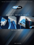
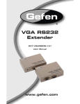
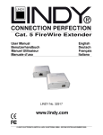
®
Firewire 800
Extender Plus
EXT-FW-1394BP
User Manual
www.gefen.com
ASKING FOR ASSISTANCE
Technical Support:
Telephone
(818) 772-9100
(800) 545-6900
Fax(818) 772-9120
Technical Support Hours:
8:00 AM to 5:00 PM Monday thru Friday PST
Write To:
Gefen, LLC
c/o Customer Service
20600 Nordhoff St
Chatsworth, CA 91311
www.gefen.com
[email protected]
Notice
Gefen, LLC reserves the right to make changes in the hardware, packaging and any
accompanying documentation without prior written notice.
Firewire 800 Extender Plus is a trademark of Gefen, LLC
© 2010 Gefen, LLC, All Rights Reserved
All trademarks are the property of their respective owners.
Rev A3
CONTENTS
1
Introduction
2
Operation Notes
3
Features
4
Sender Panel Layout
5
Sender Panel Descriptions
6
Receiver Panel Layout
7
Receiver Panel Descriptions
8
Connecting the Firewire 800 Extender Plus
8
Wiring Diagram
9
Specifications
10Warranty
INTRODUCTION
Congratulations on your purchase of the Firewire 800 Extender Plus. Your complete satisfaction is very important to us.
Gefen
Gefen delivers innovative, progressive computer and electronics add-on solutions that
harness integration, extension, distribution and conversion technologies. Gefen’s reliable,
plug-and-play products supplement cross-platform computer systems, professional audio/
video environments and HDTV systems of all sizes with hard-working solutions that are
easy to implement and simple to operate.
The Gefen Firewire 800 Extender Plus
This solution uses a sender and receiver system to instantly send your data from your
source to your extended Firewire device. It boasts a remarkable transfer rate of up to 980
Mbps and easily bridges distances up to 1640 feet (500 meters). This gives you the freedom to operate your computer based equipment and video cameras as if they were connected locally with no signal degradation or time lag. Receiving units have a second pair of
fiber connectors to daisy chain multiple Receiving units for extreme distances.
How It Works
Simply connect your computer to the Firewire Extender 800 sender unit with the supplied
cable. Connect your extended device to the receiver unit - up to 1640 feet away. One
2-strand LC-LC fiber optic cable, available in several lengths from Gefen, connect sender
(computer) to receiver (Firewire device).
1
OPERATION NOTES
READ THESE NOTES BEFORE INSTALLING OR
OPERATING THE FIREWIRE 800 EXTENDER PLUS
•
The fiber optics cable must be treated carefully when connectors are exposed. They
are susceptible to dust which can contribute to loss of pixels.
•
The Firewire 800 Extender Plus is housed in a metal box for better RF shielding.
•
Only LC terminated multi-mode fiber optic cable can be used with the Firewire 800
Extender Plus system.
•
Units can be cascaded up to 63 levels deep with a maximum distance between each
of 1640 feet (500 meters).
2
FEATURES
Features
•
Extends Firewire devices up to 1640 (500 meters) feet
•
Transfer Rates of 100/200/400/800 Mbps
•
Compliant with IEEE 1394a and 1394b
•
Allows remote devices to operate in real-time, connected to the source
•
Works with Apple and PC computers
•
Uses fiber optics to ensure long distance performance
•
Daisy chain multiple receivers for extreme distances
Package Includes
(1) Firewire 800 Extender Plus Sender
(1) Firewire 800 Extender Plus Receiver
(2) 3 ft. Firewire 400-to-800 cables (M-M)
(2) 3 ft. Firewire 800-to-800 cables (M-M)
(1) 12V DC Power supply
(1) Quick-Start Guide
3
SENDER PANEL LAYOUT
Front Panel
1
3
2
Back Panel
4
5
4
6
SENDER PANEL DESCRIPTIONS
1
Power LED
This LED will become active once the included power adapter has been connected.
2
Status LED
This LED will become active once a stable link has been established between the sending
and receiving units.
3
Fiber Optic TX and RX Inputs
Connect a LC terminated fiber optic cable for both the transmit (TX) and receive (RX)
signals between the Firewire 800 sending and receiving units.
4
12V DC Power Supply Input
Input for the supplied 12V DC power adapter.
5
Firewire Input
Connects to a Firewire hub, or Firewire device.
6
Firewire Input
Connects to a Firewire hub, or Firewire device.
5
RECEIVER PANEL LAYOUT
Front Panel
1
2
Back Panel
3
4
5
6
6
RECEIVER PANEL DESCRIPTIONS
1
Fiber Optic TX and RX Ports 1
Connect a LC terminated fiber optic cable for both the transmit (TX) and receive (RX)
signals between the Firewire 800 sending and receiving units. Optionally, this port can be
used for extension to another Receiving unit to extend the signal.
2
Fiber Optic TX and RX Ports 2
Connect a LC terminated fiber optic cable for both the transmit (TX) and receive (RX)
signals between the Firewire 800 sending and receiving units. Optionally, this port can be
used for extension to another Receiving unit to extend the signal.
3
12V DC Power Supply Input
Input for the supplied 12V DC power adapter.
4
Firewire Input
Connects to a Firewire hub, or Firewire device.
5
Power LED
This LED will become active once the included power adapter has been connected.
6
Status LED
This LED will become active once a stable link has been established between the sending
and receiving units.
7
CONNECTING THE FIREWIRE 800 EXTENDER PLUS
Connecting the Firewire 800 Extender Plus
1.
Connect the supplied Firewire cable from the computer’s Firewire port into one of the
firewire ports on the Firewire 800 Extender Plus Sending unit. The other port can be
used for a local Firewire device.
2.
Connect one pair of LC terminated fiber optic cables from the Firewire 800 Extender
Plus Sender unit to the Optical Port 1 on the Firewire 800 Extender Plus Receiving
unit.
NOTE: Additional Firewire 800 Extender Plus Receiving units can
be chained to reach further distances. To do this, connect another
pair of LC terminated fiber optic cables from the Optical Port 2 on
the Firewire 800 Extender Plus Receiving unit to the Optical Port 1
on another Firewire 800 Extender Plus Receiving unit.
3.
Connect your Firewire devices into the Firewire 800 Extender Plus Receiving unit at
the remote location.
4.
Plug the included 12 volt power supply into the Firewire 800 Extender Plus Receiving
unit at the remote location.
5.
Restart your computer only after you’ve made all the connections.
IMPORTANT: When selecting fiber optic cable, use only 50μ or
62.5μ multi-mode fiber optic cable.
Wiring Diagram
FIREWIRE 800
FIBER (2x)
(Up to 1650 ft)
Computer
Sender
Receiver 2
(Optional)
Firewire 800 Device
Receiver 1
Firewire 800 Device
EXT-FW-1394BP
8
SPECIFICATIONS
Input Connector Type .................................................................................................... 1394b
Output Connector Type ..................................................................................................1394b
Optical Specifications: ..................................................................IEEE1394b-2002 compliant
Link Connector: ...............................................................................................Duplex LC fiber
Fiber type: ..........................................................62.5 micron or 50.0 micron multi-mode fiber
Data rates: ......S100 (122.44 Mbps), S200 (245.76 Mbps), S400 (491.52 Mbps), S800
(983.04 Mbps)
Power Supply: ...............................................................................................External 12V DC
Power Consumption: ...........................................................36 watts (max) per power supply
Dimensions: .............................................................................................3.9”D x 0.9”H x 4”W
Shipping Weight ............................................................................................................. 3 Lbs
9
WARRANTY
Gefen warrants the equipment it manufactures to be free from defects in material and
workmanship.
If equipment fails because of such defects and Gefen is notified within two (2) years from
the date of shipment, Gefen will, at its option, repair or replace the equipment, provided
that the equipment has not been subjected to mechanical, electrical, or other abuse or
modifications. Equipment that fails under conditions other than those covered will be
repaired at the current price of parts and labor in effect at the time of repair. Such repairs
are warranted for ninety (90) days from the day of reshipment to the Buyer.
This warranty is in lieu of all other warranties expressed or implied, including without
limitation, any implied warranty or merchantability or fitness for any particular purpose, all of
which are expressly disclaimed.
1.
Proof of sale may be required in order to claim warranty.
2.
Customers outside the US are responsible for shipping charges to and from Gefen.
3.
Copper cables are limited to a 30 day warranty and cables must be in their original
condition.
The information in this manual has been carefully checked and is believed to be accurate.
However, Gefen assumes no responsibility for any inaccuracies that may be contained
in this manual. In no event will Gefen be liable for direct, indirect, special, incidental, or
consequential damages resulting from any defect or omission in this manual, even if
advised of the possibility of such damages. The technical information contained herein
regarding the features and specifications is subject to change without notice.
For the latest warranty coverage information, refer to the Warranty and Return Policy under
the Support section of the Gefen Web site at www.gefen.com.
PRODUCT REGISTRATION
Please register your product online by visiting the Register Product page under the
Support section of the Gefen Web site.
10
Rev A3
20600 Nordhoff St., Chatsworth CA 91311
1-800-545-6900
818-772-9100
www.gefen.com
Pb
This product uses UL listed or CE compliant power supplies.
fax: 818-772-9120
[email protected]