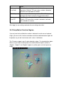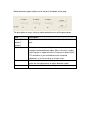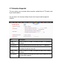
1
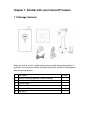
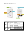
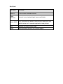
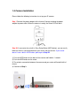
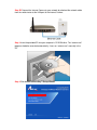
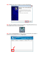
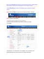
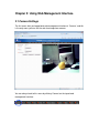
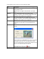
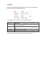
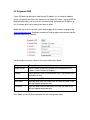
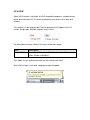
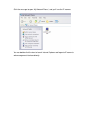
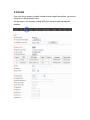
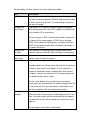
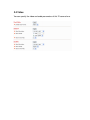
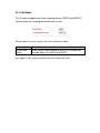
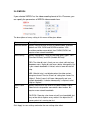
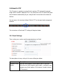
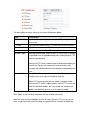
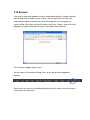
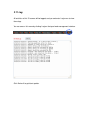
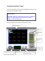
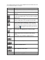
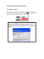
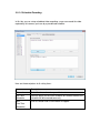
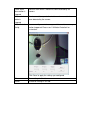
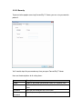
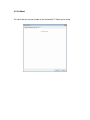
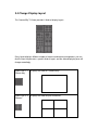
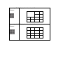
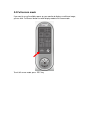
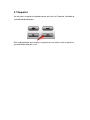
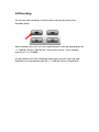
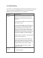
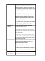
ConnectSky™600W
Wireless N MPEG4 Network Camera
Model # AIC600W
User’s Manual
Ver 1.0
Table of Contents
Chapter 1: Familiar with your Internet IP Camera ................................................................. 4
1.1 Package Contents..................................................................................................... 4
1.2 Basic Introduction ................................................................................................... 5
1.3 Product Highlights................................................................................................... 6
1.4 Familiar with Key Components ............................................................................... 7
1.5 Camera Installation.................................................................................................. 9
Chapter 2: Using Web Management Interface...................................................................... 15
2.1 Camera Settings..................................................................................................... 15
2.1.1 About .......................................................................................................... 17
2.2 LAN Settings......................................................................................................... 18
2.2.1 IP Address................................................................................................... 18
2.2.2 RTSP .......................................................................................................... 20
2.2.3 Dynamic DNS............................................................................................. 21
2.2.4 UPnP .......................................................................................................... 22
2.2.5 LoginFree ................................................................................................... 24
2.3 WLAN................................................................................................................... 25
2.4 Video..................................................................................................................... 30
2.4.1 Dual Mode .................................................................................................. 31
2.4.2 MPEG4....................................................................................................... 32
2.4.3 MJPEG ....................................................................................................... 33
2.5 Email & FTP ......................................................................................................... 34
2.5.1 Email Settings............................................................................................. 34
2.5.2 FTP Settings................................................................................................ 35
2.6 Motion Detection................................................................................................... 37
2.6.1 Basic Settings.............................................................................................. 37
2.6.2 Setup Motion Detection Regions................................................................. 38
2.7 Schedule Snapshot................................................................................................. 40
2.8 System................................................................................................................... 41
2.8.1 Camera Information .................................................................................... 41
2.8.2 Date / Time Setting ..................................................................................... 42
2.8.3 Utilities ....................................................................................................... 43
2.9 Status..................................................................................................................... 45
2.10 Account ............................................................................................................... 46
2.11 Log ...................................................................................................................... 48
Chapter 3: ConnectSky™ Viewer........................................................................................ 49
3.1 Software Installation.............................................................................................. 49
3.2 Using ConnectSky™ Viewer ................................................................................. 51
3.3 Configuring ConnectSky™ Viewer........................................................................ 54
3.3.1 Configure Cameras ..................................................................................... 54
3.3.2 General Settings.......................................................................................... 63
3.4 Change Display Layout ......................................................................................... 68
3.5 Full-screen mode ................................................................................................... 71
3.6 Scan....................................................................................................................... 72
3.7 Snapshot................................................................................................................ 73
3.8 Recording .............................................................................................................. 74
3.9 Video Playback...................................................................................................... 75
Chapter 4: Appendix ........................................................................................................... 76
4.1 Specification.......................................................................................................... 76
4.2 Troubleshooting..................................................................................................... 78
Technical Support ............................................................................................................... 81
Chapter 1: Familiar with your Internet IP Camera
1.1 Package Contents
Before you start to use this network camera, please check the package contents. If
anything is missing, please contact the dealer of purchase and return the package to
claim for missing contents.
Item Name
Quantity
1
Wireless N MPEG4 Network Camera AIC600W
1
2
Power Adapter 5V/1A
1
3
Ethernet Cable
1
4
Quick Installation Guide
1
5
Installation CD
1
6
Wall Mount
1
1.2 Basic Introduction
Thank you for purchasing ConnectSky™600W Wireless MPEG4 Network Camera!
This network camera AIC600W is an ideal product for all kinds of video-surveillance
purposes, like home/office safety, kid/pet monitoring, and remote video acquire etc.
Unlink conventional close-circuit vide camera, you’re not limited to the length of cable!
Once this camera is connected to Internet, you can receive video from anywhere in
the world where Internet access is available.
If you have problem installing a new cable from the place the camera is installed to
your monitoring computer, don’t worry! We also provide wireless version which
supports wireless network, that is, you can link to this camera wirelessly! You only
have to provide this camera with 5V power by the power adapter that comes with the
product package, and you don’t have to set a new network cable between the
network camera and monitoring computer.
Worry about the content will be intercepted by unauthorized person when the video is
transmitted over the air? That’s also not a problem! Unlink conventional analog
wireless camera, which video will be intercepted by anyone who got a compatible
video receiver, this network camera supports data encryption (WEP & WPA), which
will provide ultimate data security level. All video transmitted over the air is encrypted;
therefore no one will be able to get the video captured by the camera, expect yourself.
If you’re not familiar with wireless security setting, this camera also support WPS
(Wi-Fi Protected Setup), which allows you to setup wireless security in a very simple
way - just press a button or input a 8-digit number.
You can discover more useful functions in next section!
1.3 Product Highlights
•
No pre-loaded software required - all you need is a browser like Internet
Explorer 6 (and above, with plugin installed).
•
Supports VGA (640 x 480), QVGA (320 x 240), and QQVGA (160 x 120) video
resolution.
•
•
Supports two video compression format (MJPEG and MPEG4).
Wired and wireless network (802.11b / 802.11g / 802.11n) support.
•
Wireless data encryption (WEP / WPA).
•
WPS (Wi-Fi Protected Setup), the easiest way to setup a secure wireless
connection.
•
Supports DHCP and you can also assign a fixed IP address to the camera
also.
•
Supports Dynamic DNS (used to allocate the IP camera’s Internet address,
when the ISP you’re using does not assign you with a fixed Internet address).
•
Supports UPnP, Windows XP (and above) will discover this IP camera in
network neighbor automatically.
•
•
Send captured picture by Email or FTP when motion is detected.
Configurable motion detection sensitivity (6 levels from most sensitive to least
sensitive).
•
Built-in real-time clock, date and time information will be recorded with every
captured picture / video clip (also supports auto time synchronization via
network time protocol).
•
•
•
Upgradeable firmware - enjoy new functions without buying a new camera!
Supports up to 4 users, and you can set different password to different user.
Usage and event logging.
1.4 Familiar with Key Components
Front Panel LEDs
LED
Power /
WPS
Link
Color
Light Status
Description
On
The device is powered on.
Off
The device is powered off.
Blue
Green
Slow Blinking
Camera is booting
Quick Blinking
Camera is waiting for WPS connection
On
Camera is connected to network.
Off
Camera is not connected to network.
Flashing
Camera is logged in by user.
Back Panel
Item Name
Description
Antenna
2.4GHz Wireless Network Antenna
Tripod
Connector
Connects to any standard tripod / camera wall holder.
Reset / WPS
Press and release this button to activate WPS mode; press and
hold this button for 10 seconds to go back to factory default.
LAN
Connects to LAN by Ethernet cable.
Power
Power connector, connects to A/C power adapter.
1.5 Camera Installation
Please follow the following instructions to set up your IP camera.
Step 1 Connect the power adapter to the Internet Camera and plug the power
adapter to power outlet. When the camera is ready, the Power LED will be lit.
Step 2A If your router has a built in Easy Setup Button (WPS button), you can easily
build the wireless connection between your router and the camera. If your router
doesn’t have a built-in WPS button, please go to Step 2B.
1) Push the WPS button on the back of the camera and hold for 1 second.
2) Push the WPS button on the router.
3) The wireless connection between the camera and your router will be built within 1
minute.
4) Continue to Step 3.
Step 2B Connect the Internet Camera to your network by attached the network cable
from the switch/router to the LAN port of the Internet Camera.
Step 3 Insert the provided CD into your computer’s CD ROM drive. The “autorun.exe”
program should be executed automatically. If not, run “autorun.exe” manually in the
CD.
Step 4 Click Install ConnectSky™ Setup Wizard.
Step 5 Follow the on screen instructions to install the Setup Wizard.
Step 6 After the installation finished, the ConnectSky™ Setup Wizard will launch up.
If not, double click on the icon on your desktop:
Step 7 Click on Search Camera to show the camera(s) connected to your network. If
you do not see any camera in the list, try Step 2 again.
Step 8 Select the camera you wish to view/configure and click Browse Camera via
Web.
Note: By default, AIC600W uses dynamic IP address. If there is no DHCP server in
your network or you prefer to use static IP address, you may click Configure Camera
to change the IP settings.
Step 9 Enter ‘admin’ for both user name and password.
Step 10 Click on Install to install the plug-in for the camera.
Step 11 Click on the white box to install ActiveX control in order to view the camera
image.
Step 12 You should now be able to view the image.
Note: If you did Step 2A, your camera has connected to you wireless network already,
and you do not need any further configuration to start using your camera.
If you did Step 2B, please continue the following steps to configure the wireless
settings.
Step 13 Click on WLAN on the top menu bar to enter the Wireless LAN page.
Step 14 Follow the steps below:
1) Select the wireless network you wish to connect to
2) enter the wireless Key below if your wireless network is encrypted
3) click Apply.
3
1
2
Congratulations! The configuration is now complete. You can disconnect the
Ethernet cable from the camera and move it to the desired location.
Chapter 2: Using Web Management Interface
2.1 Camera Settings
The first menu after you logged onto web management interface is ‘Camera’, and this
is the only menu you can see the real-time image from camera.
You can always back to this menu by clicking ‘Camera’ on the top of web
management interface.
The descriptions of every setting in this menu will be given below:
Item
Description
Video Format
Specifies video encoding format. You can choose MPEG4 or
MJPEG (Motion-JPEG).
MPEG4 mode also supports motion detection (see chapter
2.2.1).
Snapshot
Take a snapshot picture and save the picture to your
computer’s hard drive. Click on directory display and you’ll be
prompted to select a folder to save snapshot file.
Record
Start video recording and save recorded video clip to your
computer’s hard drive. Click on directory display and you’ll be
prompted to select a folder to save snapshot file.
Full Screen
Click this button and the image captured by camera will be
displayed in full-screen mode. To resume, double-click the
image.
Digital Zoom
Click this button to enable digital zoom (video magnification)
function:
Check ‘Enable’ box to enable digital zoom, and you can set the
percentage of zoom from 100% (no magnification) to 400%.
You can also drag the green square by mouse and put it on the
area you wish captured image to be magnified.
Fit to Window
To exit digital zoom setting, press
button.
Click this button and captured image will fit to window size.
2.1.1 About
This function will provide you with the version number of current IP camera
plugin, which is useful when you need online support.
To see version information, right-click on the image. A pop-up menu will appear:
Select ‘About’ and the version information will appear:
2.2 LAN Settings
All network-related settings can be found in this menu, and you have to specify
TCP/IP parameters in this menu if you want to change IP address, use PPPoE,
Dynamic DNS, and activate UPnP function.
You can access this menu by clicking ‘LAN’ on the top of web management interface.
2.2.1 IP Address
You can define IP address and select the port number you wish to use here.
The descriptions of every setting in this menu will be given below:
Item
Description
Network Type
This camera can obtain the IP address from DHCP server
automatically (i.e. Router), or set a fixed IP address. Select
‘DHCP’ to obtain IP address automatically or ‘Static IP Address’
to assign this IP camera with a fixed IP address.
‘DHCP’ is enabled by default, so it is suggested to run the
ConnectSky™ Wizard to locate the camera and then assign a
fixed IP address to it.
IP Address
Specify the IP address for this IP camera here. The camera’s
default IP address is ‘192.168.2.240’.
Subnet Mask
Specify the subnet mask for this IP camera here.
Gateway
Specify the gateway address of the local network here.
Primary DNS
Specify the IP address of DNS server here. Please input IP
address only. If you don’t know the address of DNS server, ask
network administrator or your ISP for help.
Secondary DNS
Specify the IP address of backup DNS server here. When
primary DNS is unreachable, IP camera will use the IP address
specified here as DNS server.
This field is optional.
AV Control Port
Specify the port number of video transfer here. If you have
firewall on your network, you need to allow computers on
Internet to access this port number of the IP address of IP
camera, or you’ll not be able to view video from Internet.
HTTP Port
Specify the port number of web management interface here. If
it’s not 80, you’ll have to add ‘:port’ after the IP address /
hostname of this IP camera.
For example, if the HTTP port number you specified here is 90
and the IP address of IP camera is 10.20.20.30, then you have
to input ‘http://10.20.20.30:90’
in the address bar of Internet explorer.
Click ‘Apply’ to save settings and make the new settings take effect.
2.2.2 RTSP
RTSP (Real-Time Streaming Protocol) allows you to view live video captured by IP
camera. You can set RTSP related settings here.
The descriptions of every setting in this menu will be given below:
Item
Description
Enable RTSP
Select ‘Enable’ to activate RTSP function of this IP camera,
select ‘Disable’ to disable it.
RTSP Port
Input the port number which RTSP will use. Default setting is
554.
RTSP Path
Input the path of RTSP stream. **
RTP Port Range
Input the port range of RTP. Default setting is 50000 to 60000.
Click ‘Apply’ to save settings and make the new settings take effect.
2.2.3 Dynamic DNS
If your ISP does not give you a fixed Internet IP address (i.e. the Internet address
you’re using when you access the Internet is not always the same – ask your ISP for
detailed information), you can use this function to help you locate the IP address of
this IP camera when you’re away from home or office.
Before you can use this function, you’ll need to apply for an account at dyndns.org
(http://www.dyndns.org). Detailed instructions of how to apply a new account can be
found on dyndns.org’s website.
The descriptions of every setting in this menu will be given below:
Item
Description
Enable DDNS
Select ‘Enable’ to activate Dynamic DNS function of this IP
camera, select ‘Disable’ to disable it.
Provider
Select dynamic DNS service provider here. Only dyndns.org is
available currently.
Host Name
Input dynamic DNS host name here.
User Name
Input dynamic DNS user name here, must be the same as the
one you applied on dyndns.org.
Password
Input dynamic DNS password here, must be the same as the
one you applied on dyndns.org.
Click ‘Apply’ to save settings and make the new settings take effect.
2.2.4 UPnP
When UPnP function is activated, all UPnP-compatible computers / network devices
will be able to discover this IP camera automatically (only those in the same local
network).
This function is useful and you don’t have to remember the IP address of this IP
camera. Simply open ‘Network neighbor’ and it’s there!
The descriptions of every setting in this menu will be given below:
Item
Description
Enable UPnP
Select ‘Enable’ to activate UPnP function of this IP camera,
select ‘Disable’ to disable it.
Click ‘Apply’ to save settings and make the new settings take effect.
After UPnP function is activated, a popup message will appear:
Click the message to open ‘My Network Places’, and you’ll see the IP camera:
You can double-click the icon to launch Internet Explorer and log onto IP camera’s
web management interface directly.
2.2.5 LoginFree
You can specify a filename here, and everyone who know this filename can
gain access to the picture captured by the IP camera with this name with .jpg
file extension.
For example, if the filename you specified here is ‘loginfree’ and your IP
camera’s IP address is ‘192.168.2.240’, then everyone on the network can
access to the picture taken by the IP camera at
‘http://192.168.2.240/loginfree.jpg’.
This function is for convenience only, and anyone who knows this filename will
be able to see the picture taken by your IP camera. Please think again before
you use this function.
The descriptions of every setting in this menu will be given below:
Item
Description
LoginFree
Specify the file name of the picture here. If you want to disable
this function, leave it blank.
Click ‘Apply’ to save settings and make the new settings take effect.
2.3 WLAN
If you wish to use wireless network instead of wired network connection, you have to
set wireless LAN parameters here.
You can access this menu by clicking ‘WLAN’ on the top of web management
interface.
The descriptions of every setting in this menu will be given below:
Item
Description
Self PinCode
A random 8-digit code will be displayed here. If the wireless AP
you wish to connect supports PINCODE, please input this code
to the AP you wish to connect. This code changes every time
you enter this page.
Configure via
Push Button
If the wireless AP you wish to connect supports push button
WPS configuration, click ‘Start PBC’ and press the WPS button
on the wireless AP to start pairing.
You can also press ‘WPS / Reset’ button located at the back of
IP camera for the same purpose. DO NOT press and hold
‘WPS / Reset’ button for too long time, if you press and hold
‘WPS / Reset’ button for more than 10 seconds, all settings in
IP camera will be lost!
Configure via
PinCode
If the wireless AP already generates a 8-digit code, please
input the code here and click ‘Start PIN’ button to start pairing.
Wireless
Connection
Select ‘Enable’ to activate wireless network function of this IP
camera, select ‘Disable’ to disable it.
Network Type
Select the network type of wireless connection.
Available options are ‘Infrastructure’ (Connect the IP camera to
a wireless access point), and ‘Adhoc’ (This IP camera will
become a stand-alone wireless network point, other wireless
computers / devices can discover this IP camera and connect
to it without wireless access point).
You can set to ‘Adhoc’ when you don’t have any wireless
access point, but your computer has wireless network card. Set
to ‘Infrastructure’ when you have wireless access point, and
you have computers with wired network connection.
Available
Networks
Here shows all wireless access points found by this IP camera.
Please note not all access points will be displayed at the same
time, if the access point you wish to connect does not appear,
you may have to click ‘Refresh’ button for several times until it
appears.
The descriptions of all fields is listed below:
Connect: You can select the wireless access point you wish to
connect here.**
SSID: the SSID of all found wireless access points will be
shown here. Some wireless access point may hide their
SSID, in this case, you have to identify them by their MAC
address.
MAC Address: If you there are many wireless access points in
proximity or some wireless access point hides it’s SSID, you
can use MAC address to distinguish them.
Signal: Shows the radio signal strength in percent.
Channel: Shows the radio channel of this wireless access
point.
Encryption: Shows the encryption type used by this wireless
access point. You must use the same encryption type if you
wish to connect to a certain wireless access point. If the
wireless access point does not use encryption, ‘Disabled’ will
be displayed here.
Network Type: Shows the network type of a certain wireless
access point (Infrastructure or Adhoc).
SSID
Input the SSID of the wireless access point you wish to
connect. It should be less than 32 alphanumerical characters.
When you select a wireless access point above, it’s SSID will
be filled in this field automatically. However, if the SSID is not
displayed (the wireless access point you selected choose to
hide it’s SSID), you have to know it’s SSID and input it here, or
you will not be able to connect it.
Channel
Select the radio channel you wish to use here. When network
type is ‘Infrastructure’, the radio channel is auto-selected
according to the channel that wireless access point uses. You
can only select the channel number when network type is
‘Adhoc’.
Basic Rate
Select the maximum wireless data transfer rate here, from
1Mbps to 54Mbps. Maximum transfer rate for 802.11b wireless
network is 11Mbps, and maximum transfer rate for 802.11g
wireless network is 54Mbps.
It’s recommended to select ‘Auto’, so the data transfer rate will
vary (up to 150Mbps) according to the actual signal strength
and quality.
Authentication
Select the wireless authentication here, and this setting must
be the same with the wireless access point you selected.
When you select a wireless access point from the list, it’s
authentication type will be selected automatically, and you
should not modify it or you will not be able to connect to the
wireless access point you selected.
Available options are: None (no wireless security), Open
System, Shared Key System, WPA-PSK, WPA2-PSK.
Encryption Type
Select the wireless encryption type here, and this setting must
be the same with the wireless access point you selected.
When you select a wireless access point from the list, it’s
encryption type will be selected automatically, and you should
not modify it or you will not be able to connect to the wireless
access point you selected.
Available options are: None, WEP, TKIP and AES. The options
available here will vary depends on the authentication type you
selected above. If an authentication type does not support need
encryption, this field will be grayed out.
WPA Pre-Shared
Key
Input the WPA pre-shared key here.
This field is only available when authentication type is
WPA-PSK or WPA2-PSK, and will be grayed out when other
authentication type is selected.
WEP Key Length
Please select the key length when you use WEP encryption.
Available options are 64-bit and 128-bit.
Selecting ‘128-Bit’ is safer, however, it would make the network
a little bit slower.
If the key length is 64-bit, you should input 10 HEX characters
or 5 ASCII characters, like 112233aabb (HEX) or MYWEP
(ASCII).
If the key length is 128-bit, you should input 26 HEX characters
or 13 ASCII characters, like 11223344556677889900abcdef
(HEX) or myweppassword (ASCII).
WEP Key Format Select the Key Format of WEP key here. Available options are
‘HEX’ and ‘ASCII’.
When you select ‘HEX’ WEP key format, you can only use
numbers (0 to 9), and alphabet a to f as WEP key; when you
select ‘ASCII’ WEP key format, you can use all alphanumerical
characters, and is case sensitive.
Default Key
Select the default key set that the IP camera should use
against the wireless access point when WEP encryption is
used.
Available options are 1 to 4.
WEP Key 1
Input the 1st set of WEP key here. At least a set of WEP key is
required if you use WEP as Authentication.
You should enter the key value into WEP Key 1 if you only have
one key.
WEP Key 2
Input the 2nd set of WEP key here.
WEP Key 3
Input the 3rd set of WEP key here.
WEP Key 4
Input the 4th set of WEP key here.
Click ‘Apply’ to save settings and make the new settings take effect.
2.4 Video
You can specify the video and audio parameters of this IP camera here.
2.4.1 Dual Mode
This IP camera supports two video encoding formats: MPEG4 and MJPEG.
You can select the encoding format from one of them.
The descriptions of every setting in this menu will be given below:
Item
Description
Default Video
Format
Specify default video encoding format of this IP camera here.
Available options are MPEG4 and MJPEG.
Click ‘Apply’ to save settings and make the new settings take effect.
2.4.2 MPEG4
If you selected ‘MPEG4’ as the video encoding format of this IP camera, you
can specify the parameters of MPEG4 video encoder here.
The descriptions of every setting in this menu will be given below:
Item
Description
Video Resolution
Specify video resolution of MPEG4 video encoder. Available
options are VGA, QVGA and QQVGA resolution. VGA
resolution provides more details than QVGA/QQVGA, but
requires more network bandwidth.
Video Quality
Specify video quality. There are two video quality types: CBR
(Constant Bit Rate), and VBR (Variable Bit Rate):
CBR: The video bit rate is fixed, you can select a bit rate from
dropdown menu. Higher bit rate means better video quality. But
if your network bandwidth is limited, select a lower bit rate will
help.
Video Frame
Rate
VBR: Video bit rate is variable based on the video content
being transferred. There’re 5 levels of setting from ‘Lowest’ to
‘Highest’. Select ‘Lowest’ will lower video quality and save
network bandwidth; if a better video quality is required, select
‘High’ or ‘Highest’.
Specify video refresh rate of MPEG4 video encoder. Higher
video refresh rate provides more details about motion, but
requires more network bandwidth.
CAUTION: Choosing a low frame rate will save bandwidth, but
may not be able to capture every motion if the object that IP
camera points to is moving too fast.
Click ‘Apply’ to save settings and make the new settings take effect.
2.4.3 MJPEG
If you selected ‘MJPEG’ as the video encoding format of this IP camera, you
can specify the parameters of MPEG4 video encoder here.
The descriptions of every setting in this menu will be given below:
Item
Description
Video Resolution
Specify video resolution of MJPEG video encoder. Available
options are VGA, QVGA, and QQVGA resolution. VGA
resolution provides more details than QVGA and QQVGA, but
requires more network bandwidth.
Video Quality
Specify video encoding quality of MJPEG video encoder. There
are five levels of video quality from highest to lowest. Higher
video quality provides better video quality, but requires more
network bandwidth.
Video Frame
Rate
Specify video refresh rate of MJPEG video encoder. Higher
video refresh rate provides more details about motion, but
requires more network bandwidth.
CAUTION: Choosing a low frame rate will save bandwidth, but
may not be able to capture every motion if the object that IP
camera points to is moving fast.
Click ‘Apply’ to save settings and make the new settings take effect.
2.5 Email & FTP
This IP camera is capable to send an Email or perform FTP upload with captured
image, when a motion is detected. This is very convenient since IP camera will guard
the environment automatically for you, and you don’t have to look at the monitor all
the time.
You can access this menu by clicking ‘E-Mail & FTP’ on the top of web management
interface.
The instructions of Email and FTP settings will be given below.
2.5.1 Email Settings
These settings are used to send the captured picture via Email:
The descriptions of every setting in this menu will be given below:
Item
Description
Recipient E-Mail
Address
Input the email recipient’s Email address here. If you have
more than one Email recipient, please add a ; (semicolon) mark
between every Email address. All characters shouldn’t exceed
127 characters.
SMTP Server
Input the IP address or host name of the SMTP server (the
server that delivers the Email for you) here.
If you don’t know, please refer to the SMTP server you’re using
in your Email software (i.e. Microsoft Outlook), or ask your
network administrator or ISP.
SMTP Port
Input mail server’s SMTP port here. Most of mail servers use
port number 25.
Sender E-Mail
Address
Input the Email address of mail sender, this will help you to
identify the Email sent by this IP camera by sender’s Email
address.
NOTE: Some mail server would reject to deliver the Email from
unknown sender, it’s recommended to input your own Email
address here, or any other actual one.
SMTP
Authentication
Some SMTP server requires mail senders to be authenticated
before they can send Email. If your SMTP server requires you
to do so, please select ‘Enable’, or select ‘Disable’ to disable it.
If you don’t know, please refer to the SMTP server you’re using
in your Email software (i.e. Microsoft Outlook), or ask your
network administrator or ISP.
User Name
Please input the user name of SMTP server here, if your SMTP
server requires the use of authentication.
Password
Please input the password of SMTP server here, if your SMTP
server requires the use of authentication.
Click ‘Apply’ to save settings and make the new settings take effect.
After that, you can click ‘Send a test email’ to send a testing Email to the address you
set here, so you can make sure the setting you specified here is correct and working.
2.5.2 FTP Settings
These settings are used to send the captured picture by FTP:
The descriptions of every setting in this menu will be given below:
Item
Description
FTP Server
Input the IP address or host name of the FTP server you wish
to use here.
FTP Port
Input the port number of the FTP server you wish to use here.
User Name
Input the user name of the FTP server you wish to use here.
Password
Input the password of the FTP server you wish to use here.
Remote Folder
Input the remote folder name on the FTP server here. If nothing
is specified here, all uploaded image files will be placed in FTP
server’s root directory.
Please ask FTP server’s administrator to know which folder you
should use. Certain user name may have restrictions and
therefore can not place the file in the directory not owned by the
user.
Passive Mode
Select ‘Enable’ to use passive mode to send file, or select
‘Disable’ to not to use passive mode to send file.
Some FTP servers require passive mode, if you don’t know,
please ask FTP server’s administrator; most of FTP servers will
work fine with both modes, but if you found that non-passive
mode is not working, you can try to use passive mode.
Click ‘Apply’ to save settings and make the new settings take effect.
After that, you can click ‘Upload a test file’ to send a file to the FTP server you set
here, so you can make sure the setting you specified here is correct and working.
2.6 Motion Detection
2.6.1 Basic Settings
Motion detection function makes this IP camera become your non-stop guard. You
don’t have to waste time monitoring the images from the camera, yet it will detect all
motions for you. Once motion is detected, a captured image will be sent to you by
Email or via FTP.
You can access this menu by clicking ‘Motion Detection’ on the top of web
management interface.
The descriptions of every setting in this menu will be given below:
Item
Description
Motion Detection
Enable
Select ‘Enable’ to start motion detection, and select ‘Disable’ to
disabled it.
Next Event
Detected Interval
Specify the time interval between two motion detections in
seconds. If a motion is detected after last detection time, and
before next detection time, nothing will be send by Email or via
FTP.
Please specify a time interval that suites your need. If the time
interval is too long, you may not be able to know what is
happened between time interval; if the time interval is too short,
you may receive too many unnecessary images or it may
consume too much storage spaces on Email and / or FTP
server.
Send snapshot
file to Email
Select ‘Yes’ to send a picture to the Email address you
specified in ‘E-Mail & FTP’ menu when a motion is detection,
and select ‘No’ to disable this function.
E-Mail Subject
Set the subject of Email being sent here. This will help you to
distinguish the Email sent by this IP camera from others.
Send snapshot
file to FTP
Select ‘Yes’ to send a picture to the FTP server you specified in
‘E-Mail & FTP’ menu when a motion is detection, and select
‘No’ to disable this function.
Click ‘Apply’ to save settings and make the new settings take effect.
2.6.2 Setup Motion Detection Regions
If you only want to be notified when motion is detected in certain area of captured
image, you can use this function and motions outside of motion detection region will
be ignored, so you won’t receive too much ‘useless’ notifications.
This IP camera supports up to 3 motion detection regions. To setup detection region,
Please use your mouse to drag and resize motion detection regions marked as
‘Region1’, ‘Region2’, and ‘Region3’ (appear as yellow, green, and red squares on
image:
Motion detection region settings can be found at the bottom of this page:
The descriptions of every setting in motion detection menu will be given below:
Item
Description
Region1 /
Region2 /
Region3
Check the box to enable / disable a certain motion detection
area.
Sensitivity
Control the detection sensitivity of motion detection of
respective motion detection region. When sensitivity is higher,
small changes in image will cause IP camera to send a Email /
FTP notification; if you received too much unwanted
notification, try to set sensitivity to a lower value.
Refresh
Click this button to take and display a new picture so you can
make real-time adjustments to motion detection region.
Save
Save current motion detection settings.
2.7 Schedule Snapshot
This menu allows you to schedule taking snapshots, upload them to FTP and/or send
to your email address.
You can access this menu by clicking ‘System’ on the top of web management
interface.
Item
Description
Enable FTP
Schedule
Select ‘Enable’ or ‘Disable’ to enable or disable FTP uploading
schedule.
Time Interval
You can specify the desired time interval for FTP uploading.
File Control
Upload files with filename composed of date / time
Overwrite file with the same file.
Enable E-Mail
Schedule
Select ‘Enable’ or ‘Disable’ to enable or disable Email sending
schedule.
Time Interval
You can specify the desired time interval for the camera to send
an Email with snapshot.
2.8 System
The system menu allows you to set some system-specific parameters, like password
and time setting. You can also upgrade the firmware of this IP camera, to make new
functions available on this IP camera. You may also clear all settings or reboot the IP
camera here.
You can access this menu by clicking ‘System’ on the top of web management
interface.
2.8.1 Camera Information
Camera information allows you to set the name and administrator’s password of this
camera.
The descriptions of every setting in this menu will be given below:
Item
Description
Camera Name
Please specify the name of this IP Camera here. This can be
used to identify your camera on the network when you have
more than one IP camera in the same network.
Default name begins with ‘AIC600W-‘ plus the last 6 characters
of the MAC address of this IP camera. You can modify the
name to the one you can remember and meaningful to you, but
never give all IP cameras in the same network with same
name.
Password
Please specify the administrator’s password here. (The one
you need when you log onto web management interface and
use ‘admin’ as user name.
Confirm
Password
Please input the same password again, to make sure there’s no
typo.
Click ‘Apply’ to save settings and make the new settings take effect.
2.8.2 Date / Time Setting
This setting allows you to change the date and time of the real time clock in this IP
camera. You can set the time manually, or use network time protocol (NTP) to set
the time automatically.
The descriptions of every setting in this menu will be given below:
Item
Description
Set Date/Time
manually
Please input the date and time you wish to set here.
Date / time format is YYYY / MM / DD HH:MM:SS
Time is in 24-hour format.
You can click ‘Synchronize to PC time’ to use the time of the
computer you’re using.
Example: 24th August 2007 = 2007/ 08 / 24,
and PM 9:24:30 = 21:24:30
Time Zone
Please select the time zone of the country / city of resident from
dropdown menu here.
NTP Server
Please input the IP address or host name of NTP server here.
You can use default value ‘pool.ntp.org’, or ask your ISP for the
IP address or host name, if they have one.
Enable Daylight
Saving Time
Select ‘Yes’ if your area of residence uses daylight saving; if
not, select ‘No’.
Synchronize to
PC time
Click this button and the IP camera will use the current time
setting of your computer as IP camera’s time setting.
Click ‘Apply’ to save settings and make the new settings take effect.
2.8.3 Utilities
This menu allows you to upgrade firmware, clear all settings, reboot the IP camera,
and switch LED lights on/off.
The descriptions of every setting in this menu will be given below:
Item
Description
Upgrade
Firmware
If you downloaded latest firmware file from our website, you
can click ‘Browse’ button to pick the firmware file you wish to
use. Then click ‘Upgrade’ button to start firmware upgrade
procedure.
It’s recommended to use wired Ethernet connection when you
use this function, and DO NOT DISCONNECT OR CLOSE
WEB BROWSER DURING UPGRADE!
Reset to Factory
Defaults
Clear all settings in the camera. Please think again before you
do this, and then click this button to reset all settings.
NOTE: IP address will be reset to default value ‘192.168.2.240’
also. You’ll need to change the IP address setting of your
computer if the IP address of your computer does not begin
with ‘192.168.2’, and subnet mask is not ‘255.255.255.0’, or
you’ll not be able to connect to this IP camera again.
Reboot Device
If you found the IP camera is responding slowly or behaves
strange, you can click this button to try to reboot the IP camera,
this may help.
LED Setting
Switch the LED light of this IP camera off, so ‘LAN’ and ‘WLAN’
LED on the IP camera will stop working, in case you don’t want
other people know the camera is transferring data.
You can click this button again to switch LED lights on again.
2.9 Status
This menu provides all information about this IP camera, like firmware version,
system uptime, date / time, and network information.
You can access this menu by clicking ‘Status’ on the top of web management
interface.
2.10 Account
If you wish to allow other people to view the image captured by this camera, but don’t
want to allow them to modify system settings, you can give them user-level user
name and password, so they can only view the image and can not change any
system setting. When they want to click menus other than ‘Camera’, they will see the
following message informing that they don’t have permission to do that:
This IP camera supports up to 4 users.
You can access this menu by clicking ‘Users’ on the top of web management
interface.
Please note: only one user (including administrator) will be able to view the image of
IP camera at the same time.
The descriptions of every setting in this menu will be given below:
Item
Description
Login
Specify the user name here. Please use alphanumerical
characters (0 to 9, A to Z, and a to z). Not using symbols and
space.
Password
Specify the password for this user here.
Confirm
Password
Specify the password for this user here again.
Authority
Select ‘Operator’ or ‘Guest’ to grant authority to different users.
Add
After filling up Login, Password and Confirm password, click
‘Add’ to add the user account.
Modify
Select a user account you want to modify from the list, change
the information and click ‘Modify’ to apply the change.
Remove
Select a user account you want to remove from the list, change
the information and click ‘remove’.
2.11 Log
All activities of this IP camera will be logged, and you and enter ‘Log’ menu to view
these logs.
You can access this menu by clicking ‘Log’ on the top of web management interface.
Click ‘Refresh’ to get latest update.
Chapter 3: ConnectSky™ Viewer
3.1 Software Installation
The ConnectSky™ Viewer provides various functions like video recording, after this
software is installed, you can use your IP camera to safeguard your property. Please
follow the instructions below to install the software.
Step 1 Insert the provided CD into your computer’s CD ROM drive. The “autorun.exe”
program should be executed automatically. If not, run “autorun.exe” manually in the
CD.
Step 2 Click Install ConnectSky™ Viewer.
Step 3 Click ‘Next’ to continue. Please follow the on screen instructions to finish the
installation.
Step 4 Please click ‘Finish’ to finish the procedure (ConnectSky™ Viewer will start
after you click ‘Finish’ button, if you want to start it later, uncheck ‘Launch IPCam
Surveillance Software’ box).
3.2 Using ConnectSky™ Viewer
You can click ‘ConnectSky™ Viewer’ icon from desktop, quick launch bar, or start
menu to start the ConnectSky™ Viewer.
Before you start:
ConnectSky™ Viewer will only work when your monitor’s resolution is
‘1024 x 768’. Please change the resolution before you use this
software, or it won’t be able to start.
Here are descriptions for all components of ConnectSky™ Viewer:
Video displaying area
Language
Display
layout
Full screen /
Scan
Pan Tilt Control
(Not Applicable)
Exit / Minimize window
Message display box
Recording / System configure
Playback / Snap shot
You can put the mouse cursor on a certain component and see its button name, and
here’re detailed descriptions of all buttons:
Item
Description
Video displaying
The image of all connected cameras will be displayed here.
area
Language
Select a language from this dropdown menu to change display
language.
Display layout
Change camera image display layout (Click a layout icon to
change camera display layout). There are 8 kinds of available
display layouts.
Full screen
Click this button to switch to full screen mode (only display all
camera’s image), press ‘ESC’ key to quit full screen mode.
Scan
Click this button and the ConnectSky™ Viewer will switch
displaying the image of all connected camera automatically.
Click this button once to activate scan function (scan icon will
become blue
become white
), click again to stop scanning (scan icon will
).
PTZ control
This function is not supported for this camera AIC600W.
Home
Click this button to return the camera to ‘Home’ (default)
position.
This function is only available for supported cameras.
Recording
Start video recording.
Configure
Software / camera configuration.
Playback
Playback a recorded video file.
Snapshot
Take a snapshot of current camera.
Message display
Displays all system messages like camera is disconnected etc.
Close window
Terminates ConnectSky™ Viewer.
(stop
surveillance)
Minimize window
Minimizes ConnectSky™ Viewer window.
Video displaying
area
Displays the image of all cameras by the display layout you
selected.
3.3 Configuring ConnectSky™ Viewer
3.3.1 Configure Cameras
Before you use this ConnectSky™ Viewer, you must configure the camera(s) you
and a popup menu will
wish to connect. Please click ‘System configure’ button
appear. Please select ‘Configure Cameras’ to configure cameras:
Note: If you’re prompted by a windows security alert which asks you if
you want to block ‘IPCamViewer’ program, please click ‘Unblock’
button, of IP camera surveillance software will not be able to function
correctly.
3.3.1.1 ‘Camera’ tab
In this tab you can configure all cameras you wish to connect. Up to 16 cameras can
be connected simultaneously:
1
2
3
4
To add a camera into monitor list,
1) Select a Channel
2) Click a Camera from the Camera Search list
3) Click Select
Repeat Step 1 to 3 if you have more than one cameras to add.
4) After you assigned all cameras to channels, click OK to apply settings
Here are the descriptions of all setting items:
Item
Description
Channel
Select the channel number you wish to set.
Camera Search
All cameras found on your local network will be displayed in
‘Camera Search’ box.
Select
Select a camera listed in ‘Camera Search’ box, and click
‘Select’ button to fill all parameters of selected camera in every
camera configuration fields.
Refresh
Rescan all cameras on your local network. If you didn’t see the
camera you expected in ‘Camera Search’ box, or new cameras
has been joined to your local network after last scan.
Name*
Input the name of camera here. Default value is the first 6 bytes
of camera’s MAC address, you can change the name of
camera so you can remember the camera’s location of purpose
easily.
Model
Displays the model of selected camera, this field can not be
changed.
IP*
Input the IP address of camera.
Username*
Input the user name of camera.
Web Port*
Input the web port of the camera. By default it’s ‘80’.
Password
Input the password of camera. Default value is ‘1234’. You
should change the password if you changed the password of
selected camera.
Video Format
Select the video encoding format of this camera (MJPEG or
MPEG4).
Reset
Clear all fields in ‘Camera Configuration’ section.
OK
Save settings in this tab.
Cancel
Discard all settings in this tab.
* It’s recommended to use ‘Select’ button to fill the content of this field.
After you’ve set all channels you wish to set, click ‘OK’ to save settings, and if
everything’s correct, you’ll see the camera’s image in ConnectSky™ Viewer’s main
menu:
3-3-1-2 Schedule Recording
In this tab, you can setup scheduled video recording, so you can record the video
captured by all cameras you have by a pre-defined schedule.
Here are the descriptions of all setting items:
Item
Description
Channel
Select the channel number you wish to set.
One Time
Schedules
You can specify the one-time schedule for selected camera; this
schedule will be executed once only.
New
(One Time
Schedules)
Click this button and a new window will appear:
Please specify the time duration of this one-time schedule (the
date and time of ‘From’ and ‘To’), then click ‘OK’ to save settings.
Please note you must set a schedule that will be happened in
the future, you can not set a schedule in the past.
Edit
You can modify a scheduled recording item. Select a schedule in
‘One Time Schedules’ list, and click ‘Edit’ button to edit the start
and end time of this schedule.
Delete
Delete a selected schedule item.
New
(Weekly
Schedules)
Click this button and a new window will appear:
You can define recording schedule that will be executed at the
specified time of certain weekday(s) in a week. Please check all
weekdays that applies, and set the start time in ‘From’ field. You
can set the duration of video recording in ‘Period’ field (format is
HH:MM:SS), and the end time will be calculated automatically
and displayed in ‘To’ field. You can also click ‘All Time Record’
button to define a recording schedule that will be executed every
weekday, from 12:00:00AM to 11:59:59PM.
Click ‘OK’ to save changes.
Edit
You can modify a scheduled recording item. Select a schedule in
‘One Time Schedules’ list, and click ‘Edit’ button to edit the start
and end time of this schedule.
Delete
Delete a selected schedule item.
OK
Save settings in this tab.
Cancel
Discard all settings in this tab.
3.3.1.3 Audio
AIC600W does not support audio recording funtion.
3.3.1.4 Motion Record
With this function activated, only motions captured by the camera will be recorded, so
you will not waste extra hard disk space on storing images you don’t need to pay
attention to.
WARNING: For applications that security is highly concerned, it’s not
recommended to use this function since some tiny changes you may
need to know may not be able to trigger the camera and the camera
will not start recording.
Here are the descriptions of all setting items:
Item
Description
Channel
Select the channel number you wish to set.
Enable
Enable motion record function.
Disable
Disable motion record function.
Recording Time
Select the time duration that camera will record when a motion
has been detected from dropdown menu in seconds.
Invoke alarm
Send an alarm when a motion has been detected by the
when motion is
camera.
triggered
Send mail when
motion is
Send an email to a pre-defined address when a motion has
been detected by the camera.
triggered
Motion Detection
You can configure certain area you wish to monitor once any
Config
motion happened. Please see ‘2.6 Motion Detection’ for
instructions.
Click ‘Save’ to apply the settings you configured.
OK
Save settings in this tab.
Cancel
Discard all settings in this tab.
3.3.2 General Settings
You can set system-wide settings of this ConnectSky™ Viewer in this menu.
3.3.2.1 General
All general settings like file storage directory and recording spaces can be set here.
Here are the descriptions of all setting items:
Item
Description
Data Directory
Set the directory (folder) you wish to store the recorded video
and captured image. You can click ‘Browse’ button to pick a
directory in your hard disk.
Free Recording
Space
Displays remaining storage space.
Max Video File
Size
Defines the maximum file size of every video file. When the
size of file exceeds this value, ConnectSky™ Viewer will open
another file to record the video.
Scan Time
Define the time period to pause between every camera switch
when you activate ‘Scan’ function.
Cycle Recording
You can decide the behavior when hard disk space is full:
Disable: Do not overwrite recorded video files.
Enable: Overwrite recorded video files.
OK
Save settings in this tab.
Cancel
Discard all settings in this tab.
3.3.2.2 E-Mail Setting
If you want to use motion detection function and wish to get an email that contains the
image captured by the camera, please setup your email related parameters here first.
Here are the descriptions of all setting items:
Item
Description
E-Mail Subject
Specify the subject of sending email.
Recipient E-Mail
Here lists all email addresses you set.
Address
New
Click this button and you’ll be prompted to input the email
address. Click ‘OK’ to save changes.
Edit
Select an email address from ‘Recipient E-Mail Address’ box,
and click ‘Edit’ to edit the email address.
Delete
Delete selected email address.
Sender E-Mail
Specify the email address of email sender.
Address
SMTP Server
Specify the IP address or host name of the SMTP server you
wish to use. For most of ISPs they will only allow its subscriber
to use their SMTP server, if you don’t know which SMTP server
you should use, please refer to the setting of your email
software or ask your ISP / network administrator.
SMTP port
Specify the port number of the SMTP server you wish to use
here. By default (and the setting of most of SMTP servers) it’s
‘25’.
SMTP Auth
Select ‘Enable’ if your SMTP server requires authentication,
select ‘Disable’ if it’s not required. If you don’t know if your
SMTP server requires authentication, please refer to the setting
of your email software or ask your ISP / network administrator.
SMTP Account
Input the SMTP account (username) of your SMTP server here.
In most cases, it’s the same with your POP3 username (the
one you used to receive email). Please refer to the setting of
your email software or ask your ISP / network administrator if
you’re not sure about this.
SMTP Password
Input the SMTP password of your SMTP server here. In most
cases, it’s the same with your POP3 password (the one you
used to receive email). Please refer to the setting of your email
software or ask your ISP / network administrator if you’re not
sure about this.
OK
Save settings in this tab.
Cancel
Discard all settings in this tab.
3.3.2.3 Security
To prevent other people accessing ConnectSky™ Viewer, you can set a password to
protect it.
You’ll need to input the password every time you open ConnectSky™ Viewer
Here are the descriptions of all setting items:
Item
Description
Enable
Requires password authentication when this software starts.
Disable
Password authentication is not required when this software
starts.
Password
Input the password you wish to use here.
Confirm
Password
Input the password you wish to use here again.
3.3.2.4 About
This tab shows the version number of the ConnectSky™ Viewer you’re using.
3.4 Change Display Layout
This ConnectSky™ Viewer provides 8 kinds of display layout:
Every layout displays different number of camera and camera arrangement, you can
click the icon that presents a specific kind of layout, and the video displaying area will
change accordingly.
Layout style 1: 1
Camera only
Displays the video of 1 camera only.
Layout style 2: 4
Cameras
Displays the video of up to 4 cameras.
Layout style 3: 6
Cameras
Displays the video of up to 6 cameras.
Layout style 4: 8
Cameras
Displays the video of up to 8 cameras.
Layout style 5: 9
Cameras
Displays the video of up to 9 cameras.
Layout style 6:
10 Cameras
Displays the video of up to 10 cameras.
Layout style 7: 13 Displays the video of up to 13 cameras.
Cameras
Layout style 8: 16 Displays the video of up to 16 cameras.
Cameras
3.5 Full-screen mode
If you want to use all available spaces on your monitor to display surveillance image,
you can click ‘Full Screen’ button to switch display mode to full-screen mode.
To exit full-screen mode, press ‘ESC’ key.
3.6 Scan
If you have more than one camera configured, and you wish to switch the displaying
image between cameras, you can click ‘Scan’ button to switch between all configured
cameras.
NOTE: If a camera is configured but disconnected, it will still be
displayed in a scan sequence (you’ll see nothing and you’ll see
‘Disconnected’ text displayed at the upper-left corner of display
image).
Click ‘Scan’ button once to activate scan function (scan icon will become blue
click again to stop scanning (scan icon will become white ).
),
3.7 Snapshot
You can take a snapshot of selected camera and save it to ‘Snapshot’ sub-folder of
pre-defined data directory.
Click snapshot button once to take a snapshot; you can take as much snapshot as
you want before hard disk is full.
3.8 Recording
You can start video recording of selected camera manually by clicking ‘Start
Recording’ button:
When recording starts, you’ll see a message displayed in message displaying box like
‘1/1 10:00:00, Camera 2 Start Manual’, which means camera 1 starts recording
manually on 1/1 at 10:00:00.
To stop recording, click ‘Start Recording’ button again, and you’ll see a message
displayed in message displaying box like ‘1/1 10:00:00, Camera 2 Stop Manual’.
3.9 Video Playback
You can playback all recorded video by clicking this button.
A new window will appear:
You have to search the video file before you can play it. There are two kinds of video
search: Time Search (search all videos file that falls in a specific period of time) and
Motion Search (search all videos recorded by motion detection function and falls in a
specific period of time).
Please define the start and end date / time of the time period you wish to search, and
then click ‘Search’ button (of ‘Time Search’ of ‘Motion’ Search’). All found videos will
be displayed, select the video you wish to play and click ‘Play’ button to playback.
Chapter 4: Appendix
4.1 Specification
Camera/Image:
Dual Mode: MPEG4 and Motion-JPEG Image Video
Multiple Profile: Output M-JPEG and MPEG4 in the same time
Multi-Area motion detection.
Fixed Focus Lens
Supports Up to 30 fps Video Frame Rate
Event Trigger: Mail & FTP
High Speed Hardware-Based Image Compression
Utility:
Includes easy-to-use 16 channel Viewer & Recorder utility
Provide Admin utility, Camera Viewer & WEB browser management
View multiple cameras simultaneously - Up to 16 at a time
Supports four additional user accounts for viewing camera
Manual / Schedule / Cycle Recording
Auto sending video by E-mail and FTP
Supports Windows XP/Vista/Win7
Firmware upgradeable
Hardware Specifications:
Image Sensor
Sensor : 0.3Mega pixel CMOS sensor
Sensor Resolution : 640 x 480 pixel
Lens
Fixed Focus
View Angle (Diagonal) : 60 degree
Video
Compression : MPEG4 & MJPEG
Image Resolution and Frame Rate:
- VGA (640 x 480): 30fps
- QVGA (320 x 240): 30fps
- QQVGA (160 x 120): 30fps
Communication
Wireless: IEEE802.11b / g / n, data rate up to 150Mbps*
Wireless Security: WPA2, WPA, WEP
Ethernet: 1x 10/100Mbps RJ-45
Interface & Buttons
DC Power Connector
Ethernet Cable Connector
Reset / WPS Button
LED
Power / WPS
Link
Power Adapter
DC 5V / 1A
Software Requirements
OS: Windows XP/Vista/7
Browser : Internet Explorer 6 SP1 or above
Operating Environment
Temperature : 0°C ~ 40°C
Humidity : 10% ~ 90% non-condensing
Safety Approval
FCC and CE
4.2 Troubleshooting
If the IP camera is not working properly, before you contact the dealer of purchase for
help, please check the troubleshooting list here, this may help you to solve the
problem by yourself and therefore saves your valuable time.
Scenario
Possible Solution
I can not connect to
a. Please confirm the IP address setting of the
IP camera
computer you’re using. If they’re not in the same
subnet, they will not be able to communicate with
each other.
b. Please make the IP address you used to connect to
the IP camera is correct.
c. If you forget the IP address of the IP camera, you
will have to reset it to factory default value (which is
192.168.2.240) by pressing ‘reset’ button at the
bottom of the IP camera. You’ll need a pen or pin to
be able to press the reset button. Press and hold
reset button for 5 seconds, then try to connect to the
IP camera with IP address ‘192.168.2.240’ again.
d. Please make sure IP camera is correctly powered
(the ‘Power’ LED should be on).
e. If you’re trying to connect to the IP camera from
Internet, please make sure the port that IP camera
uses (Video and HTTP port, see section 2.3.1) is not
blocked by firewall or other software / hardware.
f. Contact dealer of purchase for help, if above
solutions do not work.
Image refreshes
very slow
a. Try a higher frame rate setting, if it’s not 30.
b. Try a lower resolution.
c. If you’re connecting this camera from Internet, it
could be caused by a slow Internet connection, and
it’s not a problem caused by camera. However, when
the network connection is slow, you should use lower
frame rate / resolution.
d. Adjust the antenna if you’re using wireless
connection. The antenna should be perpendicular to
the ground to get best reception, and the distance
between IP camera and computer / wireless access
point should not be too far.
e. Try to adjust ‘MTU’ setting if you’re using PPPoE to
connect to Internet. Ask your ISP or network
administrator for detailed instruction.
IP camera is not
responding
a. Is the network cable or wireless connection
disconnected? Please check it.
b. Unplug the power adapter from wall socket and
plug it in again after 10 seconds, then try to connect to
the IP camera again.
c. If IP camera is correctly powered (‘Power’ LED is
on), but you still can not connect to the camera when
you’re sure that IP address is correct, please contact
dealer of purchase for help).
Image is fuzzy
a. Use a soft cloth to clean the lens on the camera.
You can use cloth with water, but DO NOT use
alcohol or other chemical solution.
b. Try to adjust brightness setting.
c. If there’s any light at the place where IP camera is
located, switch it on and see if image looks better.
I set the IP camera
to send image by
Email or FTP, but
a. If the image is send by Email, please make sure it’s
not blocked by any anti-spam mechanism.
nothing is received
b. Please make sure you have enough permission for
FTP uploading (You can try this by clicking ‘Upload a
test file’ button).
c. Make sure the user name and / or password of
SMTP server is correct, if your SMTP server requires
authentication (You can try this by click ‘Send a test
Email’ button).
d. Please check log, if FTP upload or Email sending is
failed, it will be logged, and this may give you some
clue on how to solve the problem.
e. Change the threshold to a more sensitive setting.
Technical Support
E-mail: [email protected]
Toll Free: 1-888-746-3238
Website:
www.airlink101.com
*Theoretical maximum wireless signal rate derived from IEEE standard 802.11 specifications. Actual data
throughput will vary. Network conditions and environmental factors, including volume of network traffic, building
materials and construction, mix of wireless products used, radio frequency interference (e.g., cordless telephones
and microwaves) as well as network overhead lower actual data throughput rate. Compatibility with 802.11n
devices from other manufacturers is not guaranteed. Specifications are subject to change without notice. Photo of
product may not reflect actual content. All products and trademarks are the property of their respective owners.
Copyright© 2010 Airlink101®