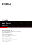
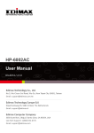
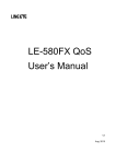
1
Copyright Copyright Edimax Technology Co., Ltd. all rights reserved. No part of this publication may be reproduced, transmitted, transcribed, stored in a retrieval system, or translated into any language or computer language, in any form or by any means, electronic, mechanical, magnetic, optical, chemical, manual or otherwise, without the prior written permission from Edimax Technology Co., Ltd. Edimax Technology Co., Ltd. makes no representations or warranties, either expressed or implied, with respect to the contents hereof and specifically disclaims any warranties, merchantability, or fitness for any particular purpose. Any software described in this manual is sold or licensed as is. Should the programs prove defective following their purchase, the buyer (and not this company, its distributor, or its dealer) assumes the entire cost of all necessary servicing, repair, and any incidental or consequential damages resulting from any defect in the software. Edimax Technology Co., Ltd. reserves the right to revise this publication and to make changes from time to time in the contents hereof without the obligation to notify any person of such revision or changes. The product you have purchased and the setup screen may appear slightly different from those shown in this QIG. For more information about this product, please refer to the user manual on the CD-ROM. The software and specifications are subject to change without notice. Please visit our website www.edimax.com for updates. All brand and product names mentioned in this manual are trademarks and/or registered trademarks of their respective holders. 1 Contents Chapter 1: Introduction ..................................................................................................................................... 3 1.1 Product Features .................................................................................................................................. 3 1.2 Application ........................................................................................................................................... 3 1.3 Compatibility ........................................................................................................................................ 3 1.4 System Requirements .......................................................................................................................... 4 Chapter 2: Adapter ............................................................................................................................................ 5 2.1 Ethernet Port........................................................................................................................................ 5 2.2 Buttons ................................................................................................................................................. 5 2.3 LEDs ...................................................................................................................................................... 6 Chapter 3: Utility Software Installation ............................................................................................................. 7 Chapter 4: Using the Utility Software .............................................................................................................. 14 4.1 Main Tab ............................................................................................................................................ 14 4.2 Privacy Tab ......................................................................................................................................... 15 4.3 Diagnostics Tab .................................................................................................................................. 16 4.4 About Tab ........................................................................................................................................... 17 Chapter 5: Security (Group) Button ................................................................................................................. 18 5.1 Forming a HomePlug AV Logical Network ......................................................................................... 18 5.2 Joining a Network .............................................................................................................................. 18 5.3 Leaving a Network ............................................................................................................................. 19 2 Chapter 1: Introduction 1.1 Product Features Data rates up to 500Mbps Transmits network data via existing electrical wires (no external cabling required) Easy plug-and-play setup Works with routers, computers, and other network devices Consumes less than 1W of power in power saving mode 1.2 Application High-definition (HD) and standard-definition (SD) video distribution Broadband Internet sharing Internet Protocol Television (IPTV) and Voice over Internet Protocol (VoIP) applications 1.3 Compatibility 200Mbps and 500Mbps powerline devices (HomePlug AV standard) are incompatible and cannot be used with 14Mbps and 85Mbps powerline devices (HomePlug 1.0 and 1.1 standards). 3 1.4 System Requirements Operating System CPU RAM Free Disk Space Network Interface Utility can support Windows 2000/XP/Vista/7 Intel Pentium III 2.0GHz (or higher) 128MB (at least) 20MB (at least) Fast Ethernet (100Mbps) network interface and an Ethernet cable 4 Chapter 2: Adapter 2.1 Ethernet Port You can connect the HP-5001 to a router, a computer, or any network device via this Ethernet port. 2.2 Buttons Reset Security (Group) Press and hold the reset button for 3 seconds to restore the powerline adapter to factory defaults. Press and hold the “Security (Group)” button for more than 10 seconds to randomize the adapter’s NMK value; or press and hold the “Security (Group)” button for 3 seconds to add the powerline adapter to the existing AV logical network (AVLN). 5 2.3 LEDs On Ethernet Port Green Ethernet connection established Flashing Network activity Off No Ethernet connection On Power PLC Powered on In power saving mode Green Flashing Device resetting Synchronizing password Off Powered off Green: PHY RATE > 80Mbps Green/ On Orange: 40Mbps < PHY RATE < 80Mbps Orange/ Red: PHY RATE < 40Mbps Red Off Not in a powerline network 6 Chapter 3: Utility Software Installation Step 1 Before installing the utility software, make sure that no other powerline utility is installed on your computer. If any other utility software is installed, uninstall it and reboot the computer. Step 2 Insert the CD into your CD-ROM drive. When the following image appears, click “500Mbps Device”. Step 3 Then click “Setup Utility”. 7 Note : You will get the following image, if your computer did not install WinPcap4.1.2 before. Please click “Apply” to install WinPcap4.1.2. 8 9 10 Step 4 When the setup wizard appears, click “Next” to continue. Step 5 Select where you want to install the utility software, and then click “Next”. 11 12 Step 6 After the installation is complete, click “Close”. Step 7 An icon will appear on your desktop. Click the icon to open the utility software. Note: You can manage all the connected powerline adapters with the utility software. However, installing the utility software is optional. 13 Chapter 4: Using the Utility Software 4.1 Main Tab The “Main” tab provides a list of powerline adapters connected to the computer. The upper panel displays local powerline adapters. The lower panel displays remote powerline adapters in the network. Connect Rename Enter Password Add Scan Click “Connect” and the utility software will scan for other local powerline adapters. Select a device and click “Rename” to rename the device. By default, this column is blank. Select a device and click “Enter Password” to set up a password for the device. This button is used to add a remote powerline adapter to the existing network. Click “Scan” and the utility software will perform an immediate scan of other remote powerline adapters. By default, the utility automatically scans every few seconds. 14 4.2 Privacy Tab In the “Privacy” tab, you can create a private network by changing the default network name and configure its security settings. If the network name is modified to anything other than the default, the network type in the “Main” tab will be changed to “Private”. Set Local Device Only Set All Devices This button is used to change the network name and password of the local device. This button is used to change the logical network of all devices that appear in the “Main” tab. 15 4.3 Diagnostics Tab The “Diagnostics” tab displays the system information and history of all remote devices. The upper panel displays technical data concerning the software and hardware on the host computer and the lower panel displays the history of all remote devices. 16 4.4 About Tab The “About” tab contains some basic information about the software. You can also enable or disable the autoscan function under “Preferences”. 17 Chapter 5: Security Button This section demonstrates how to add or remove devices from a HomePlug AVLN with the “Security (Group)” button. The “Power” LED indicates the operation status and result. 5.1 Forming a HomePlug AV Logical Network When two devices with different NMK values are connected to the same powerline and you want them to form a logical network, follow the following procedures: Step 1 Press the “Security (Group)” button on device A for less than 3 seconds. Step 2 Press the “Security (Group)” button on device B for less than 3 seconds. This should be done within 1 minute. Step 3 Wait for the connection to complete. The “Power” LED on both devices will blink evenly at 1-second intervals until the operation succeeds or fails. If the connection succeeds, it will illuminate steadily. If an error occurs, the power LED on the adder will blink unevenly until the “Security” button on the adder is pressed again or the joiner is reset. A PLC B PLC C PLC A and B are not part of AVLN A and B want to form an AVLN Press NMK button on A less than 3 sec. Press NMK button on B less than 3 sec. A becomes “joiner” B becomes “joiner” B determines that A MAC address < B MAC address B becomes “adder” A accepts NMK from B 5.2 Joining a Network If you want to add a new device to an existing network, follow the following procedures: Step 1 Press the “Security” button on the new device for at least 3 seconds. 18 Step 2 Press the “Security” button on any device in the network for less than 3 seconds. This should be done within 1 minute. Step 3 Wait for the connection to complete. The “Power” LED on both devices will blink evenly at 1-second intervals until the operation succeeds or fails. If the connection succeeds, it will illuminate steadily. If an error occurs, the power LED on the adder will blink unevenly until the “Security” button on the adder is pressed again or the joiner is reset. A PLC B PLC C PLC A and B form an AVLN C wants to join the AVLN Press NMK button on B less than 3 sec. Press NMK button on C less than 3 sec. B becomes “adder” C becomes “joiner” C accepts NMK from B 5.3 Leaving a Network If you want to remove a device from an existing network, follow the following procedures: Step 1 Press the “Security” button on the device to be removed for at least 10 seconds. Step 2 Wait for the device to reset. The “Power” LED on the device to be removed will momentarily extinguish. It will start to blink after it has restarted. Then it will illuminate steadily if no error occurs. You can then disconnect the device. A PLC B PLC C PLC A, B and C form an AVLN A wants to leave the AVLN Press NMK button on A more than 10 sec. A computes random NMK A resets and restarts 19 Federal Communication Commission Interference Statement This equipment has been tested and found to comply with the limits for a Class B digital device, pursuant to Part 15 of FCC Rules. These limits are designed to provide reasonable protection against harmful interference in a residential installation. This equipment generates, uses, and can radiate radio frequency energy and, if not installed and used in accordance with the instructions, may cause harmful interference to radio communications. However, there is no guarantee that interference will not occur in a particular installation. If this equipment does cause harmful interference to radio or television reception, which can be determined by turning the equipment off and on, the user is encouraged to try to correct the interference by one or more of the following measures: 1. Reorient or relocate the receiving antenna. 2. Increase the separation between the equipment and receiver. 3. Connect the equipment into an outlet on a circuit different from that to which the receiver is connected. 4. Consult the dealer or an experienced radio technician for help. FCC Caution This device and its antenna must not be co-located or operating in conjunction with any other antenna or transmitter. This device complies with Part 15 of the FCC Rules. Operation is subject to the following two conditions: (1) this device may not cause harmful interference, and (2) this device must accept any interference received, including interference that may cause undesired operation. Any changes or modifications not expressly approved by the party responsible for compliance could void the authority to operate equipment. Federal Communications Commission (FCC) Radiation Exposure Statement This equipment complies with FCC radiation exposure set forth for an uncontrolled environment. In order to avoid the possibility of exceeding the FCC radio frequency exposure limits, human proximity to the antenna shall not be less than 2.5cm (1 inch) during normal operation. Federal Communications Commission (FCC) RF Exposure Requirements SAR compliance has been established in the laptop computer(s) configurations with PCMCIA slot on the side near the center, as tested in the application for certification, and can be used in laptop computer(s) with substantially similar physical dimensions, construction, and electrical and RF characteristics. Use in other devices such as PDAs or lap pads is not authorized. This transmitter is restricted for use with the specific antenna tested in the application for certification. The antenna(s) used for this transmitter must not be co-located or operating in conjunction with any other antenna or transmitter. R&TTE Compliance Statement This equipment complies with all the requirements of DIRECTIVE 1999/5/EC OF THE EUROPEAN PARLIAMENT AND THE COUNCIL of March 9, 1999 on radio equipment and telecommunication terminal equipment and the mutual recognition of their conformity (R&TTE). The R&TTE Directive repeals and replaces in the directive 98/13/EEC (Telecommunications Terminal Equipment and Satellite Earth Station Equipment) As of April 8, 2000. Safety This equipment is designed with the utmost care for the safety of those who install and use it. However, special attention must be paid to the dangers of electric shock and static electricity when working with electrical equipment. All guidelines of this and of the computer manufacture must therefore be allowed at all times to ensure the safe use of the equipment. EU Countries Intended for Use The ETSI version of this device is intended for home and office use in Austria, Belgium, Bulgaria, Cyprus, Czech, Denmark, Estonia, Finland, France, Germany, Greece, Hungary, Ireland, Italy, Latvia, Lithuania, Luxembourg, Malta, Netherlands, Poland, Portugal, Romania, Slovakia, Slovenia, Spain, Sweden, Turkey, and United Kingdom. The ETSI version of this device is also authorized for use in EFTA member states: Iceland, Liechtenstein, Norway, and Switzerland. EU Countries Not Intended for Use None 20 21