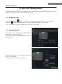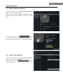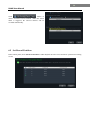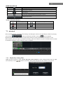
1
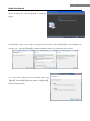
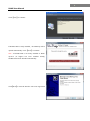
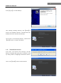
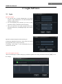
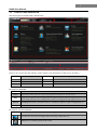
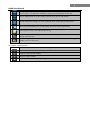
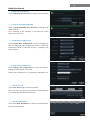
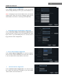
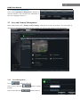
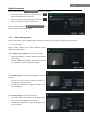
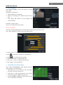
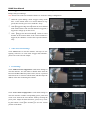
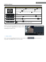
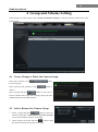
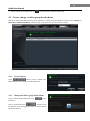
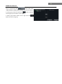
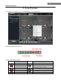
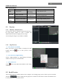
NVMS User Manual Version 1.0.0 2012-11-28 Contents 1 2 3 4 5 6 7 8 Software Introduction ........................................................................................................................................ 1 1.1 Summary ................................................................................................................................................ 1 1.2 Operation Environment ......................................................................................................................... 1 1.3 Install and Uninstall ............................................................................................................................... 2 1.3.1 Install the Software .................................................................................................................... 2 1.3.2 Uninstall the Software ............................................................................................................... 5 Login Software .................................................................................................................................................. 6 2.1 Login ...................................................................................................................................................... 6 2.2 Control Panel Instruction ....................................................................................................................... 7 Device Management .......................................................................................................................................... 9 3.1 Add Device ............................................................................................................................................ 9 3.2 View, Change or Delete Device ........................................................................................................... 10 3.3 Area and Camera Management............................................................................................................ 13 3.3.1 Area Management .................................................................................................................... 13 3.3.2 Camera Management ............................................................................................................... 14 Group and Scheme Setting .............................................................................................................................. 18 4.1 Create, Change or Delete the Camera Group....................................................................................... 18 4.2 Add or Remove the Camera Group ..................................................................................................... 18 4.3 Create, change or delete group dwell scheme ...................................................................................... 19 4.3.1 Create Scheme ......................................................................................................................... 19 4.3.2 Change and delete group dwell scheme ................................................................................... 19 Live Preview .................................................................................................................................................... 21 5.1 Preview ................................................................................................................................................ 22 5.1.1 Monitory Point Preview ........................................................................................................... 22 5.1.2 Stop Preview ............................................................................................................................ 22 5.2 Dwell Preview ..................................................................................................................................... 22 5.2.1 Group Dwell Preview .............................................................................................................. 23 5.2.2 Scheme Dwell Preview ............................................................................................................ 23 5.3 Preview Control ................................................................................................................................... 23 5.4 Snap ..................................................................................................................................................... 24 5.4.1 Snap ......................................................................................................................................... 24 5.4.2 Snap Number ........................................................................................................................... 24 5.4.3 Record and Snap Path .............................................................................................................. 25 5.5 Multi-screen to Preview ....................................................................................................................... 25 5.6 Talk and Broadcast............................................................................................................................... 25 5.6.1 Talk .......................................................................................................................................... 25 5.6.2 Broadcast ................................................................................................................................. 26 5.7 PTZ Control ......................................................................................................................................... 26 5.7.1 Parameter Configuration of PTZ ............................................................................................. 26 5.7.2 PTZ control .............................................................................................................................. 26 Record Management ........................................................................................................................................ 27 6.1 Manual Record..................................................................................................................................... 27 6.2 Schedule Record .................................................................................................................................. 27 6.3 Motion Detection Record..................................................................................................................... 28 6.4 Sensor Alarm Record ........................................................................................................................... 28 6.5 Set Record Partition ............................................................................................................................. 29 Playback Management ..................................................................................................................................... 30 7.1 playback ............................................................................................................................................... 31 7.1.1 Playback by Setting Time ........................................................................................................ 31 7.1.2 Playback by Searching Event................................................................................................... 32 7.2 Snap When Playback ........................................................................................................................... 32 7.3 Clip and Backup Record ...................................................................................................................... 32 7.3.1 Clip and Backup Record .......................................................................................................... 32 7.3.2 Backup Path Configuration ...................................................................................................... 32 Alarm Management ......................................................................................................................................... 33 8.1 Sensor Alarm ....................................................................................................................................... 33 8.2 Motion Detection Alarm ...................................................................................................................... 34 Video Loss Alarm ................................................................................................................................ 35 Alarm Preview ..................................................................................................................................... 35 8.4.1 Alarm Preview Configuration .................................................................................................. 35 8.4.2 Alarm Preview ......................................................................................................................... 36 9 E-Map .............................................................................................................................................................. 37 9.1 Create map ........................................................................................................................................... 37 9.2 Modify or Delete Map, Hotspot and Hotzone ..................................................................................... 37 9.2.1 Change or Delete Map ............................................................................................................. 38 9.2.2 Add, Change and Delete Hotzone ............................................................................................ 38 9.2.3 Add, Change and Delete Hotspot............................................................................................. 39 9.3 E-map Monitoring Settings.................................................................................................................. 39 9.4 E-map live preview .............................................................................................................................. 39 10 Local Log ......................................................................................................................................................... 42 10.1 Search log ............................................................................................................................................ 42 10.2 Log Maintenace ................................................................................................................................... 42 10.3 Export .................................................................................................................................................. 42 11 User Management ............................................................................................................................................ 43 11.1 Create a Resource with the Default Permission ................................................................................... 43 11.2 Create, change and delete users ........................................................................................................... 43 11.3 Account Right Configuration............................................................................................................... 44 12 Basic ................................................................................................................................................................ 46 12.1 System Startup and Maintenance ......................................................................................................... 46 12.2 Backup and Restore ............................................................................................................................. 46 12.2.1 Backup System Configuration data ......................................................................................... 47 12.2.2 Restore System Configuration Data......................................................................................... 47 12.3 Manually Trigger the Alarm Output .................................................................................................... 47 8.3 8.4 1 NVMS User Manual 1 Software Introduction In this chapter, you will read a detailed introduction of the operation environment, install & uninstall of this software. 1.1 Summary Network Video Monitoring System (hereinafter referred to as ―NVMS‖) is a monitoring client which is specially designed for network video surveillance. After the network video monitoring system is well built, the super administrator can control the video input signal devices, such as cameras, domes, etc., to achieve live monitor, video record and backup by configuring the video parameters and viewing the live in the control panel. Users can choose the menu to control video surveillance system in the control panel. The main functions of the control panel include live view, playback, E-map, device management, group and scheme settings, user account and permission, local log, basic configuration and alarm management. 1.2 Operation Environment 1)Operating System Requirement: System Windows XP Windows 7 Recommendation Windows XP professional version (32bit), direct 9.0c. Microsoft YaHei front need to be installed. Windows 7 (32bit,support SP1),Direct 11.0 or higher 2)Hardware Requirement: Item Recommendation CPU Intel Core Dou,2.6GHz or higher Memory 2GB or above HDD 250GB or above Graphics Card Independent graphics card; 512M graphics memory or higher 3)When running NVMS-1000, you need to ensure that all the running antivirus software and firewall are closed, so that the program of the NVMS can be installed. 2 NVMS User Manual 1.3 Install and Uninstall 1.3.1 Install the Software Double click ―Setup.exe‖ to enter the Installation Wizard Click【Next】to install. Select ―I accept the terms of license agreement‖ and click 【Next】to continue. Click 【Browse】 button to change the directory to save the program files. Click【Next】to continue. 3 NVMS User Manual Check ―Vcredist_x86‖ and click【Next】to install this plug-in. Click【Next】; check ―I have read and accept the license terms‖ and click【Install】to start installation of Vcredist_x86; then click【Finish】to complete installation. Please refer to the below three pictures. Note: If the above plug-in has been installed, please click 【Repair】 and click【Next】to repair software. Click【Finish】 button to finish repairing. 4 NVMS User Manual Click【Next】to continue. If NVMS-1000 is firstly installed,the WinPcap will be opened automatically. Click【Next】to continue Note:If NVMS-1000 is not firstly installed or WinPcap4.0.2 (or higher) has been installed already, NVMS-1000 will be installed automatically. Click【Next】to enter the interface of License Agreement 5 NVMS User Manual Click【I Agree】to install WinPcap After finishing installing WinPcap, click【Finish】to return to the installation interface of NVMS-1000. The NVMS-1000 will be installed automatically. At last, check ―Create desktop shortcuts‖, and then click 【Finish】button to complete installation. 1.3.2 Uninstall the Software Click ―Start‖ at the bottom of the desktop to find the shortcut of NVMS-1000 ; then click ―Uninstall‖ to pop up a dialog window; click【Yes】to uninstall the software. At last, click【Finish】button to finish uninstall . 6 NVMS User Manual 2 Login Software 2.1 Login First time to login: ① For the first time to run the NVMS-1000, you need to register a super administrator. You shall self-define the username and password. ② To avoid forgetting the password, you can set some questions to help you find the password quickly. ③ After you input your user name, password and set the questions and answers, click【Register】to enter into the software. Input the username and password created by you. If checking ―Remember Password‖, there will be no need to input password when you log in next time. If checking ―Auto Login‖, it will automatically log in as current user next time. Successful login for first time: After successful login, a window will pop up. Check the partition for storing record files and click【OK】to save the settings. 7 NVMS User Manual 2.2 Control Panel Instruction The control panel of NVMS-1000 is shown below There are five areas in the main interface of this software. The descriptions of each area are as follows: Area Description Area Description 1 Function Area 2 Tab Bar—to display the operated functions 3 Menu Bar 4 Alarm Information List. 5 Status information list Description of Menu Bar Menu Description Start Export the control panel, live preview, playback tab and lock or exit the client. View Export the live preview, control panel, local log, E-map, alarm preview, playback, user account and permission, basic configuration and device management and organize the live view System Help Including lock client,broadcast to device, switch user, import or export configuration, etc. View user manual and software version Descriptions of Function Module Menu Description Live Preview: To view live images and record, snap, control PTZ, etc. Playback: To remotely play the local record. 8 NVMS User Manual E-map: To manage and display maps, hot zones and hotspots. To operate E-maps – zoom in/out e-maps, view hot zones and hotspots, display alarm information on the map. Device Management: To create, modify or delete areas, devices and cameras. Group and Scheme Settings: To create, modify or delete camera groups and schemes. User Account and Permission: To add, modify, delete user and user permission. Local Log: To search, view and backup local log. Basic Configuration: To setup record partition and path, system startup and maintenance & backup and restoration. Alarm Management: To add or remove the sensor of the area; To setup alarm trigger and modify the area of the sensor. Descriptions of Other Buttons Button Description Click to hide the window Click to zoom in/out the window Click to exit the window Click to extend or shrink the window (eg. Extend or shrink the list of alarm information list) 9 NVMS User Manual 3 Device Management In the control panel, click icon to enter the device management interface. 3.1 Add Device Click button to enter the interface. ① Select device type and input device name; ② Input IP address or domain, port of the device, then input its user name and password. ③ Create an area. If you haven’t created area, you can click ―Create a New Area‖ to create. ④ Check ―Upload bandwidth more than 2M‖ according to the actual network situation. Checking or not checking it will affect the stream choice of live preview. Note: You can click ―Create an Area‖ shortcut menu under Device to create an area in the control panel. 10 NVMS User Manual Add Online Devices Click button to automatically search online devices in the local network. Click a device to display its basic information. Double click it to add it. 3.2 View, Change or Delete Device Select the added device and click device from the list. button to delete the Select the added device and click to pop up a window. In this interface, you can change the device name, address, port, etc. or change basic configuration, time configuration, etc. Change the Device Name Click “Change Device Name” to change the name of selected device. Change Device Address Click “Change Device Address” to change the IP address of selected device. Change Deviec Port Number Click “Change the Port Number of Device” to change the port of selected device. Change Device User Name Click “Change Device User Name” to change the device account name. 11 NVMS User Manual Change Device Password Click “Change Device Password” to change device password. Change Connection Bandwidth Check “Upload bandwidth more than 2M” according to the actual situation. Note: Checking or not checking it will affect the stream choice of live preview. Change Basic Configuration Click “Change Basic Configuration” to pop up a dialog box. You can change the basic configuration of device and check ―Permission Check‖ or ―Record Coverage‖ according to the actual situation. Change Time Configuration Click “Change Time Configuration” to enter the interface. Change the time and date if you need. Check ―Sync by NTP Server‖ to synchronize with NTP server. View Device Log Click “View Device Log” to enter the interface. Choose the type of system logs; enter start time and enter time to search the log information of the device. View Disk Information Click “View Disk Information” to check the detail information of disk from the list. 12 NVMS User Manual Change Network Configuration Click “Change Network Configuration” to enter the interface. You can change HTTP port, Server port; network address, etc. Note: If changing the port and IP address there, the network will disconnect. Then you need to accordingly change the port and IP address of the device connecting the NVMS-1000. Alarm Input Trigger and Schedule Configuration Click “Alarm Input Trigger and Schedule Configuration” to enter the interface. Select a sensor corresponding to the alarm input; choose a type and holding time for it. You also can set trigger alarm or other configurations. Device Alarm Output Configuration Click “Alarm Output Configuration” to enter the interface. Select an alarm output and holding time; then edit a name for it. You can enable buzzer alarm and set a time for it. Abnormal Alarm Configuration Click “Abnormal Alarm Configuration” in to enter the interface. Choose the alarm type according to your need. Enable ―Buzzer Alarm‖ and select alarm out. 13 NVMS User Manual User Information Management Click “User Information Management” shortcut to enter the interface. You can check the information of user who is logging in the device. 3.3 Area and Camera Management In the control panel, click ―Change Camera Settings‖ under Device to enter the interface. You can modify or delete the area and manage the cameras. Select a camera you want to setup as shown on the below figure. 3.3.1 Click Area Management button to create area. Select an area and click its name. Select an area and click button to change button to delete it. 14 NVMS User Manual Select an area and click to pop up a window. ① Check the camera on the left column and click button to add the camera to the area. ② Check the camera on the right column and click button to remove the camera from the area. Select a camera and click ton to modify the area of this camera. 3.3.2 but- Camera Management The real-time image will be displayed after selecting a camera. You can setup the parameters of this camera. Image Settings Image settings include image video parameter, image quality and image display. Click “Image video parameters” to enter the interface . ① Adjust the brightness, contrast, saturation and chroma of the image. ② Clicking 【Restore Default】 button will restore the above parameters to factory default settings. Click “Image Quality” under Image Settings to enter the interface. ① Choose the device stream, resolution, quality, etc. according to practical situation. ② Click【Copy to】button to apply the setting to the selected channel. Click “Image Display” to enter the interface. ① Create the camera’s name and set up its display position on the OSD including the time stamp. ② Click【Copy to】button to apply the settings to the selected channel. 15 NVMS User Manual Record Settings Click “Record Settings” to enter the interface as shown on the right. Under the record of device ① Enable schedule or record audio ② Choose pre-recording time, duration and record save time. ③ Click 【Copy to】 button to save the settings to the selected channel. Under the record of system You can set schedule and record stream. How to set schedule? The steps of setting schedule between record of device and record of system are same. Click 【Set Schedule】 button to pop up the follow figure. Check ―7x24‖ or ―Custom Schedule‖ to set schedule. Click icon and move the cursor to select the time. Click icon to delete the selected time. Clicking ―Manually‖ to manually input time Click ―All‖ / ―reverse‖ to quickly select the time. Click ―Empty‖ to clear all the time. Motion Detection Alarm Settings Click “Area and Sensitivity” under Motion Detection Alarm Setting to enter the interface. ① Drag slide bar to set the sensitivity value. The higher the value is, the more sensitive it is. ② Click ―Erase‖/ ―Add‖, then hold press ―Ctrl‖ and left click mouse to delete /add the area you want. ③ Click 【All】【 / Reverse】【 / Clear All】 button to select area or clear all the area quickly. 16 NVMS User Manual Click “Trigger and Schedule” under Motion Detection Alarm Setting to enter the interface which includes device linkage and system linkage. Note: Please refer to the user manual of the device for device linkage configuration. ① Under the system linkage, check ―Trigger to Play Audio File‖. If the motion alarm of a certain channel is triggered, there will be given out a sound like ―beep‖. ② Click 【Trigger the Big Screen】 button to select channel. If the motion alarm of the selected channel is triggered, a big picture will pop up on the screen. ③ Click 【Trigger the Record Channel】 button to select channel. If the motion alarm of the selected channel is triggered, the channel’s record will be opened automatically. Video Loss Alarm Settings Click “Video Loss” to enter the interface. The steps of configuring video loss are same with ―Trigger and Schedule‖, please refer to the relevant chapter. PTZ Settings Click “PTZ Protocol Configuration” under PTZ Settings to enter the interface. You can enable or disable PTZ. From the Protocol and Baud Rate drop-down menu, choose a protocol and a baud rate to associate with the PTZ, and then input the address of the PTZ connecting the software. Click “Preset Point Configuration” under PTZ Settings to enter the interface. Enable corresponding preset points and create a new name in the ―New Name‖ field by selecting the preset point. Adjust the dome direction, speed, etc by clicking the buttons. Click【Save Position】to save the current position of the dome. 17 NVMS User Manual The definitions of the buttons are below: Buttons Description means the dome rotate up; dome rotate up right; rotate left down; rotate left; means the dome rotate up left; means the means the dome rotate down. means the dome means the dome rotate right down; means the dome means the dome rotate right; means the dome stop ro- tating Drag the slider bar to adjust rotation speed of the dome Focus button. Click tain short focus button to obtain long focus. Click button to ob- Iris button. Click button to increase light of the dome. Click to decrease light of the dome Zoom button. Click button button to zoom in the picture of this camera. click button to zoom out the picture of this camera Return to Area and Camera Management interface, and then click “Cruise Line Configuration” PTZ Settings. You can add/change/preview/delete curies. Remove camera In the Area and Camera Management interface, select a camera, click alog window, click【OK】button to remove the camera. button to pop up a di- 18 NVMS User Manual 4 Group and Scheme Setting In the interface of control panel, click “Group and Scheme Setting” to enter the interface. Please refer to the below picture: 4.1 Create, Change or Delete the Camera Group In the above interface, click to create a group. Select a group in the group list, click delete it. button button to Select a group and click button to enter the interface as shown on the right. You can change the group name and dwell time interval in this interface. 4.2 Add or Remove the Camera Group ① Select a group and click button to enter the interface. Then click “Add or Remove the Camera Group” to pop up the window as shown on the right. ② Check cameras on the left and click button to add the selected cameras to the group on the right. 19 NVMS User Manual ③ Check cameras on the right, then click button to remove them from the group. 4.3 Create, change or delete group dwell scheme Scheme is used for dwelling group by group. Therefore, at least one group should be created. Click “Change or Delete the Group Dwell Scheme” on the left side of the menu to enter the interface as below. 4.3.1 Create Scheme Click button to create a scheme. The added scheme will be displayed in the scheme list. 4.3.2 Change and delete group dwell scheme Select a scheme in the scheme list, click to delete it. button Select a scheme and click button to enter the interface. You can change the name of scheme and the dwell time interval. 20 NVMS User Manual Select a scheme and click button. Then click “Add or Remove Group of the Scheme” to enter the interface. Check group on the left and click selected group to the scheme on the right. button to add the Check group under scheme on the right and click button to remove the group. 21 NVMS User Manual 5 Live Preview In the interface of control panel, click “Live Preview” to enter the interface: Buttons description of live preview: Toolbar on the display window: Icon Description Icon Description Close image Snap Start/stop manual record PTZ control. Clicking the icon will display the control panel of PTZ. Start/stop talk Camera configuration Open/close audio Zoon in Fit to window 22 NVMS User Manual Right button funtions: Menu Description Menu Description Snap Snap picture Open Manual Recording Start manual record Start talk Start or stop talk Camera Configuration Enter the interface of the area and Camera configuration Stream Choose stream to view. PTZ Control To display the control panel of PTZ Enable Audio Enable or close audio Close Preview Close single channel preview Full Screen To display in full screen 5.1 Preview 5.1.1 Monitory Point Preview To start the live preview, drag the cameras from the list to the right display window or select a window and double-click the camera to display the live image. You can drag the image to any window at random. 5.1.2 Stop Preview Close Preview of Channel Place your mouse on the window to display the menu toolbar, then click channel. icon to close preview of this Close Preview by Right-clicking Choose “Close Preview” by right-clicking the display window to close preview of this channel. Close All Preview Click windows. icon on the main menu toolbar to close all the 5.2 Dwell Preview After setting up group or scheme (Please refer to chapter 4 for creating group), enter to the live preview interface and click button to display the the group list or scheme list. The below sections will introduce how to realize group dwell and scheme dwell. 23 NVMS User Manual 5.2.1 Group Dwell Preview Start Group Dwell In the interface of live preview, click shortcut on the left side to display the groups , drag a group under scheme to any window( icon stands for group). The cameras of this group will play one by one on this window at the set time. Stop Group Dwell Right click the display window to select ―Close Preview‖ to close preview of the this channel or click icon on the main menu bar to close all windows for stopping dwell. 5.2.2 Scheme Dwell Preview Start Scheme Dwell In the interface of live preview, click shortcut on the left side and then drag a scheme to the right window to dwell ( icon stands for scheme).The screen mode will be distributed automatically according to the the number of camera under the group Note:To achieve dwell between devices, the device should be as a unit when adding groups. Then add all the groups into one scheme to dwell. Stop Scheme Dwell Click icon to close all the windows for stoping scheme dwell. 5.3 Preview Control Full Screen Click icon on the display window or right-click to choose ―Full Screen‖ to view in full screen. Right-click to choose ―Exit Full Screen‖ to exit full screen preview. Single Channel in Full Screen Double click the selected window to view in full screen. Double click again to recover the window. Stream of Live Preview Right click on the display window to choose recording stream as shown on the right. The above stream is main 24 NVMS User Manual stream (eg: D1 25fps) and the below is sub stream(eg: CIF 6fps). Modify Device Stream: Click button on the display window to enter the Area and Camera Management interface. Click “Image Quality” under Image Setting to modify device stream. Please refer to chapter 3.3.2 Image Settings for details. Audio Right click on the displaying window to choose ―Enable Audio‖ or click icon to enable audio of this channel. Note: Only one audio can be enabled at the same time. If enabling another channel’s audio, the enabled audio will be closed automatically. Zoom In Click icon on the toolbar in the displaying window to zoom in the image; click icon to recover the image. 5.4 Snap 5.4.1 Snap click button on the toolbar of the selected channel or right click to choose “Snap” to capture the pictures. After snapping pictures, a message prompt box will pop up to remind you the pictures are captured successfully and where the pictures are stored . Note: Capturing pictures can be realized only in live preview or playback. 5.4.2 Snap Number In the interface of control panel, click “Set Snap Default Number” under Basic to configure the number you want to capture every time . 25 NVMS User Manual 5.4.3 Record and Snap Path In the control panel , click “Basic” to enter the interface. Click “Partition and Path” to select a folder to save the record files. Click “Set the Default Path of Snap” under Partition and Path to set up the path to save the snap files. 5.5 Multi-screen to Preview In the interface of live preview, click button to plus a tab of live preview. Drag any tab of live preview or right click the tab of live preview to select ―Float‖ to pop up a independent live preview interface as below. Mulit-screen to display can be realized by draging the independent interface to other screen (graphics card should support mulit-screen output at the same time). Clicking the button of the live preview interface to choose ―Tab view‖ can embed this tab in main interface .。 Note:1. 20 live preview tabs can be added. 2. Live preview interface can be displayed on mulituple screens. 5.6 Talk and Broadcast 5.6.1 Talk Click button on display window or right click to pop up a menu bar. Choose ―Start Talk‖ to enable bidirectional audio. Note: Since NVMS-1000 only allow to open one device’s talk at the same time, the system will stop talk with the current device for enabling new talk with another device which is lauching talk. 26 NVMS User Manual 5.6.2 Broadcast ① Click “System” on the menu bar of software at the upper right ; choose “Broadcast” to enter the interface. ② Click button to pop up a window; then check the devices you want to broadcast, click 【OK】button to save the setting. ③ Click broadcast. button to stop 5.7 PTZ Control 5.7.1 Parameter Configuration of PTZ Please confirm the parameter of PTZ has been configured correctly before operating PTZ. Click icon in display window or “Change Camera Setting” under “Device” to enter the interface. Click “PTZ Setting” to enable PTZ and setup protocol, baud rate and address of PTZ. Note: Here the protocol, baud rate and address of PTZ must be consistent with the PTZ decorder. 5.7.2 PTZ control Return to the live preview interface after configuring parameter of PTZ; select the channel and click icon or right click to choose “PTZ Control” to open the control panel of PTZ. Click the direction buttons to control its rotational direction; drag the slider to control its speed. Click and buttons to adjust focus, iris and zoom. Select a preset point and click point to operate it. to operate this preset point or double click the preset Click【Cruise】button to list the cruises. Select a cruise and click click button to stop cruising. button to cruise; 27 NVMS User Manual 6 Record Management NVMS-1000 supports manual record, schedule record, motion detection record and sensor alarm record. This chapter will introduce the above four record types respectively. 6.1 Manual Record Select a channl and click Then click button or right click to choose ―Open Manual Recording‖ to start recording. button or right click to choose ―Close the Manual Recording‖ to stop recording. Note:If a channel is recording, closing preview will give rise to stopping it 6.2 Schedule Record In the control panel, click “Change Camera Settings” under Device to enter the interface. Select a camera and click “Record Settings” as shown on the right figure. Under record of system , you can choose record stream and set record schedule. Note: Please refer to section 3.2.2 for details. 28 NVMS User Manual 6.3 Motion Detection Record In the control panel, click “Change Camera Settings” under Device to enter the interface. Select a camera and click “Trigger and Schedule” under Motion Detection Alarm Settings as shown on the right figure. Under system linkage, click button to select channel. The selected channel whose motion detection alarm is triggered will be recorded automatically. 6.4 Sensor Alarm Record In the control panel, click “Change Camera Settings” under Device to enter the interface. Select a sensor and click shown on the right. button as 29 NVMS User Manual Click button to choose associated record cameras. When the sensor alarm is triggered, the selected cameras will be recorded automatically. 6.5 Set Record Partition In the control panel, click “Set Record Partition” under Playback as below. You can choose a partition for storing record. 30 NVMS User Manual 7 Playback Management In the interface of control panel, click “Playback” record files. to enter the interface. You can play back the local stored Area Descriptions: Area Description Area Description 1 Playback Area 2 Toolbar 3 Record time Area 4 Resources Area 5 Time search or type search Area Buttons Description of Area 2 Icon Description Screen mode. 1,4,9,16,25 channels are optional Close playback of all channels Full screen Play Pause Stop Playback by single frame. When playback, click then click this button to play frame by frame. button firstly and 31 NVMS User Manual Backup the start time Backup the end time Download Event list. Click this button to pop up the event list Playback speed bar Toolbar on Playback Window: Icon Description Icon Description Close playback Snap Open/close audio Zoom in Fit to window 7.1 playback In the playback interface, select date and record type, then drag the camera to the right display window for playing . you can click button to search the record file , then click button to playback. Playback Record type includes manual record, motion detection record, schedule record, and sensor record. In the timeline, green bar stands for manual record data; yellow bar stands for motion record data; blue bar stands for schedule record data; red bar stands for sensor record data. 7.1.1 Playback by Setting Time Right click the color bar to select “Set the Play Time of the Channel X”, then a dialog window pops up. Input time manually or click button to select time. The system will play the video from the time you set. 32 NVMS User Manual 7.1.2 Click Playback by Searching Event button to display the event list. Double click an event to play this event record. Note: and buttons on the timeline are used to expand and narrow down the time bar, so you can choose a more accurate playback time. What’s more, you may also change playback speed by draging bar. 7.2 Snap When Playback Click button on the playing window to capture pictures. A message prompt will pop up after snapping. 7.3 Clip and Backup Record 7.3.1 Clip and Backup Record When playing back record file, click button to set the start time; click click button to download the video files within the configured time. Note: The default path is C:\\backup. 7.3.2 Backup Path Configuration In the control panel interface, click Basic to enter the interface. Then click “Backup Path Settings” to choose path to save. button to set the end time. then 33 NVMS User Manual 8 Alarm Management 8.1 Sensor Alarm In the control panel, click “Alarm Management” to enter the interface. Add or Remove Sensor of the Area In the interface of Alarm Management, choose an area, click button to enter the interface. ① Check the sensor under the area on the right and click button to move out the sensor . ② Check the sensor on the left and click sensor. button to add Rename or Change Area In the interface of Alarm Management, choose a sensor and click click button to change the area of sensor. button to change its name; 34 NVMS User Manual Alarm Link Setup In the interface of Alarm Management, choose a sensor and click button to enter the interface. If checking “Trigger Alarm Playback”, there will be a sound like ―beep‖ when sensor alarm is triggered. Add Associated Preview Camera Click to pop up a window; check cameras and click【OK】 button to save the setting. When sensor alarm is triggered, the alarm preview and e-map preview will pop up automaticallly. Select the added camera, click remove the camera. to Add Associated Record Camera Click to enter the interface; check the associated cameras and click 【OK】 button to save the setting. When the sensor alarm is triggered, the selected channels will be recorded automatically. Select the added camera, click 8.2 Motion Detection Alarm In the control panel, click “Change Camera Settings” under Device. Select a camera and click “Motion Detection Alarm Setting” to enter the interface as right. You can adjust the detection sensitivity and setup the motion area. to remove the camera 35 NVMS User Manual Click “Trigger and Schedule” to enter the interface as shown on the right. Please refer to section 3.3.2 for details. 8.3 Video Loss Alarm In the control panel, click “Change Camera Settings” under Device. Choose a camera and click “Video Loss Alarm Setting” to enter the interface. Please refer to section 3.3.2 for details. 8.4 Alarm Preview The interface of alarm preview will automatically pop up if the relevant alarm page and alarm preview have been alrealy configured. 8.4.1 Alarm Preview Configuration Motion Detection Alarm: In the ontrol panel, click “Change Camera Settings” under Device to enter the interface. Select a camera, and then click “Trigger and Schedule” shortcut under Motion Detection Alarm Settings to appear a window; click 【Trigger the Big Screen】 button under system linkage to select channel. Video Loss Alarm: Click “Video Loss” to enter the interface; click 【Trigger the Big Screen】button under System Linkage to select channel. Sensor Alarm: In the ontrol panel, click “Alarm Management” to enter the interface. Click button to add the associated preview cameras. 36 NVMS User Manual In the control panel, click ― Change Alarm Preview Settings” under Live Preview to pop up the window ① Alarm preview will pop up automatically when alarm is triggered if checking ―Automatic Pop-up Alarm Page‖. ② Alarm preview will pop up automatically in full screen when alarm if triggered if checking ―Full Screen Display When Popping Up‖. ③ Choose a display monitor from the ―Full Screen Display‖ drop-down menu. The alarm image will display on the designated monitor when alarm is triggered. ④ Choose the number of screen. 8.4.2 Alarm Preview After configuring the alarm, the alarm preview will automatically pop up if the alarm of selected channels is triggered. The default pop-up window of system is independent interface. Please refer to the below figure. Click button on the upper right conner of the sub interface; then select “Tab View” to embed the sub interface in the main interface. 37 NVMS User Manual 9 E-Map In the control panel, click ― E-Map‖ to enter the interface as below: 9.1 Create map In the E-map interface, click 【Shortcuts】 button on the left side to appear the shortcut menu, then click “Create Map File” to enter the interface. Import a map and edit a name for it. 9.2 Modify or Delete Map, Hotspot and Hotzone In the E-map interface, click “Edit E-map” on the left side to enter the interface. 38 NVMS User Manual 9.2.1 Change or Delete Map In the above interface, click “Map File” to appear the map files on the left side. Choose a map and click to change a new name for it. 9.2.2 Add, Change and Delete Hotzone Add Hotzone Click “Map File” and choose a map and then click icon to pop up a dialog widow. ① Check a map related the hotzone ② Click to choose text color displaying under the hotzone icon. ③ Click to choose icons for the hotzones. After finishing, doule clicking a hotzone will lead you to enter this map. Modify and Delete Hotzone Right-click a hotzone on the map. Choose “Modify Hotzone” or “Delelet the Hotzone to change font color, icon or name or delete it. 39 NVMS User Manual 9.2.3 Add, Change and Delete Hotspot In the E-map interface, choose a map, click to enter the interface. ① Check assiciated cameras and sensors ② Click hotspot. ③ Click to choose text color displaying under to choose an icon for the hotspot ④ Edit a name for the hotspot. There is another way to add hotspot. Select a map and double click the camera, or drag the camera to the map for adding hotspot. Note: The hotzones or hotspots will focus on the map in the same position after being added. You should drag them to the corresponding positions on the map. Click to save the settings. 9.3 E-map Monitoring Settings In the E-map interface, click “Monitory Settings of E-map” on the left side to enter the interface. Check ―Automatic Pop-up Alarm Preview Window‖,then click 【OK】 button to save the setting. If the configured hot spots raise the alarm, the preview image will pop up automatically 9.4 E-map live preview In the E-map interface, click “Monitory with E-map” on the left side to enter the interface. Note: If the item ―Edit E-map‖ appears on the below of menu bar in the E-map interface, the current interface is monitory with E-map interface. Double clicking a hotspot will switch to the its map The icon of hotspot will become a flashing light if this hotspot raises the alarm. What’s more, there will be preview windows on the right side if you had checked ―Automatic Pop-up Alarm Preview Window‖. Clicking the alarm preview image will switch to the map whose hotspot issues alarm. 40 NVMS User Manual Area Description: Area Description 1 Menu bar 2 Zoom in/out the map 3 Alarm preview 4 Overall display of map(suppressible) 5 Alarm message prompts Right Click on the Alarm Preview Window: Item Description Item Description Snap Picture capture Open Manual Recording Start manual record Start Talk Start talk PTZ control Click to display PTZ control panel Zoom in Zoom in the image Size of window Recover the image size Stream Choose stream to view Enable audio Enable audio Close preview Stop preview of single channel Click Click respectively . to clear all the number of alarm to make the alarm preview windows to overlap together. You can drag each window to view 41 NVMS User Manual click button to tile the alarm preview windows on the right side. Right click on the map to pop up a menu bar. Choose ―Full Screen‖ to view the image in full screen. Right click on the map to choose ―Exit Full Screen‖ to exit. 42 NVMS User Manual 10 Local Log In the interface of control panel, click “Local Log” to enter the interface. 10.1 Search log Choose main type, sub type , set the start time and end time, click【Inquire】button to search the relvent log information. click【Frst page】 【Previous】 【Next】 【Last page】to view the information on different pages. 10.2 Log Maintenace In the log interface, click button to pop up a dialog window. You can save the information of log for a certain time by configuration in this interface. 10.3 Export In the log interface, click button , then choose a storge path to export the log information. 43 NVMS User Manual 11 User Management In the interface of control panel, click “User Management” to enter the interface. There is only one super user registered by you when firstly log in the system. You can add several users and set right for them through the function of ―Set Account Rright‖. 11.1 Create a Resource with the Default Permission In the above interface, cheaking “Create a Resource with the Default Permission” means that permission of new resources will be given to all the users if you are going to create new resources. 11.2 Create, change and delete users In Create Account the interface of User Management, click to pop up a dialog window. Input account name and password. Choose account type and default right. You can bind account by e-mail or telephone and add description if you wish. Note: Two types of user: administrator and operater. administrator enjoys all the system permissions except account and permission management. Operator only enjoy the permissions of broadcast, searching and exporting log 44 NVMS User Manual If you have checked ―Default Permission‖ under intitial permission when creating new account, all the resouce permissions and system permissions will be added for the user Change Account In the interface of User Management, select a user and click button to enter the interface. You can change account name, password, e-mail address, etc. according to need. Delete Account In the interface of User management, select a user and click button to delete it . 11.3 Account Right Configuration In the interface of User Management, select a user, then click Camera Permission In the interface of Camera Permission, click button to add resouces, check camera permissions on the right. You can add different permissions for different users. to enter the interface. 45 NVMS User Manual Device Pemission Click “Device Permission” to enter the interface. Select the right on the right hand you want to enjoy. E-map Permission Click “E-map Permission” to enter the interface. Add map permission for the selected user. System Permission Click “System Permission” to enter the interface, you can set the right of broadcast , searching log information and exporting it for the user you selected. Restore Default Permission In the interface of account right management, select a user and click permission of this user. to restore default Clear Permission In the interface of account right management, select a user and click permission. to clear this user’s 46 NVMS User Manual 12 Basic In the interface of control panel, click “Basic” to enter the interface. System startup and maintenace, backup and restore will be introduced in this chapter. Partition and Path configuration have been introduced in the above chapter, there we do not repet again. 12.1 System Startup and Maintenance In the interface of Basic Configuration, click ―System Startup and Maintenance” to enter the interface. Under the system startup settings, two ways to enable the software can be select. If checking ―Automaticallly Restart Your Computer‖ , user name and password of the computer need to be input; time interval and restart time need to be selected. 12.2 Backup and Restore When upgrading the software to a new vesion, you should firstly export the data of the previous vesion and then import to the new vesion so that repeated add and settings could be avoided. 47 NVMS User Manual 12.2.1 Backup System Configuration data In the interface of Basic Configuration, click “Backup System Configuration Data” to export the configuration data. 12.2.2 Restore System Configuration Data In the interface of Basic Configuration, click “Restore System Configuration Data” to import the configuration data. 12.3 Manually Trigger the Alarm Output In the control panel, click “Manual Alarm Output” under Basic Configuation to enter the interface. Check ―Enable‖; select a corresponding device and alarm output; then edit a name for it . Then an icon will appear at the right bottom of the software. Clicking this icon will trigger the alarm of selected device.