1
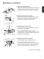
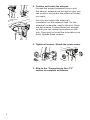
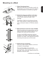
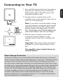
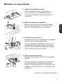
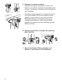
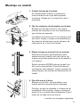
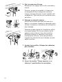
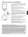
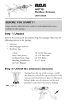
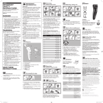
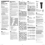
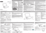
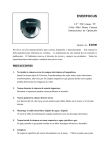
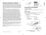
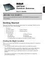
User’s Guide
BEFORE YOU START!!!
Please read the IMPORTANT SAFETY INFORMATION sheet included in
this package.
Getting Started
Remove the antenna and the hardware bag from package. Make sure the
following parts are in the package:
•
•
•
•
Antenna
Amplifier Insert • Power Adapter
Mounting Base • Mounting Arm
Hardware bag:
(2) Screws
(4) Screw Covers
(2) U-Bolts
(2) Clamps
(4) Wing Nuts
(4) Wood Screws
(1) Rubber Boot for Antenna Connector/Coaxial Cable
Finding the Right Location
Before you mount the ANT800, consider the following factors in reception
performance:
• The ANT800 usually performs best when mounted horizontally
• The ANT800 should be mounted on the side of your house that faces
most of your local broadcast towers (See illustration below) Visit
www.antennaweb.org to see the locations of your local broadcast
towers.
• The higher the elevation of the antenna, the better the reception
performance will be.
ENGLISH
ANT800
Outdoor Antenna
Mounting the Antenna
The ANT800 mounting bracket gives you flexibility in mounting the antenna.
The ANT800 can be mounted:
• To a surface, such as a rooftop, eaves, siding, or rafters in
an attic
— OR —
• To a standard mast (not included)
WARNING: Never hang anything from the ANT800; never attach foreign
objects to the ANT800.
NOTES: Do not install the ANT800 on any metal surface, including
aluminum siding. Mounting on a metal surface will seriously degrade
reception quality.
In most cases, the ANT800 provides the best performance when mounted
outdoors in a high location (such as on the roof or high up on the side of
your house). The ANT800 can also be mounted in an attic.
2
Mounting to a Surface
Mounting
Well
Wood
screw
Mounting base
1. Orient the antenna base.
Make sure the base is oriented correctly for
the direction you want to point the antenna.
Use the illustration on the left as a guide.
ENGLISH
...
way
oin
ap
enn
Ant
his
ts t
ay.
is w
r th
...o
2. Mount the base to the surface.
Find the four wood screws included in this
package. Using these screws, attach the
base to the surface as shown here.
3. Attach the arm to the base.
Find one of the screws, washers, and nuts
included in the package.
First, set the washer and nut in the
mounting well. Then position the arm over
the other side of the well. Attach the arm to
the base as shown here.
4. Attach the antenna to the arm.
Find the other screw, washer, and nut.
First, set the washer and nut in the
antenna’s mounting well. Then position the
arm over the other side of the well. Attach
the arm to the antenna as shown here.
continues on next page...
3
5. Position and orient the antenna.
Loosen the screws between the arm and
the base or antenna just enough so that you
can position and orient the antenna the way
you want.
You can also adjust the antenna’s
orientation on the antenna itself. On the
antenna’s underside, next to the arm, there
are two screws. Loosen these just enough
so that you can rotate the antenna on the
arm. Once you’ve found the orientation you
want, tighten these screws.
6. Tighten all screws. Attach the screw covers.
7. Skip to the “Connecting to Your TV”
section to complete installation.
4
Mounting to a Mast
his
ts t
poin
1. Orient the antenna base.
Make sure the base is oriented correctly for
the direction you want to point the antenna.
Use the illustration on the left as a guide.
ENGLISH
nna
e
Ant
...
way
ay.
is w
r th
...o
Mounting
Well
2. Attach the clamp assemblies to the base.
Find the two U-Bolts,
the four wing nuts,
Screw Cover
and the two clamps included in this
package.
U-Bolt
Clamp
Wing Nut
Insert each U-Bolt into the base as shown
here. Then position a clamp and two wing
nuts on the end of each of U-Bolt as shown
here.
3. Mount the base to the mast (not included).
Slide the antenna clamp assembly over the
mast as shown here, positioning the mast
between the clamp and the antenna.
Position the ANT800 antenna as high as
possible on the mast. Orient the base in the
direction you want. Then tighten the clamps
and wing nuts securely onto the mast.
4. Attach the arm to the base.
Find one of the screws, washers, and nuts
included in the package.
First, set the washer and nut in the
mounting well. Then position the arm over
the other side of the well. Attach the arm to
the base as shown here.
continues on next page...
5
5. Attach the antenna to the arm.
Find the other screw, washer, and nut.
First, set the washer and nut in the
antenna’s mounting well. Then position the
arm over the other side of the well. Attach
the arm to the antenna as shown here.
6. Position and orient the antenna.
Loosen the screws between the arm and
the base or antenna just enough so that you
can position and orient the antenna the way
you want.
You can also adjust the antenna’s
orientation on the antenna itself. On the
antenna’s underside, next to the arm, there
are two screws. Loosen these just enough
so that you can rotate the antenna on the
arm. Once you’ve found the orientation you
want, tighten these screws.
7. Tighten all screws. Attach the screw covers.
8. Skip to the “Connecting to Your TV”
section to complete installation.
6
Connecting to Your TV
ENGLISH
1. Run an RG6 coaxial cable from the antenna
towards your television set. Connect the
RG6 coaxial cable to the ANT jack on the
supplied amplifier insert.
2. Connect built-in coaxial cable on the
amplifier insert to the antenna input jack on
your TV or converter box.
ANT800
Note: If you want to split the signal coming
from the antenna, connect the short coaxial
cable built into the amplifier insert to your
splitter (splitter sold separately). DO NOT
PUT THE SIGNAL SPLITTER BETWEEN THE
AMPLIFIER INSERT AND THE ANTENNA.
Coaxial Cable
ANTENNA
Amplifier
Insert
TV/STB
3. After all other connections are made,
connect the power adapter into the
amplifier insert. Plug it into a standard AC
outlet.
TV
Important: This power adapter should be
plugged in so that it stays vertical or lays
flat.
The amplifier insert should always be
located indoors.
Water Damage Prevention:
At the point where your coaxial cable lead enters the house, you should
allow for some slack in the coaxial cable as a “drip loop.” This will prevent
moisture from running down the coaxial cable and entering the house.
Run the coaxial cable approximately six inches below the wall entry point
and then turn it upwards towards this spot. Any moisture that accumulates
on the coaxial cable will drip off in the bend instead of running into the
house. You should seal the point where the cable enters your home with
a rubber weather insulator or silicone caulking (not included). An “F”
connector wall plate can be used inside the home to cover the inside
portion of the hole. You can typically find an “F” connector wall plate at
any local electronics or hardware store.
7
12 Month Limited Warranty
Audiovox Electronics Corporation (the “Company”) warrants to the original retail
purchaser of this product that should this product or any part thereof, under
normal use and conditions, be proven defective in material or workmanship within
12 months from the date of original purchase, such defect(s) will be repaired or
replaced (at the Company’s option) without charge for parts and repair labor. To
obtain repair or replacement within the terms of this Warranty, the product along
with any accessories included in the original packaging is to be delivered with proof
of warranty coverage (e.g. dated bill of sale), specification of defect(s), transportation
prepaid, to the Company at the address shown below. Do not return this product to
the Retailer.
This Warranty is not transferable and does not cover product purchased, serviced
or used outside the United States or Canada. The warranty does not extend to the
elimination of externally generated static or noise. This Warranty does not apply
to costs incurred for installation, removal or reinstallation of the product, or, if in
the Company’s opinion, the product has been damaged through acts of nature,
alteration, improper installation, mishandling, misuse, neglect, or accident. This
warranty does not cover damage caused by an AC adapter not provided with the
product.
THE EXTENT OF THE COMPANY’S LIABILITY UNDER THIS WARRANTY IS LIMITED
TO THE REPAIR OR REPLACEMENT PROVIDED ABOVE AND, IN NO EVENT, SHALL
THE COMPANY’S LIABILITY EXCEED THE PURCHASE PRICE PAID BY PURCHASER
FOR THE PRODUCT. This Warranty is in lieu of all other express warranties or
liabilities. ANY IMPLIED WARRANTIES, INCLUDING ANY IMPLIED WARRANTY
OF MERCHANTABILITY OR FITNESS FOR A PARTICULAR PURPOSE, SHALL
BE LIMITED TO DURATION OF THIS WARRANTY. ANY ACTION FOR BREACH
OF ANY WARRANTY HEREUNDER, INCLUDING ANY IMPLIED WARRANTY,
MUST BE BROUGHT WITHIN A PERIOD OF 24 MONTHS FROM THE DATE OF
ORIGINAL PURCHASE. IN NO CASE SHALL THE COMPANY BE LIABLE FOR ANY
CONSEQUENTIAL OR INCIDENTAL DAMAGES WHATSOEVER. No person or
representative is authorized to assume for the Company any liability other than
expressed herein in connection with the sale of this product.
Some states/provinces do not allow limitations on how long an implied warranty
lasts or the exclusion or limitation of incidental or consequential damage so the
above limitations or exclusions may not apply to you. This Warranty gives you
specific legal rights and you may also have other rights which vary from state/
province to state/province.
U.S.A.: Audiovox Electronics Corporation, 150 Marcus Blvd., Hauppauge, NY 11788 CANADA: Audiovox Return Center, c/o Genco, 6685 Kennedy Road, Unit #3 Door 16,
Mississauga Ontario L5T 3A5
8
ANT800
Antena Exterior
Guía del Usuario
¡¡¡ANTES DE COMENZAR!!!
ESPAÑOL
Lea la hoja de INFORMACIÓN IMPORTANTE DE SEGURIDAD incluida en
este empaque.
Para empezar
Extraiga la antena y la bolsa de herrajes del empaque. Asegúrese que todas
las piezas se encuentren incluidas en el empaque:
• Antena
• Amplificador accesorio • Adaptador de potencia
• Base de montaje • Brazo de montaje
• Bolsa de herrajes:
(2) Tornillos
(4) Cubiertas para tornillo
(2) Pernos en U
(2) Abrazaderas
(4) Tuercas de mariposa (4) Tornillos para madera
(1) Funda de caucho para el conector antena-cable coaxial
Cómo encontrar la ubicación adecuada
Antes de montar la antena ANT800, tome en cuenta estos factores que
afectan la calidad de la recepción:
• Generalmente, el desempeño es mejor cuando se monta la antena
ANT800 en posición horizontal.
• La antena ANT800 debe montarse en el costado de la vivienda que
mire hacia la mayoría de las torres de radiodifusión de la localidad
(véase la ilustración). Visite www.antennaweb.org para conocer la
ubicación de las torres de radiodifusión de su localidad.
• Mientras más elevada sea la ubicación de la antena, mejor será la
recepción.
9
Montaje de la antena
La flexibilidad que ofrece el soporte de la antena ANT800 permite elegir
dónde montarla. La antena ANT800 puede montarse:
• En superficies como, por ejemplo, tejados, aleros, el
revestimiento de paredes exteriores o las vigas de áticos
— O —
• En un mástil estándar (no se incluye)
ADVERTENCIA: Nunca cuelgue nada ni monte objetos extraños en la
antena ANT800.
NOTAS: No instale la ANT800 en superficies metálicas, ni siquiera en el
revestimiento de aluminio de paredes exteriores. Montarla en superficies
metálicas empobrece gravemente la calidad de la recepción.
En la mayoría de los casos, el mejor desempeño se obtiene cuando se
monta la antena ANT800 en lugares exteriores elevados (p. ej., el tejado
o la parte alta de un costado de la vivienda). También puede montarse en
áticos.
10
Montaje en superficies
a
est
en
nta
apu
a
en .
ant
La cción..
dire
a
est
en
...o cción.
dire
Receptáculo
de montaje
Base de montaje
2. Monte la base en la superficie.
Busque los cuatro tornillos para madera
que incluye el paquete. Con ellos, fije la
base en la superficie como se indica.
ESPAÑOL
Tornillo
para
madera
1. Oriente la base de la antena.
Es fundamental orientar la base en la
misma dirección en que debe apuntar
la antena. Guíese por la ilustración de la
izquierda.
3. Fije el brazo en la base.
Busque un tornillo, una arandela y una tuerca
entre los que incluye el paquete.
Primero, ponga la arandela y la tuerca en el
receptáculo de montaje. Luego, coloque el
brazo al otro costado del receptáculo. Fije el
brazo en la base como se indica.
4. Fije la antena en el brazo.
Busque el otro juego de tornillo, arandela y
tuerca.
Primero, ponga la arandela y la tuerca en
el receptáculo de montaje de la antena.
Luego, coloque el brazo al otro costado del
receptáculo. Fije el brazo en la antena como
se indica.
continúa en la página siguiente...
11
5. Coloque y oriente la antena.
Afloje los tornillos que fijan el brazo a la
base o a la antena, apenas lo necesario para
colocar la antena y orientarla en la dirección
que interese.
También puede ajustar la orientación sobre
la misma antena. En la cara inferior de la
antena, junto al brazo, hay dos tornillos.
Aflójelos apenas lo necesario para girar
la antena en el brazo. Una vez que haya
logrado la orientación que interese, apriete
estos tornillos.
6. Apriete los tornillos. Coloque las cubiertas
para tornillos.
7. Vaya a la sección “Cómo conectar a su
televisor” para finalizar la instalación.
12
Montaje en mástil
a
est
a en
unt
a ap
ten .
n
a
La cción..
dire
a
est
en
...o cción.
dire
Receptáculo
de montaje
1. Oriente la base de la antena.
Es fundamental orientar la base en la
misma dirección en que debe apuntar
la antena. Guíese por la ilustración de la
izquierda.
Perno
en U
Tuerca de
mariposa
Abrazadera
ESPAÑOL
2. Fije los conjuntos de abrazadera en la base.
Busque los dos pernos en U, las cuatro
tuercas de mariposa y las dos abrazaderas
que incluye el paquete.
Introduzca los pernos en U en la base como
se indica. Luego, coloque una abrazadera y
dos tuercas de mariposa en el extremo de
cada perno en U como se indica.
3. Monte la base en el mástil (no se incluye).
Deslice el conjunto de abrazadera de la
antena sobre el mástil como se indica, de
manera que éste quede entre la abrazadera
y la antena.
Suba la antena ANT800 sobre el mástil tan
alto como sea posible. Oriente la base en
la dirección que interese. Luego, apriete las
abrazaderas y las tuercas de mariposa en el
mástil.
4. Fije el brazo en la base.
Busque un tornillo, una arandela y una
tuerca entre los que incluye el paquete.
Primero, ponga la arandela y la tuerca en el
receptáculo de montaje. Luego, coloque el
brazo al otro costado del receptáculo. Fije el
brazo en la base como se indica.
continúa en la página siguiente...
13
5. Fije la antena en el brazo.
Busque el otro juego de tornillo, arandela y
tuerca.
Primero, ponga la arandela y la tuerca en
el receptáculo de montaje de la antena.
Luego, coloque el brazo al otro costado del
receptáculo. Fije el brazo en la antena como
se indica.
6. Coloque y oriente la antena.
Afloje los tornillos que fijan el brazo a la
base o a la antena, apenas lo necesario para
colocar la antena y orientarla en la dirección
que interese.
También puede ajustar la orientación sobre
la misma antena. En la cara inferior de la
antena, junto al brazo, hay dos tornillos.
Aflójelos apenas lo necesario para girar
la antena en el brazo. Una vez que haya
logrado la orientación que interese, apriete
estos tornillos.
7. Apriete los tornillos. Coloque las cubiertas
para tornillos.
8. Vaya a la sección “Cómo conectar a su
televisor” para finalizar la instalación.
14
Cómo conectar a su televisor
1. Tienda un cable coaxial RG6 desde la antena
hasta el televisor. Acople el cable coaxial RG6
en el conector ANT del amplificador accesorio
que se proporciona.
ANT800
2. Acople el cable coaxial integrado del
amplificador accesorio en el conector de
entrada del televisor o del descodificador que
corresponda a la antena.
ANTENNA
Amplificador
accesorio
TV/STB
Televisor
3. Después de hacer todas las demás conexiones,
conecte el adaptador de potencia en el
amplificador accesorio. Enchúfelo en un
tomacorriente de CA estándar.
Importante: Este adaptador de potencia debe
enchufarse de manera que permanezca en
posición vertical o recostado.
El amplificador accesorio debe instalarse
siempre en espacios interiores.
Cómo evitar daños por filtración de agua:
En el lugar por el que entra a la vivienda, el cable coaxial debe quedar un poco flojo,
de manera que forme un “lazo de goteo”. Con ello se impide que la condensación de
humedad baje por el cable coaxial y entre en la vivienda.
Tienda el cable coaxial unas 6 pulgadas (15 cm) por debajo del punto de ingreso en
la pared y dóblelo hacia arriba en esa dirección. La condensación de humedad sobre
el cable coaxial goteará en el codo, en lugar de recorrer el cable hacia el interior de
la vivienda. Se recomienda usar caucho impermeabilizante o silicona de calafatear
(no se incluye) para cerrar el lugar por el que entra el cable en la casa. Puede
usar un conector F para tapar la parte interior del agujero dentro de la vivienda.
Generalmente, las placas murales con conector F se venden en ferreterías o tiendas
de artefactos electrónicos.
15
ESPAÑOL
Cable coaxial
Aviso: Si le interesa dividir la señal
proveniente de la antena, conecte en el divisor
el cable coaxial corto que viene integrado al
amplificador accesorio (el divisor se vende
por separado). NO COLOQUE EL DIVISOR DE
SEÑAL ENTRE EL AMPLIFICADOR ACCESORIO
Y LA ANTENA.
Garantía Limitada de 12 Meses
Audiovox Electronics Corporation (la “Compañia”) le garantiza a usted, el comprador
original de este producto que si, bajo condiciones y uso normales, se encontrara que
este producto o alguna pieza presenta defectos materiales o de mano de obra dentro
de los primeros 12 messes a partir de la fecha de compra original, tales defectos
serán reparados o reemplazados (a opción de la Compañia) sin cargo alguno por las
piezas y labores de reparación. Para obtener los servicios de reparación o reemplazo
dentro de los términos de esta Garantia, el producto junto con cualquier accesorio
incluido en el empaque original se entregarán con prueba de garantia. No devuelva
este producto al Distribuidor.
Esta Garantía no es transferible y no cubre un producto adquirido, mantenido
o utilizado fuera de los Estados Unidos o Canadá. Esta garantía no incluye la
eliminación de estática o ruido generados externamente. Esta garantía no incluye los
costos incurridos en la instalación remoción o reinstalación de este producto, o, si
es opinión de la Compañia, que este producto ha sufrido daños debido a causas de
fuerza mayor, alteraciones, instalación inadecuada, abuso, uso indebido, negligencia
o accidente. Esta garantia no incluye daños ocasionados por un adapador de CA que
no haya sido suministrado con el producto.
EL ALCANCE DE LA RESPONSABILIDAD DE LA COMPAÑIA BAJO ESTA GARANTÍA
ESTÁ LIMITADO A LA REPARACIÓN O EL REEMPLAZO PROVISTO ARRIBA Y, EN
NINGÚN CASO, DEBERÁ LA RESPONSABILIDAD DE LA COMPAÑIA EXCEDER EL
PRECIO DE COMPRA PAGADO POR EL COMPRADOR DE ESTE PRODUCTO. Esta
Garantía reemplaza cualesquiera otras responsabilidades o garantías expresas.
CUALESQUIERA GARANTÍAS IMPLÍCITAS, INCLUYENDO CUALQUIER GARANTÍA
IMPLÍCITA DE COMERCIABILIDAD O ADAPTABILIDAD PARA UN PROPÓSITO
EN PARTICULAR ESTARÁN LIMITADAS A LA DURACIÓN DE ESTA GARANTÍA.
CUALQUIER ACCIÓN PARA EL INCUMPLIMIENTO DE CUALQUIER GARANTÍA
EN EL PRESENTE, INCLUYENDO CUALQUIER GARANTÍA IMPLÍCITA, DEBERÁ
PRESENTARSE DENTRO DE UN PERÍODO DE 24 MESES A PARTIR DE LA FECHA DE
COMPRA ORIGINAL. EN NINGÚN CASO LA COMPAÑÍA SERÁ RESPONSABLE POR
DAÑOS EMERGENTES O INCIDENTALES. Ninguna persona ni representante está
autorizado a asumir, a nombre de la Compañía, ninguna responsabilidad salvo la
expresada aquí en conexión con la venta de este producto.
Algunos estados/provincias no permiten limitaciones sobre la duración de una
garantía implícita o la exclusión o la limitación de daños incidentales o emergentes,
de modo que es posible que las limitaciones o exclusiones anteriores no se apliquen
en su caso. Esta Garantía le confiere derechos legales específicos; según el estado/
provincia, puede disfrutar además de otros derechos.
U.S.A.: Audiovox Electronics Corporation, 150 Marcus Blvd., Hauppauge, NY 11788 CANADÁ: Audiovox Return Center, c/o Genco, 6685 Kennedy Road, Unit #3 Door 16,
Mississauga Ontario L5T 3A5
© 2009 Audiovox Accessories Corporation, 111 Congressional Blvd., Suite 350,
Carmel, IN 46032
ANT800 US IB 00