1
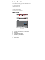
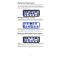
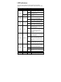
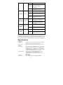
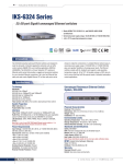
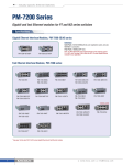
Moxa PowerTrans Switch
PT-7710 Series
Hardware Installation Guide
Third Edition, July 2010
© 2010 Moxa Inc. All rights reserved.
Reproduction without permission is prohibited.
Fl.4, No.135, Lane 235, Pao-Chiao Rd. Shing Tien City, Taipei, Taiwan,
R.O.C.
TEL: +886-2-8919-1230
P/N: 1802077100012
Package Checklist
The Moxa PowerTrans switch is shipped with the following items. If any of
these items are missing or damaged, please contact your customer service
representative for assistance.
y 1 Moxa PowerTrans Switch
y Hardware Installation Guide
y CD-ROM with User’s Manual and SNMP MIB file
y Moxa Product Warranty Statement
y RJ45 to DB9 console port cable
y Protective caps for unused ports
y 2 rack-mount ears or wall-mount ears
Panel Layout
1
3
2
4
6
6
8
M1
3
5
7
2
4
6
8
1
3
1
STAT
PWR1
PWR2
FAULT
MASTER
COUPLER
LNK/ACT
SPEED
FDX/HDX
MODE
RING PORT
COUPLER
PORT
6
8
3
5
7
3
5
2
1
7
M1
5
4
6
8
10
PT-7710
M2
2
2
2
1
1
3
5
7
1
42
Front View (Front Cabling)
8
CONSOLE
PT-7710
9
Rear View (Front Cabling)
11
2
4
6
8
M1
1
STAT
PWR1
3
MASTER
5
7
6
8
5
7
PWR2
2
FAULT
COUPLER
LNK/ACT
SPEED
FDX/HDX
MODE
RING PORT
COUPLER
PORT
M2
1
4
3
5
Top View (Down Cabling)
1.
System status LEDs
2.
Interface Module mode LEDs
3.
Interface Module port LEDs
4.
Push-button switch to select mode for Interface Module
5.
Model Name
6.
Fast Ethernet Interface Modules
7.
Gigabit Ethernet Interface Modules
8.
Serial Console port
9.
10-pin terminal block for power inputs, and relay output
10.
Rack Mounting Kit
11.
Wall Mounting Kit
-2-
44
31.8
Dimensions (unit = mm)
195
209.4
219.3
24.3
Rear View
266.5
Top View
Side View
Side View
44
31.8
31.8
462.5
Front View
Fast Ethernet Interface Modules
(for slot 1)
40.7
PM-7200-4MSC2TX/PM-7200-4SSC2TX
PM-7200-1LSC6TX
96.8
PM-7200-2MSC4TX/PM-7200-2SSC4TX
PM-7200-4MST2TX
96.8
96.8
40.7
40.7
96.8
PM-7200 1MST6TX
PM-7200-2MST4TX
PM-7200-6MST
96.8
96.8
40.7
40.7
96.8
PM-7200 1SSC6TX/1MSC6TX
PM-7200-4M12
PM-7200-8SFP
96.8
PM-7200 4MST-FL
96.8
40.7
40.7
96.8
40.7
PM-7200-6MSC/PM-7200-6SSC
40.7
40.7
96.8
40.7
96.8
40.7
40.7
PM-7200-8TX
40.7
96.8
96.8
PM-7200 8MTRJ
40.7
96.8
PM-7200 2MTRJ
-3-
40.7
96.8
PM-7200 6MTRJ
86.6
86.6
PM-7200-2GTXSFP
86.6
PM-7200 1MST
40.7
40.7
PM-7200 1MSC/1SSC
86.6
PM-7200 2MSC/2SSC
40.7
40.7
40.7
Gigabit/Fast Ethernet Interface
Modules (for slot 2)
86.6
PM-7200 2MST
Rack Mounting
Use four screws to attach the PT switch to a standard rack.
Use four screws to attach the PT switch to a
standard rack.
Wall Mounting
Use four screws to attach the PT switch to a Moxa wall mounting kit.
Wiring Requirements
WARNING
Safety First!
Be sure to disconnect the power cord before installing and/or
wiring your Moxa PowerTrans Switch.
Calculate the maximum possible current in each power wire and
common wire. Observe all electrical codes dictating the
maximum current allowable for each wire size.
If the current goes above the maximum ratings, the wiring could
overheat, causing serious damage to your equipment.
Grounding Moxa PowerTrans Switch
Grounding and wire routing help limit the effects of noise due to
electromagnetic interference (EMI). Run the ground connection from the
ground screw to the grounding surface prior to connecting devices.
-4-
Wiring the Power Inputs
The PT series of switches supports dual redundant power supplies (DC power
only): VDC “Power Supply 1 (PWR1)” and “Power Supply 2 (PWR2)”, or
VAC “Power Supply (PWR1)”. The connections for PWR1, PWR2 and the
RELAY are located on the terminal block. The front view of the terminal block
connectors are shown below.
Wiring the Relay Contact
Each PT switch has one relay output. Refer to the next section for detailed
instructions on how to connect the wires to the terminal block connector, and
how to attach the terminal block connector to the terminal block receptor.
FAULT: The relay contact of the 10-pin terminal block connector are used to
detect user-configured events. The two wires attached to the RELAY contacts
form an open circuit when a user-configured event is triggered. If a
user-configured event does not occur, the RELAY circuit will be closed.
Wiring the Redundant Power Inputs
Each PT switch has two sets of power inputs: power input 1 and power input 2.
STEP 1: Insert the dual set positive/negative DC wires into PWR1 and PWR2
terminals (+ → pins 1, 9, - → pins 2, 10). Or insert the L/N AC wires into
the PWR1 terminals (L → pin 1, N → pin 2).
STEP 2: To keep the DC or AC wires from pulling loose, use a screwdriver to
tighten the wire-clamp screws on the front of the terminal block connector.
-5-
LED Indicators
The front panel of the PT switch contains several LED
indicators. The function of each LED is described in the table
below.
LED
Color
State
System LEDs
System has passed self-diagnosis test
on boot-up and is ready to run.
On
GREEN
Blinking
STAT
RED
PWR1
PWR2
FAULT
MSTR/HEAD
CPLR/TAIL
System failed self-diagnosis on
boot-up.
On
Power is being supplied to the main
module’s power input PWR1.
Off
Power is not being supplied to the
main module’s power input PWR1.
On
Power is being supplied to the main
module’s power input PWR2.
Off
Power is not being supplied to the
main module’s power input PWR2.
On
The corresponding PORT alarm is
enabled and a user-configured event
has been triggered.
Off
The corresponding PORT alarm is
enabled and a user-configured event
has not been triggered, or the
corresponding PORT alarm is
disabled.
On
This PT switch is set as the Master
of the Turbo Ring, or as the Head of
the Turbo Chain.
AMBER
RED
GREEN
System is undergoing the
self-diagnosis test.
On
AMBER
GREEN
Description
The PT switch has become the Ring
Master of the Turbo Ring, or the
Blinking Head of the Turbo Chain, after the
Turbo Ring or the Turbo Chain went
down.
Off
The PT switch is not the Master of
this Turbo Ring or is set as a
Member of the Turbo Chain.
On
When this PT switch is enabled to
form a back-up path, or it is set as
the Tail of the Turbo Chain.
Blinking Turbo Chain is down.
Off
This PT switch disabled the coupling
function, or is set as a Member of the
Turbo Chain.
Mode LEDs
LNK/ACT
GREEN
On
The corresponding module
-6-
Blinking
Off
port’s link is active.
The corresponding module
port’s data is being
transmitted.
The corresponding module
port’s link is inactive.
The corresponding module port’s
data is being transmitted at 10 Mbps.
The corresponding module port’s
On
data is being transmitted at 100
Mbps.
The corresponding module port’s
Blinking data is being transmitted at
1000 Mbps.
The corresponding module port’s
On
data is being transmitted in full
duplex mode.
The corresponding module port’s
Off
data is being transmitted in half
duplex mode.
The corresponding module’s port is
On
the ring or chain port of this PT
switch.
The corresponding module’s port is
Off
not the ring or chain port of this PT
switch.
The corresponding module’s port is
On
the coupler port of this PT switch.
The corresponding module’s port is
Off
not the coupler port of this PT
switch.
Off
SPEED
GREEN
FDX/HDX
GREEN
RING/CHAIN
PORT
GREEN
COUPLER
PORT
GREEN
* Slot 2 (M2) is mainly used for Gigabit modules. If
100BaseFX modules are used in Slot 2 (M2), the modules will
not support “Far End Fault”. The Link/ACT LED indicator will
stay at “Green (ON)” status when Fiber TX cable is unplugged.
Specifications
Technology
Standards
Flow control
Interface
Fast Ethernet
Gigabit Ethernet
Console
System LED
IEEE 802.3, 802.3u, 802.3ab, 802.3z, 802.3x, 802.1D,
802.1W, 802.1Q, 802.1p, 802.1X, 802.3ad
IEEE 802.3x flow control, back pressure flow control
Slot 1 (M1) for any combination of 4-,6-, 7-, or 8-port
PM-7200 fast Ethernet modules with 10/100BaseT(X)
(TP/M12 interface) or 100BaseFX (SC/ST connector),
or 100BaseSFP; Slot 2 (M2) for a 1- or 2-port interface
modules with 100BaseFX (SC/ST connector)
Slot 2 (M2) for 2-port PM-7200 Gigabit Ethernet
combo module with 100/1000BaseT(X) or
1000BaseSFP slots (Slot 2 does not support 10M
FDX/HDX)
RS-232 (RJ45)
STAT, PWR1, PWR2, FAULT, MSTR/HEAD,
-7-
Indicators
Mode LED
Indicators
Alarm Contact
CPLR/TAIL
LNK/ACT, FDX/HDX, RING/CHAIN PORT,
COUPLER PORT, SPEED
One relay output with current carrying capacity of 3A
@ 30 VDC or 3A @ 240 VAC
Optical Fiber (100BaseFX)
Distance
Multi-mode
0 to 5 km, 1300 nm (50/125μm, 800 MHz*km)
0 to 4 km, 1300 nm (62.5/125μm, 500 MHz*km)
Single-mode
0 to 40 km, 1310 nm (9/125μm, 3.5 PS/(nm*km))
Min. TX Output
Multi-mode: -20 dBm; single-mode: -5 dbm
Max. TX Output
Multi-mode: -10 dBm; single-mode: 0 dbm
RX Sensitivity
Multi-mode: -32 dBm; single-mode: -34 dbm
Power
Input Voltage
24/48 VDC (9 to 60 V), or 110/220 VDC/VAC (88 to
300 VDC and 85 to 264 VAC)
Input Current
Max. 0.81A @ 24 VDC
Max. 0.42A @ 48 VDC
Max. 0.17/0.10 @ 110/220 VDC
Max. 0.20/0.12 @ 110/220 VAC
Physical Characteristics
Housing
IP 30 protection, metal case
Dimensions
266.7 x 44 x 195 mm (10.5 x 1.73 x 7.68 in.)
(W x H x D)
Weight
2200g
Regulatory Approvals
Operating Temp.
-40 to 85°C (-40 to 185°F)
Cold start of min. 100 VAC at -40°C
Storage Temp.
-40 to 85°C (-40 to 185°F)
Ambient Relative
5 to 95% (non-condensing)
Humidity.
Regulatory Approvals
Safety
EN60950-1
Power Automation IEC 61850-3, IEEE 1613
Road Traffic
NEMA TS2
Rail Traffic
EN50121-4
EMI
FCC Part 15, CISPR (EN55022) class A
5 years
Warranty
Technical Support Contact Information
www.moxa.com/support
Moxa China (Shanghai office):
Toll-free: 800-820-5036
Tel:
+86-21-5258-9955
Fax:
+86-10-5258-5505
Moxa Americas:
Toll-free: 1-888-669-2872
Tel:
+1-714-528-6777
Fax:
+1-714-528-6778
Tel:
Fax:
Moxa Europe:
+49-89-3 70 03 99-0
+49-89-3 70 03 99-99
Tel:
Fax:
-8-
Moxa Asia-Pacific:
+886-2-8919-1230
+886-2-8919-1231