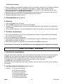
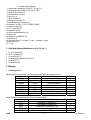
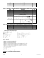
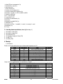
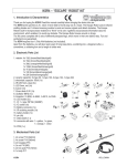
1
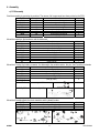
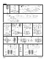
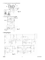
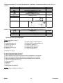
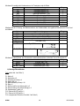
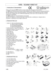
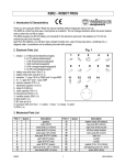
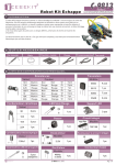
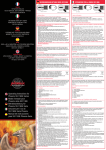
KSR6 – "LADYBUG" ROBOT KIT
1. Introduction & Characteristics
Thank you for buying the KSR6! Read this manual carefully before bringing the device into use.
The KSR6 uses infrared emitting diodes as "eyes" to avoid obstacles in its path. The Ladybug automatically makes a
left turn when it detects an object. It continues to move forward as long as there's no detection.
The Kit comes complete with 2 sets of differently designed legs, which move in their own distinct way. Fun and
excitement are guaranteed.
The KSR6 requires four 1.5Vdc AAA-batteries (not included).
Apart from the batteries, you will also need a pair of long-nose pliers, a soldering iron, a diagonal cutter, a
screwdriver, a soldering iron and a length of solder wire.
2. Electronic Parts List
Fig. 1
1. resistor: 1x 10Ω (brown/black/black/gold)
2x 15Ω (brown/green/black/gold)
2x 100Ω (brown/black/brown/gold)
1x 1K (brown/black/red/gold)
4x 4K7 (yellow/purple/red/gold)
3x 10K (brown/black/orange/gold)
3x 120K (brown/red/yellow/gold)
1x 1.8M (brown/grey/green/gold)
2. ceramic capacitor: 1x type 331, 4x type 104
3. electrolytic capacitor: 1x 4.7µf, 2x 100µf
4. IR emitting diode 5mm, clear (1x)
5. photo transistor, black (1x)
6. black tube (1x)
7. diode 1N4148 (1x)
8. pin header 4 pins (1x)
9. female pin header 4 pins (1x)
10. transistor: 3x C945, 1x A733, 2x 8050, 2x 8550
11. LED holder (2x)
12. IC: 1x type LM324 (14 pins)
13. IC socket 14 pins (1x)
14. battery connector (1x)
15. pin (4x)
16. variable resistor 50K (1x)
17. slide switch (1x)
18. connector with wire: 1 x yellow, 1 x green,
1 x orange, 1 x blue
19. battery holder (1x)
20. PCB (1x)
3. Mechanical Parts List
1. 2x screw 3x6mm (P13)
2. 9x screw 3x6mm (P14)
3. 3x nut M3 (P15)
4. 4x hex post 10mm (P16)
5. 1x body (P17)
6. 2x antenna (P18)
KSR6
Fig. 2
1
VELLEMAN
4. Assembly
a) PCB Assembly
Start the assembly by mounting the resistors. The names of all components have been printed on the PCB:
Part ID
R11
R12/17
R13/16
R1
R4/9/10/15
R2/3/5
R6~8
R14
Description
10Ω
15Ω
100Ω
1K
4K7
120K
10K
1.8M
Colour Code
brown/black/black/gold
brown/green/black/gold
brown/black/brown/gold
brown/black/red/gold
yellow/purple/red/gold
brown/red/yellow/gold
brown/black/orange/gold
brown/grey/green/gold
Quantity
1
2
2
1
4
3
3
1
Mount the capacitors, the transistors and the diode next:
Part ID
C1
C2/3
EC3
EC1/2
Q1/2/7
Q8
Q4/5
Q3/6
D1
Description
ceramic capacitor 331
ceramic capacitor 104
electrolytic capacitor 0.47µf
electrolytic capacitor 100µf
transistor C945
transistor A733
transistor 8050
transistor 8550
diode 1N4148
Quant.
1
2
1
2
3
1
2
2
1
Mount the IC socket, the battery connector, the slide switch, the variable resistor, the pins, the IC and the pin header.
Part ID
IC1
BAT.
SW.
VR1
M1 (+/-)
M2 (+/-)
IC1
To IR_PCB
Description
IC socket (fig.1 #13)
battery connector (fig.1 #14)
slide switch (fig.1 #17)
variable resistor (fig.1 #16)
Quant.
1
1
1
1
pins (fig.1 #15)
4
type LM324
1
pin header (fig. 1 #8)
1
Mount the IR emitting diode, the photo transistor and the female header:
Part ID
TX_IR
RX_IR
From Main_Board
Description
IR emitting diode (fig. 1 #4)
photo transistor (fig. 1 #5)
female header (fig. 1 #9)
Quantity
1
1
1
Fig. 3b
Fig. 3a
KSR6
2
VELLEMAN
b) Gearbox Assembly
Parts
P1: motor x 2
P2: motor holder x 2
P3: screw (2x10mm) x 4
Fig. 4
P4: nut (M2) x 4
P5: tapping screw (3x7mm) x 34
P6: eyelet x 6
P7: gear (44T+0) with shaft (green) x 2
P8: gear (44T+0) with shaft (orange) x 4
P9: pinion gear 8T (white) x 2
P10: gear 48/18T (white) x 2
P11: gear 44/18T (blue) x 4
P12: clear tube x 2
Fig. 5
A: gear protection plates (2)
B: motor protection plates (2)
C: protection plates (4) for corner wheel/leg gears
D: gear brackets (2) for corner wheel/leg gears
E: gear brackets (2) for corner wheel/leg gears
F: motor mounting bracket (1)
G: top plate (1)
H: wheels (6)
I: legs (6)
J: rubber feet for legs (6)
KSR6
3
VELLEMAN
Assembly
OR
OF
OU
O
ODER
KSR6
4
VELLEMAN
c) Mechanical Assembly
1. Mount the wires and the ceramic capacitors type 104 on the motors and fix the antennae on the small PCB.
The colour code used for the wires is: 1=green, 2=yellow, 3=orange, 4=blue
wires / capacitors
antennae
Fig. 7
Fig. 6
2. Attach the battery holder and the small PCB onto the main PCB (see
figure 8). Connect the battery holder to the battery connector (BAT, see
"4.a) PCB assembly").
Fig. 8
3. Fix the PCB to the gearbox and put the wires through the holes at the
right side of the device.
Fig. 9
KSR6
5
VELLEMAN
4. Connect the wires to the pins on the M-terminals:
Fig. 10
5. Mount the body to the rest of the KSR6.
Fig. 11
5. Wiring Diagram
Fig. 12
KSR6
6
VELLEMAN
6. Operation
1.
2.
3.
4.
Put the switch in the “ON”-position.
Put the KSR6 on the ground ; it should start moving forward.
When it detects an obstacle, it will turn to the left. As long as there is no obstacle, it will continue to move forward.
Adjust the variable resistor and thus the detection distance (to the left = higher sensitivity, to the right = lower).
7. Troubleshooting
1. Make sure all components on the PCB are in the right position. Pay particular attention to the polarity of the IR diode
and the photo transistor.
2. Make sure the wiring is connected correctly.
3. The sensitivity may be affected by fading battery power. Adjust the variable resistor to improve the range.
4. Apply a little bit of machine oil to the axles of the gears if the KSR6 isn't running smoothly.
Note: The specifications and contents of this manual can be subject to change without prior notice.
KSR6 – "LADYBUG" ROBOT KIT
1. Inleiding & Kenmerken
Dank u voor uw aankoop! Lees deze handleiding aandachtig voor u het toestel in gebruik neemt.
De KSR6 maakt gebruik van infrarood-diodes als 'ogen' om obstakels op zijn weg te omzeilen. De Ladybug draait
automatisch naar links wanneer het een voorwerp detecteert. Het blijft vooruit bewegen zolang er geen detectie is.
De Kit wordt geleverd met 2 verschillende sets poten, die elk op een verschillende manier bewegen. Plezier verzekerd!
De KSR6 werkt op vier AAA-batterijen van 1.5V (niet meegeleverd).
Behalve de batterijen heeft u ook een bektang, een zijkniptang, een schroevendraaier, een soldeerijzer en
soldeerdraad nodig.
2. Lijst van elektronische onderdelen (zie fig. 1 blz. 1)
1. weerstand : 1x 10Ω (bruin/zwart/zwart/goud)
2x 15Ω (bruin/groen/zwart/goud)
2x 100Ω (bruin/zwart/bruin/goud)
1x 1K (bruin/zwart/rood/goud)
4x 4K7 (geel/paars/rood/goud)
3x 10K (bruin/zwart/oranje/goud)
3x 120K (bruin/rood/geel/goud)
1x 1.8M (bruin/grijs/groen/goud)
2. keramische condensator 1x type 331, 4x type 104
3. elektrolytische condensator: 1x 4.7µf, 2x 100uf
4. IR diode 5mm, helder (1x)
5. fototransistor, zwart (1x)
6. zwart buisje (1x)
7. diode 1N4148 (1x)
8. 4-pins pinheader (1x)
9. vrouwelijke 4-pins pinheader (1x)
10. transistor: 3x C945, 1x A733, 2x 8050, 2x 8550,
11. LED houder (2x)
12. IC: 1 x type LM324
13. IC voet 14-pins (1x)
KSR6
7
VELLEMAN
14. batterijconnector (1x)
15. pin (4x)
16. regelbare weerstand 50K (1x)
17. schuifschakelaar (1x)
18. connector met draad: 1 x geel, 1 x groen, 1 x oranje, 1 x blauw
19. batterijhouder (1x)
20. PCB (1x)
3. Lijst van mechanische onderdelen (zie fig. 2 blz. 1)
1.
2.
3.
4.
5.
6.
2 x schroef 3 x 6mm (P13)
9x schroef 3 x 6mm (P14)
2 x moer M3 (P15)
2 x hexag. Afstandsbus 10mm (P16)
2 x behuizing (P17)
1 x voelhoorn (P18)
4. Montage
a) Montage van de PCB
Monteer eerst de weerstanden. De namen van de componenten staan op de PCB.
Onderdeel
Beschrijving
Kleurcode
R11
bruin/zwart/zwart/goud
10Ω
R12/17
bruin/groen /zwart/goud
15Ω
R13/16
bruin/zwart/ bruin/goud
100Ω
R1
1K
bruin/zwart/rood/goud
R4/9/10/15
4K7
geel/paars/rood/goud
R2/3/5
120K
bruin/rood/geel/goud
R6~8
10K
bruin/zwart/oranje/goud
R14
1.8M
bruin/grijs/groen/goud
Hoev.
1
2
2
1
4
3
3
1
Monteer vervolgens de condensators, de transistors en de diode:
Onderdeel
Beschrijving
C1
keramische condensator 331
C2/3
keramische condensator 104
EC3
elektrolytische condensator 4,7µf
EC1/2
elektrolytische condensator 100µf
Q1/2/7
transistor C945
Q8
transistor A733
Q4/5
transistor 8050
Q3/6
transistor 8550
D1
diode 1N4148
Hoev.
1
2
1
2
3
1
2
2
1
KSR6
8
VELLEMAN
Monteer de IC voet, de batterijconnector, de schuifschakelaar, de regelbare weerstand, de pinnen, de IC en de pinheader.
Onderdeel
IC1
BAT.
SW.
VR1
M1 (+/-)
M2 (+/-)
IC1
To IR_PCB
Beschrijving
IC voet (fig.1 #13)
batterijconnector (fig.1 #14)
schuifschakelaar (fig.1 #17)
regelbare weerstand (fig.1 #16)
Hoev.
1
1
1
1
pinnen (fig.1 #15)
4
1
type LM324
pinheader (fig. 1 #8)
1
Monteer de IR diode, de fototransistor en de vrouwelijke pinheader: (zie figuren 3a en 3b op blz. 2)
Part ID
Beschrijving
Hoev
TX_IR
IR diode (fig. 1 #4)
1
RX_IR
fototransistor (fig. 1 #5)
1
From Main_Board
vrouwelijke pinheader (fig. 1 #9)
1
b) Montage tandwielkast
Onderdelen (zie fig. 4 blz. 3)
P1: motor x 2
P2: motorhouder x 2
P3: schroef (2x10mm) x 4
P4: moer (M2) x 4
P5: zelftappende schroef (3x7mm) x 34
P6: ring x 6
P7: tandwiel (44T+0) met as (groen) x 2
P8: tandwiel (44T+0) met as (oranje) x 4
P9: rondsel 8T (wit) x 2
P10: tandwiel 48/18T (wit) x 2
P11: tandwiel 44/18T (blauw) x 4
P12: doorzichtig buisje x 2
(zie fig. 5 blz. 3)
A: Beschermplaatjes voor de tandwielen (2)
B: Beschermplaatjes voor de motoren (2)
C: Beschermplaatjes (4) voor de tandwielen van de wielen/poten op de hoeken
D: Bevestigingsplaten (2) voor de tandwielen van de wielen/poten op de hoeken
E: Bevestigingsplaten (2) voor de tandwielen van de wielen/poten op de hoeken
F: Bevestigingsplaat voor de motoren (1)
G: topplaat (1)
H: wielen (6)
I: poten (6)
J: rubber voetjes voor de poten (6)
Montage (zie figuren tabel blz. 4)
KSR6
9
VELLEMAN
c) Mechanische montage
1. Monteer de draden en de keramische condensators type 104 op de motoren (zie fig.6 blz.5) en bevestig de voelhoorns
op de kleine PCB (zie fig.7 blz.5). De kleurcode voor de draden is: 1=groen, 2=geel, 3=oranje, 4=blauw
2. Bevestig de batterijhouder en de kleine PCB aan de grote PCB (zie fig.8 blz.5). Sluit de batterijhouder aan op de
batterijconnector (BAT, zie "4.a) Montage van de PCB").
3. Bevestig de PCB op de tandwielkast en leid de draden door de openingen rechts op de robot (zie fig.9 op blz.5)
4. Verbind de draden met de pinnen op de M-aansluitingen (zie fig.10 op blz.6).
5. Bevestig de behuizing (zie fig.11 op blz.6).
5. Bedradingschema (zie fig.12 blz. 6)
6. Bediening
1. Plaats de schakelaar in de “ON”-stand.
2. Plaats de KSR6 op de grond ; hij zou moeten vooruit bewegen.
3. Wanneer hij een obstakel detecteert, zal hij naar links draaien. Wanneer er geen obstakel is, zal hij altijd blijven
vooruit bewegen.
4. Stel de regelbare weerstand, en dus de detectieafstand, bij (naar links: gevoeliger, naar rechts: minder gevoelig).
7. Problemen en oplossingen
1. Ga na of alle componenten op de PCB op de juiste plaats zitten. Besteed de nodige aandacht aan de polariteit
van de IR diode en de fototransistor.
2. Ga na of de bedrading goed is aangesloten.
3. De gevoeligheid kan worden aangetast door het verminderende vermogen van de batterijen. Stel de regelbare
weerstand bij om het bereik te vergroten.
4. Smeer wat fijne machineolie op de assen van de tandwielen als de KSR6 niet soepel loopt.
De specificaties en de inhoud van de handleiding kunnen worden gewijzigd zonder voorafgaande kennisgeving.
KSR6 – KIT ROBOT "LADYBUG"
1. Introduction & caractéristiques
Nous vous remercions de votre achat ! Lisez la notice présente attentivement avant la mise en service de l'appareil.
Le KSR6 a des 'yeux' diodes IR lui permettant de contourner des obstacles dans sa route. Le Ladybug tourne
automatiquement à gauche quand il détecte un objet. Il continue en avant tant qu'il n'y a pas de détection.
Le Kit est livré avec 2 jeux de pattes bougeant d'une façon unique. Le plaisir est garanti!
Votre KSR6 marche sur 4 piles LR3 de 1.5V (non incl.).
Sauf els piles vous aurez également besoin d'une pince plate, une pince coupante, un tournevis, un fer à souder et
du fil d'apport.
2. Liste des pièces électroniques (voir fig. 1 à la p. 1)
1. résistance : 1x 10Ω (brun/noir/noir/doré)
2x 15Ω (brun/vert/noir/doré)
2x 100Ω (brun/noir/brun/doré)
1x 1K (brun/noir/rouge/doré)
4x 4K7 (jaune/pourpre/rouge/doré)
3x 10K (brun/noir/orange/doré)
3x 120K (brun/rouge/jaune/doré)
KSR6
10
VELLEMAN
1x 1.8M (brun/gris/vert/doré)
2. condensateur céramique 1x type 331, 4x type 104
3. condensateur électrolytique 1x 4.7µf, 2x 100µf
4. diode IR 5mm, claire (1x)
5. phototransistor, noir (1x)
6. tube noir (1x)
7. diode 1N4148 (1x)
8. barrette à 4 broches (1x)
9. barrette femelle à 4 broches (1x)
10. transistor: 3x C945, 1x A733, 2x 8050, 2x 8550,
11. support de LED (3x)
12. CI: 1 x type 78P156
13. support de CI (1x)
14. connecteur d'alimentation (1x)
15. broche (4x)
16. résistance variable 50K (1x)
17. glissière (1x)
18. connecteur avec fil : 1 x jaune, 1 x vert, 1 x orange, 1 x bleu
19. porte-piles (1x)
20. CI (1x)
3. Liste des pièces mécaniques (voir fig. 2 à la p. 1)
1.
2.
3.
4.
5.
6.
2x vis 3 x 6mm (P13)
9x vis 3 x 6mm (P14)
3x écrou M3 (P15)
4x entretoise hexagonale 10mm (P16)
1x boîtier (P17)
2x antenne (P18)
4. Montage
a) Montage du CI
Montez d'abord les résistances. Les noms des composants sont imprimés sur le CI.
Pièce
Description
Couleur
R11
brun/noir/noir/doré
10Ω
R12/17
brun/vert/ noir/doré
15Ω
R13/16
brun/noir/brun/doré
100Ω
R1
1K
brun/noir/rouge/doré
R4/9/10/15
4K7
jaune/pourpre/rouge/doré
R2/3/5
120K
brun/rouge/jaune/doré
R6~8
10K
brun/noir/orange/doré
R14
1.8M
brun/gris/vert/doré
Qté.
1
2
2
1
4
3
3
1
Montez ensuite les condensateurs, les transistors et la diode:
Pièce
Description
C1
condensateur céramique 331
C2/3
condensateur céramique 104
EC3
condensateur électrolytique 4.7µf
EC1/2
condensateur électrolytique 100µf
Q1/2/7
transistor C945
Qté
1
2
1
2
3
KSR6
11
VELLEMAN
Q8
Q4/5
Q3/6
D1
transistor A733
transistor 8050
transistor 8550
diode 1N4148
1
2
2
1
Montez les support de CI, connecteur d'alimentation, glissière, résistance variable, broches, CI et barrette.
Pièce
Description
Qté
IC1
support de CI (fig.1 #13)
1
BAT.
connecteur d'alimentation (fig.1 #14)
1
SW.
glissière (fig.1 #17)
1
VR1
résistance variable (fig.1 #16)
1
M1 (+/-)
broches (fig.1 #15)
4
M2 (+/-)
1
IC1
type LM324
To IR_PCB
1
barrette (fig. 1 #8)
Montez la diode IR, le phototransistor et la barrette femelle: (voir figures 3a et 3b à la page 2)
Pièce
Description
TX_IR
diode IR (fig.1 #4)
RX_IR
phototransistor (fig.1 #5)
From Main_Board
barrette femelle (fig.1 #9)
Qté
1
1
1
b) Montage de la boîte d'engrenages
Parties (voir fig. 4 à la p. 3)
P1: moteur x 2
P2: support de moteur x 2
P3: écrou (2x10mm) x 4
P4: boulon (M2) x 4
P5: vis (3x7mm) x 34
P6: oeillet x 6
P7: pignon (44T+0) avec axe (vert) x 2
P8: pignon (44T+0) avec axe (orange) x 4
P9: satellite 8T (blanc) x 2
P10: pignon 48/18T (blanc) x 2
P11: pignon 44/18T (bleu) x 4
P12: tube claire x 2
(voir fig. 5 à la p.3)
A: plaques de protection pour pignons (2)
B: plaques de protection pour moteur (2)
C: plaques de protection (4) pour les pignons des roues/pattes sur les coins
D: plaques de montage (2) pour les pignons des roues/pattes sur les coins
E: plaques de montage (2) pour les pignons des roues/pattes sur les coins
F: plaque de montage pour moteurs (1)
G: plaque supérieure (1)
H: roues (6)
I: pattes (6)
J: pied en caoutchouc pour pattes (6)
Montage: voir les figures dans le tableau sur la page 4.
KSR6
12
VELLEMAN
c) Montage mécanique
1. Montez les fils et les condensateurs céramiques type 104 sur les moteurs (voir fig. 6 à la p. 5) et les antennes sur
le petit CI (voir fig. 7 à la p. 5). Le code de couleur des fils est: 1=vert, 2=jaune, 3=orange, 4=bleu
2. Fixez le porte-piles et le petit CI sur le CI principal (voir fig. 8 à la p. 5). Connectez le porte-piles au connecteur
d'alimentation (BAT, voir "4.a) Montage du CI").
3. Montez le CI sur la boîte d'engrenages et guidez les fils à travers les trous à la droite du robot (voir fig. 9 à la p. 5)
4. Reliez les fils aux broches des connexions M (voir fig. 10 à la p. 6).
5. Assemblez le boîtier (voir fig.11 à la p. 6).
5. Câblage (voir fig.12 à la p. 6)
6. Opération
1.
2.
3.
4.
Mettez l'interrupteur dans la position “ON”.
Mettez le KSR6 sur le sol ; il commencera à bouger en avant.
Quand il détecte un obstacle, il tourne automatiquement à gauche. S'il n'y a pas d'obstacle, il continue tout droit.
Réglez la résistance variable pour modifier la distance de détection (vers la gauche: plus sensible, vers la droite:
moins sensible).
7. Problèmes et solutions
1. Vérifiez si chaque composant du CI a été monté au bon endroit. Contrôlez la polarité de la diode IR et le
phototransistor.
2. Veillez à ce que tout câblage soit correctement connecté.
3. La sensibilité peut diminuer quand les piles deviennent faibles. Augmentez la portée avec la résistance variable.
4. Lubrifiez les axes des pignons avec un peu d'huile de graissage fine si votre KSR6 ne bouge pas aisément.
Les spécifications et le contenu de la notice peuvent être modifiées sans notification préalable.
KSR6 – KIT ROBOT "LADYBUG"
1. Introducción & características
¡Gracias por haber comprado el KSR6! Lea cuidadosamente las instrucciones del manual antes de montarlo.
El KSR6 utiliza diodos de emisión IR como "ojos" para evitar obstáculos. El "Ladybug" gira automáticamente a la
izquierda al detectar un obstáculo. Avanza siempre en línea recta mientras no haya obstáculo.
El Kit se entrega con 2 juegos de patas que se mueven de forma única. ¡Diversión asegurada!
El KSR6 funciona con 4 pilas AAA de 1.5V (no incl.).
Además de las pilas necesitará también unos alicates de punta plana larga, unos alicates de corte, un destornillador,
un soldador e hilo de estaño.
2. Lista de piezas electrónicas (véase fig. 1 en la p. 1)
1. resistencia : 1x 10Ω (marrón/negro/negro/dorado)
2x 15Ω (marrón/verde/negro/dorado)
2x 100Ω (marrón/negro/marrón/dorado)
1x 1K (marrón/negro/rojo/dorado)
4x 4K7 (amarillo/morado/rojo/dorado)
3x 10K (marrón/negro/naranja/dorado)
3x 120K (marrón/rojo/amarillo/dorado)
1x 1.8M (marrón/gris/verde/dorado)
2. condensador cerámico 1x tipo 331, 4x type 104
3. condensador electrolítico 1x 4.7µf, 2x 100µf
KSR6
13
VELLEMAN
4. diodo IR 5mm, transparente (1x)
5. fototransistor, negro (1x)
6. tubo negro (1x)
7. diodo 1N4148 (1x)
8. conector, de 4 contactos (1x)
9. conector hembra de 4 contactos (1x)
10. transistor: 3x C945, 1x A733, 2x 8050, 2x 8550,
11. soporte de LED (3x)
12. CI: 1 x tipo 78P156
13. soporte de CI (1x)
14. conector de alimentación (1x)
15. polo (4x)
16. resistencia variable 50K (1x)
17. deslizador (1x)
18. conector con hilos : 1 x amarillo, 1 x verde, 1 x naranja, 1 x azul
19. portapilas (1x)
20. CI (1x)
3. Lista de piezas mecánicas (véase fig. 2 en la p. 1)
1.
2.
3.
4.
5.
6.
2x tornillo 3 x 6mm (P13)
9x tornillo 3 x 6mm (P14)
3x tornillo M3 (P15)
4x separador hexagonal 10mm (P16)
1x caja (P17)
2x antena (P18)
4. Montaje
a) Montaje del CI
Primero, monte las resistencias cuyos nombres están impresos en el CI.
Pieza
Descripción
Color
R11
marrón/negro/negro/dorado
10Ω
R12/17
marrón/verde/ negro/dorado
15Ω
R13/16
marrón/negro/marrón/dorado
100Ω
R1
1K
marrón/negro/rojo/dorado
R4/9/10/15
4K7
amarillo/morado/rojo/dorado
R2/3/5
120K
marrón/rojo/amarillo/dorado
R6~8
10K
marrón/negro/naranja/dorado
R14
1.8M
marrón/gris/verde/dorado
Cantidad
1
2
2
1
4
3
3
1
Luego, monte los condensadores, los transistores y el diodo:
Pieza
Descripción
C1
condensador cerámico 331
C2/3
condensador cerámico 104
EC3
condensador electrolítico 4.7µf
EC1/2
condensador electrolítico 100µf
Q1/2/7
transistor C945
Q8
transistor A733
Q4/5
transistor 8050
Q3/6
transistor 8550
D1
diodo 1N4148
Cantidad
1
2
1
2
3
1
2
2
1
KSR6
14
VELLEMAN
Monte los soportes del CI, el conector de alimentación, el deslizador, la resistencia variable, los polos, el CI y el
conector.
Pieza
Descripción
Cantidad
IC1
soporte del CI (fig.1 #13)
1
BAT.
conector de alimentación (fig.1 #14)
1
SW.
deslizador (fig.1 #17)
1
VR1
resistencia variable (fig.1 #16)
1
M1 (+/-)
polos (fig.1 #15)
4
M2 (+/-)
1
IC1
tipo LM324
To IR_PCB
1
conector (fig. 1 #8)
Monte el diodo IR, el fototransistor y el conector hembra: (véase figuras 3a y 3b en la p. 2)
Pieza
Descripción
TX_IR
diodo IR (fig.1 #4)
RX_IR
fototransistor (fig.1 #5)
From Main_Board
conector hembra (fig.1 #9)
Cantidad
1
1
1
b) Montaje de la caja de engranajes
Partes (véase fig. 4 en la p. 3)
P1: motor x 2
P2: soporte del motor x 2
P3: tornillo (2x10mm) x 4
P4: tuerca (M2) x 4
P5: tornillo (3x7mm) x 34
P6: anillo x 6
P7: piñón (44T+0) con eje (verde) x 2
P8: piñón (44T+0) con eje (naranja) x 4
P9: satélite 8T (blanco) x 2
P10: piñón 48/18T (blanco) x 2
P11: piñón 44/18T (azul) x 4
P12: tubo transparente x 2
(véase fig. 5 en la p.3)
A: placas de protección para piñones (2)
B: placas de protección para motor (2)
C: placas de protección (4) para los piñones de las ruedas/patas en las esquinas
D: placas de montaje (2) para los piñones de las ruedas/patas en las esquinas
E: placas de montaje (2) para los piñones de las ruedas/patas en las esquinas
F: placa de montaje para motores (1)
G: placa superior (1)
H: ruedas (6)
I: patas (6)
J: pie de goma para patas (6)
Montaje: véase las figuras en la lista p. 4.
KSR6
15
VELLEMAN
c) Montaje mecánico
1. Monte los hilos y los condensadores cerámicos del tipo 104 en los motores (véase fig. 6 en la p. 5) y las antenas
en el pequeño CI (véase fig. 7 en la p. 5). El código de colores de los hilos se indica a continuación: 1=verde,
2=amarillo, 3=naranja, 4=azul
2. Fije el portapilas y el pequeño CI al CI principal (véase fig. 8 en la p. 5). Conecte el portapilas al conector de
alimentación (BAT, véase "4.a) Montaje del CI").
3. Monte el CI en la caja de engranajes y lleve los hilos a través de los agujeros a la derecha del robot (véase fig. 9
en la p. 5)
4. Conecte los hilos a los polos de las conexiones M (véase fig. 10 en la p. 6).
5. Fije la caja (véase fig.11 en la p. 6).
5. Cableado (véase fig.12 en la p. 6)
6. Funcionamiento
1. Coloque el interruptor en la posición “ON”.
2. Coloque el KSR6 en el suelo ; empezará a avanzar.
3. Si detecta un obstáculo, girará automáticamente a la izquierda. Si no detecta un obstáculo, continuará en línea
recta.
4. Ajuste la resistencia variable para modificar la distancia de detección (hacia la izquierda: más sensible, hacia la
derecha: menos sensible).
7. Solución de problemas
1. Verifique si cada componente del CI se encuentra en la posición correcta. Controle la polaridad del diodo IR y el
fototransistor.
2. Asegúrese de que los cables estén correctamente conectados.
3. La sensibilidad puede disminuir si las pilas se debilitan. Aumente el alcance con la resistencia variable.
4. Lubrique los ejes de los piñones con un poco de aceite fino de máquina si el KSR6 no se mueve de forma
flexible.
Se pueden modificar las especificaciones y el contenido de este manual sin previo aviso.
KSR6 – "LADYBUG" ROBOTERBAUSATZ
1. Einführung & Eigenschaften
Danke für Ihren Ankauf ! Lesen Sie vor Inbetriebnahme diese Bedienungsanleitung sorgfältig durch.
Der KSR6 verwendet Infrarot-Dioden als 'Augen' um Hindernisse zu umgehen. Der 'Ladybug' dreht automatisch
nach links wenn er ein Objekt detektiert. Er geht immer geradeaus solange er nichts detektiert.
Der Bausatz wird mit 2 Sets von verschiedenen Beinen, die in ihrer Art bewegen, geliefert. Sie werden mit den
verschiedenen Bewegungen endlos Spaß und Aufregung erleben. Der KSR6 braucht vier AAA-Batterien von 1.5V
(nicht mitgeliefert).
Sie brauchen auch noch einen Lötkolben, Lötzinn, eine Spitzzange, einen Seitenschneider und einen
Schraubendreher.
2. Liste der elektronischen Teile (siehe Abb.1 Seite 1)
1. Widerstand: 1 x 10Ω (braun/schwarz/schwarz/gold)
2x 15Ω (braun/grün/schwarz/gold)
2x 100Ω (braun/schwarz/braun/gold)
KSR6
16
VELLEMAN
1x 1K (braun/schwarz/rot/gold)
4x 4K7 (gelb/violett/rot/gold)
3x 10K (braun/schwarz/orange/gold)
3x 120K (braun/rot/gelb/gold)
1x 1.8M (braun/grau/grün/gold)
2. Keramikkondensator 1 x Typ 331, 4x Typ 104
3. Elektrolytkondensator: 1x 4.7µf, 2x 100uf
4. IR-Diode 5mm, klar (1x)
5. Fototransistor, schwarz (1x)
6. schwarzes Röhrchen (1x)
7. Diode 1N4148 (1x)
8. 4-polige Stiftleiste (1x)
9. 4-polige Buchsenleiste (1x)
10. Transistor: 3x C945, 1x A733, 2x 8050, 2x 8550,
11. LED-Halter (2x)
12. IC: 1 x Typ LM324
13. IC-Fassung 14-polig (1x)
14.Batterieanschluss (1x)
15. Pin (4x)
16.regelbarer Widerstand 50K (1x)
17. Schiebeschalter (1x)
18. Anschluss mit Draht: 1 x gelb, 1 x grün, 1 x orange, 1 x blau
19.Batteriehalter (1x)
20. Leiterplatte (1x)
3. Liste der mechanischen Teile (siehe Abb. 2 Seite 1)
1.
2.
3.
4.
5.
6.
2 x Schraube 3 x 6mm (P13)
9x Schraube 3 x 6mm (P14)
2 x Mutter M3 (P15)
2 x hexag. Abstandbuchse 10mm (P16)
2 x Gehäuse (P17)
1 x Fühler (P18)
4. Montage
a) Montage der Leiterplatte
Montieren Sie zuerst die Widerstände. Die Namen der Komponenten stehen auf der Leiterplatte.
KSR6
Teil
Beschreibung
Farbcode
Menge
R11
R12/17
R13/16
R1
R4/9/10/15
R2/3/5
R6~8
R14
10Ω
15Ω
100Ω
1K
4K7
120K
10K
1.8M
braun/schwarz/schwarz/gold
braun/grün/schwarz/gold
braun/schwarz/braun/gold
braun/schwarz/rot/gold
gelb/violett/rot/gold
braun/rot/gelb/gold
braun/schwarz/orange/gold
braun/grau/grün/gold
1
2
2
1
4
3
3
1
17
VELLEMAN
Montieren Sie zunächst die Kondensatoren, die Transistoren und die Diode:
Teil
Beschreibung
C1
C2/3
EC3
EC1/2
Q1/2/7
Q8
Q4/5
Q3/6
D1
Keramikkondensator 331
Keramikkondensator 104
Elektrolytkondensator 4,7µf
Elektrolytkondensator 100µf
Transistor C945
Transistor A733
Transistor 8050
Transistor 8550
Diode 1N4148
Menge
1
2
1
2
3
1
2
2
1
Montieren Sie die IC-Fassung, den Batterieanschluss, den Schiebeschalter, den regelbaren Widerstand, die Pins, IC und
die Stiftleiste.
Teil
Beschreibung
Menge
IC1
IC-Fassung (Abb.1 #13)
1
BAT.
Batterieanschluss (Abb.1 #14)
1
SW.
Schiebeschalter (Abb.1 #17)
1
VR1
regelbarer Widerstand (Abb.1 #16)
1
4
M1 (+/-)
Pins (Abb.1 #15)
M2 (+/-)
IC1
Typ LM324
1
To IR_PCB
Stiftleiste (Abb. 1 #8)
1
Montieren Sie die IR-Diode, den Fototransistor und die Buchsenleiste: (siehe Abb. 3a und 3b auf Seite 2)
Teil
Beschreibung
Menge
TX_IR
IR-Diode (Abb. 1 #4)
1
RX_IR
Fototransistor (Abb. 1 #5)
1
From Main_Board
Buchsenleiste (Abb. 1 #9)
1
b) Montage Zahnradkasten
Teile (siehe Abb. 4 auf Seite 3)
P1: Motor x 2
P2: Motorhalter x 2
P3: Schraube (2x10mm) x 4
P4: Mutter (M2) x 4
P5: Blechschraube (3x7mm) x 34
P6: Ring x 6
P7: Zahnrad (44T+0) mit Achse (grün) x 2
P8: Zahnrad (44T+0) mit Achse (orange) x 4
P9: Getrieberad 8T (weiß) x 2
P10: Zahnrad 48/18T (weiß) x 2
P11: Zahnrad 44/18T (weiß) x 4
P12: transparentes Röhrchen x 2he Abb. 5 auf Seite 3)
KSR6
18
VELLEMAN
A: Zahnradschutzplatten (2)
B: Motorschutzplatten (2)
C: Schutzplatten für Zahnräder Außenseite/Ecken (4)
D: Befestigungsplatten Zahnräder Außenseite/Ecken (2)
E: Befestigungsplatten Zahnräder Außenseite/Ecken (2)
F: Befestigungsbügel Motor (1)
G: Hauptplatte (1)
H: Räder (6)
I: Beine (6)
J: Gummifüße (6)
Montage (siehe Abb. Seite 4)
c) Mechanische Montage
1. Montieren Sie die Kabel und die keramischen Kondensatoren des Typs 104 auf den Motoren (siehe Abb. 6 auf
Seite 5) und befestigen Sie die Fühler an der kleinen Leiterplatte (siehe Abb.7 Seite 5). Der Farbcode für die Kabel
ist: 1=grün, 2=gelb, 3=orange, 4=blau
2. Befestigen Sie den Batteriehalter und die kleine Leiterplatte an der großen Leiterplatte (siehe Abb. 8 Seite 5).
Schließen Sie den Batteriehalter an den Batterieanschluss an (BAT, siehe "4.a) Montage der Leiterplatte").
3. Befestigen Sie die Leiterplatte am Zahnradkasten und führen Sie die Leitungen durch die Öffnungen an der
rechten Seite des Roboters (siehe Abb. 9 auf Seite 5)
4. Verbinden Sie die Kabel mit den Pins in den M-Anschlüssen (siehe Abb.10 auf Seite 6).
5. Befestigen Sie das Gehäuse (siehe Abb. 11 auf Seite 6).
5. Schaltplan (siehe Abb.12 Seite 6)
6. Bedienung
1. Stellen Sie den Schalter in die “ON”-Position.
2. Stellen Sie den KSR6 auf den Boden; er sollte voraus bewegen.
3. Wenn er ein Hindernis detektiert, wird er nach links drehen. Wenn es kein Hindernis gibt, wird er immer
geradeaus bewegen.
4. Stimmen Sie den regelbaren Widerstand und also auch den Detektionsabtand ab (nach links: empfindlicher, nach
rechts weniger empfindlich).
7. Probleme und Lösungen
1. Überprüfen Sie, ob alle Komponenten auf der Leiterplatte richtig montiert sind. Achten Sie auf die Polarität der IR-Diode
und des Fototransistors.
2. Überprüfen Sie, ob die Kabel richtig angeschlossen sind.
3. Die Empfindlichkeit kann durch schwächere Batterien beeinflusst werden. Stimmen Sie den regelbaren
Widerstand ab um die Empfindlichkeit zu vergrößern.
4. Schmieren Sie die Achsen der Zahnräder mit feinem Maschinenöl wenn der KSR6 nicht störungsfrei läuft.
Alle Änderungen vorbehalten.
KSR6
19
VELLEMAN