1
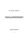
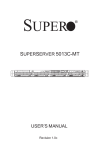
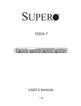
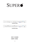
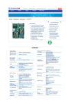
SUPER ® The SC813/SC813M Chassis Series Installation Guide Rev. 1.0b SC813/813M Chassis User's Guide Table of Contents Chapter I: Introduction ............................................................... 1-3 A. Packing Lists ............................................................................................... 1-3 B. Front Panel LED Indicators ....................................................................... 1-4 C. SC813/SC813M Chassis Specifications ................................................. 1-5 D. SC813/SC813MPower Supply Specifications ........................................ 1-6 Chapter 2: Installation Procedures ........................................... 2-1 Section 1: Installing components into the SC813 Chassis ....... 2-1 A. Removing the top Cover of the SC813 Chassis .................................. 2-1 B. Accessing the SCA Drive Tray to Install a Hard Drive ....................... 2-2 C. Rail Installation ........................................................................................... 2-3 D. Installing the Slide Assemblies into the Rack ....................................... 2-4 E. Installing the Chassis into the Rack ........................................................ 2-5 Section 2: Appendix A: SCSI (Super) GEM Driver Installation Instructions for Windows OS ............................................................ 2-6 1-2 Chapter 1: Introduction Chapter 1- Introduction A. Packing Lists A-1 The SC813 chassis The SC813 chassis contains the following: One (1) Slim CD ROM Drive [CDM-TEAC-24(B)] Four (4) SCA 1" drive trays [CSE-PT39-(B)] One (1) Slim 3.5" floppy drive [FPD-TEAC-S(B)] Two (2) 100mm Blowers [FAN-0059] One (1) Cold-swappable 500W power supply [PWS-0048] One (1) Power supply backplane [CSE-PT813-PD520 for the SC813T/S-500 Series] One (1) Power supply backplane [CSE-PT813-PD524 for the SC813T/S-500C Series] One (1) 4-port SATA backplane [CSE-SATA-813 (*for 813T)] One (1) 4-port SCSI backplane [CSE-SCA-813S (*for 813S)] The One One One One accessory box contains the following: set of motherboard screws set of drive screws set of HDD (hard disk drive) screws (1) AC power cord Rail Packaging includes: One pair of rear inner slides to be installed on the chassis One pair of outer slides to be installed in the rack Two pairs of short brackets to be used on the front side of the outer slides (Note: One pair of short brackets include screw threads, and the other pair do not. Use the only pair that will fit into your rack.) One pair of long brackets to be used on the rear side of the outer slides Optional Kits include: The SC813 Series: Riser Cards [CSE-RRIU-X] Low Profile Riser Cards [CSE-RRIU-XLP] Front Bezel [CSE-PTFB-813(B)] The SC813C Series: Riser Cards (64-Bit) [CSE-RRIU-X] Riser Cards(32-Bit) [CSE-RR32] Front Bezel [CSE-PTFB-813(B)] 1-3 SC813/813M Chassis User's Guide A-2 The SC813M chassis: The SC813M chassis contains the following: Four (4) SCA 1" drive trays [CSE-PT39(B)] One (1) 350W Power Supply [PWS-042-24] (for the 350W Series) One (1) 300 W Power Supply [PWS-0054] (for the 300W Series) One (1) 420 W Power Supply [PWS-0053] (for the 420W Series) Three (3) 40mm Fans [FAN-0061] (in the 300W & 350W Series) Four (4) 40mm Fans [FAN-0061] (in the 420W & 500W Series) One (1) 4-port SATA backplane [CSE-SATA-813] (*for the 813MT Series)] One (1) 4-port SCSI backplane [CSESCA-813S] (*for the 813MS Series)] The One One One One accessory box contains the following: set of motherboard screws set of drive screws set of HDD (hard disk drive) screws (1) AC power cord Rail Packaging includes: One pair of rear inner slides to be installed on the chassis One pair of outer slides to be installed in the rack Two pairs of short brackets to be used on the front side of the outer slides (Note: One pair of short brackets include screw threads, and the other pair do not. Use the only pair that will fit into your rack.) One pair of long brackets to be used on the rear side of the outer slides Optional Kits include: The SC813M Series: Riser Cards(64-Bit) [CSE-RRIU-X] or Riser Cards(32-Bit) [CSE-RR32-1U] Front Bezel [CSE-PTFB-813(B)] B. Front Panel LED Indicators HDD LAN1 LAN2 OH (SC813/SC813M Front Panel) 1-4 PWR On Reset SW PWR SW Chapter 1: Introduction C. Specifications of the SC813/SC813M Chassis C-1. Specifications of Model Form Factor CPU Support Max. Motherboard Size Expansion Slots SCA or HD Bays Front Side USB Port &COM port Floppy/CD-ROM Power Supply Cooling System Dimension (W x H x D) Weight Optional Kits SC813S-500/500C 1U Rackmount Dual Xeon Processors ATX 12” x 13” SC813T-500/500C 1U Rackmount Dual Xeon Processors ATX 12” x 13” 2/1 Four 1”hot-swap Ultra 320/160 SCSI drive bays (SAF-TE Compliant) Optional 2/1 Four 1”hot-swap SATA bays Yes/Yes 500W cold-swap PS Two 100mm blower fans 17.2” x 1.7” x 25.6” (437mm x 43mm x 650 mm) 35 lb. (15.9 kg) Riser Cards, Front Bezel Yes/Yes 500W cold-swap PS Two 100mm blower fans 17.2” x 1.7” x 25.6” (437mm x. 43mm x 650mm) 35 lb. (15.9 kg) Riser Cards, Front Bezel C-2. Specifications of Model Form Factor CPU Support Max. Motherboard Size Expansion Slots SCA or HD Bays Front Side USB Port & COM port Floppy/CD-ROM Power Supply Cooling System Dimension (W x H x D) Weight Optional Kits the SC813 Chassis Optional the SC813M Chassis SC813MS-350C 1U Rackmount Dual Xeon Processors ATX 12” x 10” SC813MT-350C 1U Rackmount Dual Xeon Processors ATX 12” x 10” 1 1 Four 1”hot-swap Ultra 320/160 Four 1”hot-swap SATA bays SCSI drive bays (SAF-TE Compliant) Yes Yes No/No 420W/350W/300W PS Three (3) 40mm blower fans 17.2” x 1.7” x 19.9” (437mm x 43mm x 505.5 mm) 30 lb. (13.6 kg) Riser Card, Front Bezel 1-5 No/No 420W/350W/300W PS Three (3) 40mm blower fans 17.2” x 1.7” x 19.9” (437mm x 43mm x 505.5 mm) 30 lb. (13.6 kg) Riser Card, Front Bezel SC813/813M Chassis User's Guide D. Power Supply Specifications of the SC813/SC813M Chassis D-1. Power Supply Specifications of the SC813 Chassis Power Supply Spec SC813 Mfr. Model # Mfr. Part # Rated AC Input Voltage Rated Input Frequency Rated Input Current SP502-IS PWS-048 100-240V AC 50-60 Hz 10A (115V) 5A (230V) 500W 2750 BTUs/Hr Rated Output Power Maximum rated BTU Nominal Output Vlotage +3.3V +5 +12 -5 -12 +5Vsb 20A 20A 36A N/A 1A 2A D-2. Power Supply Specifications of Serial # Mfr. Model # Mfr. Part # Rated AC Input Voltage Rated Input Frequency Rated Input Current 300W Series SP302-IS PWS-0054 100-240V AC 50-60 Hz Rated Output Power Maximum rated BTU Nominal Output Vlotage +3.3V +5V +12V1 +12V2 +12V3 +12Vtotal -5V -12V +5Vsb 300W 15A 15A 15A 15A N/A 20A N/A 1A 2A 1-6 the SC813M Chassis 350W Series FSP350-60IU PWS-042-24 100-240V AC 50-60 Hz 6A (115V) 3A (230V) 350W 1841 BTUs/Hr 420W Series SP423-IS PWS-0053 100-240V AC 50-60 Hz 20A 25A 20A N/A N/A 20A 0.3A 0.8A 2A 18A 18A 15A 15A 18A 32A N/A 1A 2A 420W Chapter 2: Installation Procedures Chapter 2: Installation Procedures Section 1: Installing Components into the SC813 Chassis A. Removing the top cover from the chassis Before installing any components, replacing chassis fans or accessing the motherboard, you will first need to remove the top cove from the chassis. Procedures 1. Press the release tabs to release the top cover from its locking position. 2. Slide the top cover out from the chassis as shown below: Slide the top cover out from the chassis Press the release buttons 3. You can now lift the side cover up and off the chassis. 2-1 SC813 Chassis User's Guide B. Accessing the SCA Drive Tray and Installing a Hard Drive To install the SCA drive into the chassis, you need to first remove the SCA drive tray from the chassis so that the SCA drive can be installed in. Procedures 1. Press the release tab to release the SCA drive tray from its locking position. 2. Pull the SCA drive tray out from the chassis as shown below: Pull out the SCA drive tray from the chassis Press the release Tab 3. Remove the two screws that attach to the both sides of the dummy tray, and take out the dummy tray as shown below: Take out the dummy tray Remove the screws 4. Slide a hard drive disk (HDD) into the SCA drive tray, and secure the HDD to the tray with three screws on each side of the tray as shown below: Secure the HDD with 3 screws on each side of the tray Slide HDD into the tray 5. Once the HDD is securely placed into the SCA tray, you can install the SCA drive tray back to the chassis. 2-2 Chapter 2: Installation Procedures C. Rail Installation Rail Packaging includes: *One pair of inner slides to be installed on the chassis, *One pair of outer slides to be installed in the rack, *Two pairs of short brackets to be used on the front side of the outer slides (Note: One pair of short brackets include screw threads, and the other pair do not. Use the only pair that will fit into your rack.), *One pair of long brackets to be used on the rear side of the outer slides C-1 Installing Inner Slides Procedures 1. Locate the right inner slide, (-the slide that will be used on the right side of chassis when facing the front panel of the chassis). 2. Align the four(4) square holes on the right inner slide against the hooks on the right side of the chassis as show below on the left. 3. Securely attach the slide to the chassis with two M4 flat head screws and repeat the steps 1-3 to install the left inner slide to the left side of the chassis. Slide the long bracket into Four(4) hooks on the right the short bracket side of the chassis Four 4 square holes on the right inner slide Adjust the distance between the brackets two M4 screws C-2 Installing Outer Slides 1. Measure the distance from the front rail of the rack to the rear rail of the rack. 2. Attach a short bracket to the rear side of the right outer slide, and a long bracket to the front side of the right outer slide as shown above on the right. 3. Adjust the short and long brackets to the proper distance so that the chassis can snugly fit into the rack. 4. Secure the slides to the cabinet with screws. left outer slide. 2-3 Repeat steps 1-4 for the SC813 Chassis User's Guide C-3 Installing the Slide Assemblies to the Rack Procedures 1. After you have installed the short and long brackets to the outer slides, you are ready to install the whole slide assemblies (-outer slides with short and long brackets attached) to the rack. (See the previous page.) 2. Use M5 screws and washers to secure the slide assemblies into the rack as shown below: Slide assemblies (-outer slides with long & short brackets attached) Secure the Slide M5 screws & washers assemblies to the rack with screws and washers 2-4 Chapter 2: Installation Procedures D. Installing the Chassis into the Rack Procedures 1. Push the inner slides, which are attached to the chassis, into the grooves of the outer slide assemblies that are installed in the rack as shown below: Inner slides Grooves of the outer slide assemblies 2. Push the chassis all the way to the back of the outer slide assemblies as shown below: (The plastic bezel is not included in the package.) Push the chassis into the back of the outer slide assemblies 2-5 SC813 Chassis User's Guide Section 2: SCSI (Super) GEM Driver Installation Instructions for Windows OS Please refer to the following instructions to install GEM Driver for the Windows OS systems. the SCSI (*Note: This driver is not necessary for other Operating Systems. If you have two SCA backplanes, you will need to install the driver twice.) The driver is located on the Super Micro motherboard driver CD or is available for download from our FTP site: ftp://ftp.supermicro.com/driver/Qlogic/ Follow the procedure below to install this driver to your system. Installing the driver: 1) Right click on “My Computer” and choose “Property”. 2) Select “Hardware” tab and click on “Device Manager”. 3) Open “Other Devices” or wherever “GEM318” is on. 4) Right click on this device and choose “Property”. 5) Click on “Driver” tab and choose “Update Driver”. 6) Click “Next” 2 times, uncheck both “Floppy disk drives” and “CD-ROM drives”. Then, select the item- “Specify a location,” and choose “Next”. 7) Click on “Browse” and choose D drive or wherever Supermicro Setup CD is in. 8) Choose “Qlogic” folder and click on “Open”. 9) System will automatically detect GEM318 and install the drive from this point on. or, 1) Right click the "My Computer" icon on your desktop and choose Properties. 2) Click on the Hardware tab and click on "Device Manager" to bring up the list of system devices. 3) You may see one or two yellow question marks (?) that read QLogic GEM354 or GEM318 SCSI Processor Device. Right click on these, and choose to uninstall. If two such question marks are present, uninstall both. 4) Click on Action tab and choose "Scan for Hardware Changes". The Hardware Wizard program should start up. Click "Next". 5) At the first prompt, choose “Display a list of known device drivers for the device so that I can choose a specific driver” and click "Next". 6) Choose “Other Devices” and click Next. 7) Choose “Have Disk”, and specify your floppy drive location in the options box. Then, click "Next". 8) Highlight “Enclosure Services Device” and click "Next". 9) Ignore the warning prompt by clicking "Yes". 2-6 Adding a Floppy Drive SC813M Chassis Adding a Floppy Drive 1-1 Overview The SC813M series of chassis includes the SC813MS-420C, the SC813MT-420C, the SC813MS-300C and the SC813MT-300C. These chassis come equipped with a front side USB/COM port tray as part of the standard configuration. Supermicro has designed the SC813M series so that the USB/COM port tray can be replaced with a slim floppy drive. This addendum describes the process involved to remove the front side USB/COM port tray and replace it with a slim floppy drive. Floppy Kit Before installing a slim floppy drive, you must obtain a floppy kit from your Supermicro representative and a slim floppy drive (not included in the kit). The items included in the floppy kit are listed below and shown in Figure 1. The floppy kit contains: One (1) floppy drive adapter Two (2) floppy drive rails One (1) floppy drive ribbon cable (to motherboard) One (1) small ribbon cable (to adapter) One (1) power cable Five (5) screws (one large, four small) 1-1 SC813M Addendum Figure 1-1. Floppy Kit Adapter (1) Power cable (1) Screws (5) Rails (2) Small ribbon cable (1) Floppy drive ribbon cable (1) 1-2 Adding a Floppy Drive 1-2 Installation Procedure Following the steps in the order given will eliminate the most common problems associated with this install. Before beginning, you should power down the system and remove the power cord. Removing the Front Panel USB/COM Port Tray 1. With the power removed from the system, first remove the top chassis cover (refer to the system manual for help). 2. A COM2 and one or two USB cables run from the tray to the motherboard. Detach these cables from the motherboard. 3. Find the release tab at the rear left of the USB/COM port tray. Push this tab in to unlock the tray, then push the tray out through the front of the chassis, along with the cables you just detached from the motherboard and which are still attached to the ports at the front of the tray. Assembling the Floppy Kit Check that all the items shown on the previous page have been included in your floppy kit. 1. Attach the two rails to the sides of the floppy drive with the four small screws. 2. Connect the small ribbon cable included in the kit to the appropriate connector on the floppy drive. 3. Use the large screw to attach the adapter to the back of the floppy drive so that the connected ribbon cable lines up with the CN1 connector on the adapter. Attach the other end of the small ribbon cable to the CN1 connector on the floppy drive adapter. 1-3 SC813M Addendum Installing the Assembled Floppy into the Chassis You are now ready to install the assembled floppy drive into the chassis 1. Insert the assembled floppy drive into the open space where the front panel tray used to be. Push it in until it locks into place. 2. Attach the white header on the floppy power cable to the drive and the black header to the floppy adapter (see Figure 1-2). 3. Connect the large (34-wire standard) floppy ribbon to the floppy adapter and route it through the chassis to connect it to the floppy connector on the motherboard. Make sure you route this cable in such a way that it does not block airflow or touch other components and is not close to any fans. 4. Replace the top chassis cover and plug in the power cord. 5. Power up the system. Press the <Del> key on system boot to access the BIOS Setup utility. In the appropriate section (usually the Main BIOS Setup) set the type of floppy installed in the "Floppy Drive" or "Legacy Diskette A" setting. 6. Exit and save changes from BIOS and allow the computer to boot up completely. 7. Insert a floppy diskette into the floppy drive and try to access it to verify it has been correctly installed. Figure 1-2. Connecting the Power Cable 1-4