1
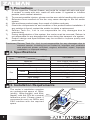
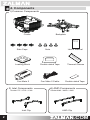
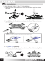
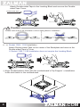
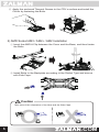
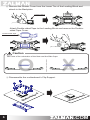
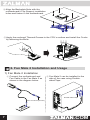
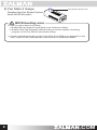
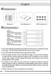
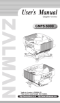
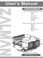
User’s Manual
CNPS8000A
Intel Socket 1366 / 1156 / 775 CPU
Core i7 Extreme
Core i7
Core i5
Core i3
Core 2 Quad
Core 2 Duo
Core 2 Extreme
Dual Core Pentium
Pentium D
Pentium 4
Celeron D
AMD Socket AM3 / AM2+ / AM2 CPU
Phenom II
Phenom
Athlon II
Athlon X2
Athlon FX
Athlon
Dual-Core Opteron
Sempron
To ensure safe and easy installation,
please read the following precautions.
www.ZALMAN.com
Ver. 1.1
1. Precautions
1)
2)
3)
4)
5)
6)
7)
8)
Do not ingest the Thermal Grease, and avoid its contact with skin and eyes.
If contact is made with skin, wash off with water. If ingested or irritation
persists, seek medical attention.
To prevent possible injuries, gloves must be worn while handling this product.
Excessive force exerted on the fan may cause damage to the fan and/or
system.
Use and keep product away from reach of children and pets.
Check the components list and condition of the product before installation. If
any problem is found, contact the retailer to obtain a replacement.
Zalman Tech Co., Ltd. is not responsible for any damages due to
overclocking.
During transportation of the system, the cooler must be removed. Zalman is
not responsible for any damages that occur during the transport of a system.
Product design and specifications may be revised to improve quality and
performance.
Disclaimer) Zalman Tech Co., Ltd. is not responsible for any damages due to
external causes, including but not limited to, improper use, problems
with electrical power, accident, neglect, alteration, repair, improper
installation, or improper testing.
2. Specifications
Spec.
Fan
Fan
Mate 2
Model
Materials
Weight
Dimensions
Bearing
w/ Fan Mate 2
RPM
w/o Fan Mate 2
Noise Level
Input Voltage
Output Voltage
Max Capacity
3. Installation Requirements
The cooler’s installation requires
an unobstructed space of 108㎜
(width), 108㎜(height), and 69㎜
(depth), with the CPU as a central
reference point. Please check if
components such as ODDs and
PSU interfere with the required
space.
1
CNPS8000A
Pure Copper, Aluminum
330g
108(L) Ⅹ 108(W) Ⅹ 66(H)㎜
2 Ball-Bearing
1,400 ~ 2,600rpm ±10%
2,800rpm ±10%
20 ~ 30dBA ±10%
12V
5 ~ 11V ±2%
less than 6W
108㎜
69㎜
108㎜
.COM
4. Components
1) Common Components
Cooler
Side Caps
Backplate
User’s Manual
Nuts
Th
er
al
G
re
as
e
Loading Block
Double-sided Tape
Thermal Grease
Fan Mate 2
Fan Mate 2 Cable
Double-sided Tape
2) Intel Components
Socket 775 / 1156 / 1366
Intel Clip
2
m
3) AMD Components
Socket AM3 / AM2+ / AM2
AMD Clip
.COM
5. Installation
1) Intel Socket 1366 / 1156 / 775 Installation
① Insert the Intel Clip between the Cover and the Base, and then fasten
the Bolts.
② Install Bolts to the Backplate according to the Socket Type and secure
with Side Caps.
Socket 775
Socket 1156
2
Socket 1366
1
Caution
Take note of the orientation of the Nuts and the Side Caps.
O
X
③ - ⓐ Socket 775 Installation
Remove the Sticker Cover from the Lower Tier of the Loading Block
and attach to the Backplate.
Loading Block
3
.COM
Attach Double-sided Tape to the Loading Block and remove the Doublesided Tape Cover.
Double-sided Tape
Caution
O
X
Please make note of the orientation of the Loading Block’s Installation.
③ - ⓑ Socket 1366 / 1156 Installation
Attach Double-sided Tape to the center of the Backplate and remove the
Double-sided Tape’s Cover.
※ Socket 1366 / 1156 Installation does not require the Loading Block.
M
ot
he
rb
oa
rd
④ Align the Backplate’s Nuts with the motherboard’s Clip Support’ s installation
holes and fasten to the motherboard.
4
.COM
⑤ Apply the enclosed Thermal Grease to the CPU’s surface and install the
Cooler by fastening the Bolts.
rboard
Mothe
2) AMD Socket AM3 / AM2+ / AM2 Installation
① Insert the AMD A Clip between the Cover and the Base, and then fasten
the Bolts.
② Install Bolts to the Backplate according to the Socket Type and secure
with Side Caps.
2
1
Caution
Take note of the orientation of the Nuts and the Side Caps.
O
5
X
.COM
③ Remove the Sticker Cover from the Lower Tier of the Loading Block and
attach to the Backplate.
Loading Block
Attach Double-sided Tape to the Loading Block and remove the Doublesided Tape Cover.
Double-sided Tape
Caution
O
Take note of the orientation of the Nuts and the Side Caps.
X
④ Disassemble the motherboard’s Clip Support.
Mo
6
rd
oa
rb
the
Mo
d
oar
rb
the
.COM
④ Align the Backplate Nuts with the
motherboard’s Clip Support installation
holes and fasten to the motherboard.
ard
rbo
e
oth
M
⑤ Apply the enclosed Thermal Grease to the CPU’s surface and install the Cooler
by fastening the Bolts.
rboard
Mothe
6. Fan Mate 2 Installation and Usage
1) Fan Mate 2 Installation
① Connect the motherboard and
Fan Cable to the Fan Mate 2 as
shown in the diagram below.
② Fan Mate 2 can be installed to the
side of the case using Doublesided Tape.
Double-sided Tape
M
ot
he
rb
oa
rd
Fan Connector (Cooler)
7
.COM
2) Fan Mate 2 Usage
Fan Speed Control Knob
Rotating the Fan Speed Control
Knob for RPM control.
BIOS booting error
In case you get a BIOS error beep:
① Rotate the Fan Speed Control Knob to its maximum setting.
② Disable CPU Fan Detected in BIOS setting or set the system monitoring
program’s CPU Fan RPM to the lowest setting.
※ Certain motherboards will not boot if the CPU fan’s RPM is not detected. In this
case, inquire to the motherboard’s manufacturer for additional details.
8
.COM