1
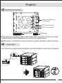
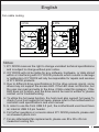
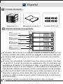
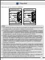
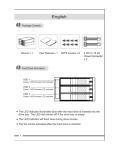
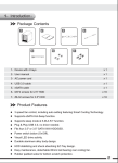
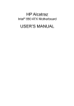
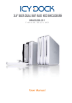
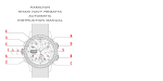
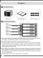
English
1
Package Contents
Device x 1
2
User Manual x 1
M3*6 screws x 8
Front Panel Information
HDD 1
Power Button
Power / Access LED Indicator
USB 3.0 Port
HDD 2
Power Button
Power / Access LED Indicator
USB 3.0 Port
HDD 3
Power Button
Power / Access LED Indicator
Fan Speed Control
HDD 4
Power Button
Power / Access LED Indicator
The LED indicator illuminates blue after the hard drive is inserted into the
drive bay. The LED will remain off if the drive bay is empty.
The LED indicator will flash blue during drive access.
The fan speed control can be switched for High, Low and Auto settings.
In High, the fan is at the maximum output, 60% of maximum in Low mode,
and in Auto mode, the fan speed will adjust according to the cooling
requirements of the drives.
The USB 3.0 and USB 3.0 port on the front of panel is made for external
device usage.ln order to make them function,please make sure to connect
the USB 3.0 and the USB 3.0 connector (for front USB 3.0 port) on the rear
to the motherboard.
The fan will turn on once a hard drive is inserted.
1
English
3
Rear Panel Information
HDD 1
HDD 2
position of USB3.0 port
of front panel
HDD 3
HDD 4
Power Port
2 Pin Fan Connector
3 Pin Fan Connector
SATA Port
The device is equipped with a 2Pin and a 3Pin connector for the fan power.
please select the compatible one for the fan replacement.
Both power connections must be used for proper operation of the enclosure.
4
Instructions
<A> Press the release button and then pull the handle to open the front panel.
386+
38//
2
English
<B> Insert the hard drive with the SATA connectors facing towards the correct
direction. Then close the door to complete the drive installation.
<C> The USB 3.0 ports on the front panel is made for external device usage.
In order to make them function, please make sure to connect the USB 3.0
header (for front USB port) on the motherboard.
ly
r Supp
Powe
rboard
Mothe
Port
SATA
19 pin 0 Port
3.
USB
5
Fan Replacement Information
z To
replace the fan, please make sure
the fan connector is compatible to the
2-PIN or 3-PIN connections of the device.
3
English
Fan cable routing
3 PIN
2 PIN
Notes:
1. ICY DOCK reserves the right to change unrelated technical specifications
and is subject to change without prior notice.
2. ICY DOCK will not be liable for any software, hardware, or data stored
within or interfacing with ICY DOCK products which results in damage
or malfunction. ICY DOCK will only be responsible for repairs and services
of ICY DOCK products.
3. Due to different drive specifications for the drive access signal, some
drives may not support the access LED. If the LED does not function, but
the user can read and write to the drive, it falls under this category. If the
LED does not function, and the drive cannot be read or written to, please
contact us for troubleshooting.
4. To utilize the hot swap function, the host must also support hot swap.To
check if your host supports hot swap, please refer to the motherboard or
controller card specifications and user manual.
5. In order to use the front USB 3.0 port, the motherboard used must have
an internal USB 3.0 pin header.
6. For further questions or concerns about ICY DOCK products, please visit
us at www.icydock.com
7. For any aftermarket fan replacements, please use 80 x 80 x 25 mm
measured cooling fan.
4
ES
1
Español
Contenido del paquete
Dispositivo x 1
2
Manual del usuario x 1
Tornillos M3*6 x 8
Información relacionada con el panel frontal
HDD 1
BOTÓN DE ALIMENTACIÓN
INDICADOR LED DE
ALIMENTACIÓN / ACCESO
HDD 2
USB 3.0 Port
BOTÓN DE ALIMENTACIÓN
INDICADOR LED DE
ALIMENTACIÓN / ACCESO
HDD 3
USB 3.0 Port
BOTÓN DE ALIMENTACIÓN
INDICADOR LED DE
ALIMENTACIÓN / ACCESO
Control de velocidad del ventilador
HDD 4
BOTÓN DE ALIMENTACIÓN
INDICADOR LED DE
ALIMENTACIÓN / ACCESO
El indicador LED se ilumina en color azul cuando la unidad de disco duro se
inserta en la bahía de unidad y permanece apagado si dicha bahía está vacía.
El indicador LED parpadea en color azul cuando se accede a la unidad de
disco duro.
El control de velocidad del ventilador tiene tres valores posibles: Alta, Baja
y Automática. Cuando la velocidad se establece en Alta, el rendimiento del
ventilador es el máximo; si se establece en Baja, el rendimiento del ventilador
será del 60% respecto al valor máximo; y si se establece en Automática, la
velocidad del ventilador se ajustará conforme a la temperatura de las unidades.
Los dos puertos USB 3.0 del frontal del panel están destinados al uso de
dispositivos externos. Para utilizar este tipo de dispositivos, conecte los
conectores USB 3.0 (para el puerto USB 3.0 delantero) a la parte trasera
de la placa base.
El ventilador se activa cuando la unidad de disco duro se inserta.
5
ES
3
Español
Información del panel posterior
HDD 1
HDD 2
HDD 3
HDD 4
Toma de alimentación
posición del puerto
USB 3.0 del panel frontal
Conector para ventilador de
2 contactos
Conector para ventilador de
3 contactos
Puerto SATA
El dispositivo está equipado con dos conectores de 2 y 3 pines respectivamente
para la alimentación del ventilador. Seleccione el conector compatible para
conectar el ventilador de sustitución.
Utilice las dos conexiones de alimentación para un correcto funcionamiento
del dispositivo.
4
Instrucciones
<A> Presione el botón de liberación y, a continuación, tire del asa para abrir
el panel frontal.
386+
38//
6
ES
Español
<B> Inserte el disco duro con los conectores SATA mirando en la dirección
correcta. Cierre a continuación la tapa para completar la instalación del
dispositivo.
<C> Los puertos USB 3.0 del panel frontal están destinados al uso de
dispositivos externos. Para utilizar este tipo de dispositivos, asegúrese de
conectar el cabezal USB 3.0 (del puerto USB delantero) a la placa base.
ly
r Supp
Powe
rboard
Mothe
Port
SATA
19 pin 0 Port
3.
USB
5
Información de sustitución del ventilador
z Para
reemplazar el ventilador,
asegúrese de que el conector
del mismo es compatible con
las conexiones de 2 o 3
contactos del dispositivo.
7
ES
Español
Colocación de los cables del ventilador
3 CONTACTOS
2 CONTACTOS
Nota:
1. ICY DOCK se reserva el derecho de cambiar las especificaciones técnicas
no relacionadas y está sujeto a cambio sin previo aviso.
2. ICY DOCK no asumirá ninguna responsabilidad por ningún software, hardware
o dato almacenado en los productos ICY DOCK, o que interactúe con estos,
que provoque daños o averías. ICY DOCK solamente asumirá la responsabilidad
de reparaciones y tareas de servicio de productos ICY DOCK.
3. Debido a las diferentes especificaciones de las unidades para la señal de
acceso a dichas unidades, algunas de estas puede que no admitan el LED
de acceso. Si el LED no funciona pero el usuario puede realizar operaciones
de lectura y escritura en la unidad, dicho LED se encuentra dentro de esta
categoría. Si el LED no funciona y no se pueden realizar operaciones de
lectura o escritura en la unidad, póngase en contacto con nosotros para
solucionar el problema.
4. Para utilizar la función de intercambio en caliente, el dispositivo principal también
debe admitir esta función. Para comprobar sea el dispositivo principal admite
la función de intercambio en caliente, consulte las especificaciones y el manual
del usuario de la placa base o de la tarjeta controladora.
5. Para utilizar el puerto USB 3.0 delantero, la placa base utilizada debe
estar equipada con un cabezal de pines USB 3.0.
6. Si tiene más preguntas o dudas acerca de los productos ICY DOCK,
visite nuestro sitio Web en www.icydock.com
7. Para cualquier sustitución posterior del ventilador, utilice un ventilador de
refrigeración con las siguientes dimensiones: 80 x 80 x 25.
8