Transcript
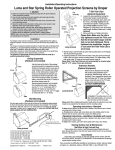
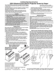
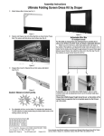
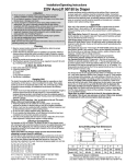
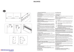
Installation Instructions
Cineperm Permanently Tensioned Projection Screen by Draper
④ Attach frame to wall using appropriate fasteners for mounting surface
(provided by others).
NOTE: Measure screen frame width at the top, bottom, and center; Make
sure the frame is installed so the center width is same as the width at
the top and bottom.
Drill through frame for
mounting hardware.
Enlarge first hole for screw
head to pass through.
Caution
① Read instructions through completely before proceeding.
② Follow instructions carefully. Installation contrary to instructions
invalidates warranty.
③ Bent or warped frames will affect surface flatness and image quality.
④ Screen should be square, and width should not vary from the center to
the ends of the frame
⑤ When lifting assembled screen, do not lift at only one corner; lift at both
corners. Lifting by one corner could result in damage to the screen
frame, especially on large screens.
⑥ Screen should be installed level (using a carpenter’s level).
⑦ Nothing should be fastened to screen frame or viewing surface.
⑧ Be careful not to rip screen material when attaching surface to frame.
⑨ The ideal temperature range for assembling this screen to prevent
damaging the surface is 68°-78° F (20°-26° C). Assembling below
recommended temperatures may damage surface and void warranty.
NOTE: Screen has been inspected and tested at factory prior to shipment.
Supporting structure
Cineperm
frame
Frame Assembly
Standard Frame—
① Lay out frame pieces on floor, by matching up color-coded tape near
corners. Snaps should be facing up.
② Assemble frame (see Fig. 1). If necessary gently tap frame ends with a
rubber mallet to make sure castings are fully seated.
Truss Frame—
① Unfold and lay out pieces on floor, by matching up color coded marks.
Lock all hinges (see Fig. 1). Stage Left and Stage Right sections should be
placed with snaps up. Top and bottom sections should be placed with
snaps down.
② To increase frame rigidity, hinges on top and bottom sections have rivnuts
marked with red and green. Insert a Handy Crank through the threadless
rivnut (red) and tighten into the threaded rivnut (green).
③ Apply small sections marked “Stiffener Bars” to back of bottom frame
section, using 8 Handy Cranks. These eliminate sag on large suspended
frames. Failure to use all Handy Cranks may result in screen frame
damage. Turn bottom frame section over so snaps face up.
④ Repeat step 3 for top frame section.
⑤ Join top and bottom sections to Stage Left and Stage Right, using 2
Handy Cranks on each of the 4 corners. Match numbers on white labels.
NOTE: No Handy Crank should protrude outside screen frame.
⑥ Attach surface (see “Surface Installation”), and suspend using appropriate
materials (provided by others to meet specific installation requirements).
Viewing surface snaps to
Mounting hardware
by others
frame, covering mounting holes
Figure 2
Inside (Jamb) Mount—
① Place frame assembly in opening to check for a snug fit. If frame is too
large, opening may have to be enlarged. If frame is too small or does not
sit square in the opening, shims and caulking may be required.
② Drill mounting holes in frame, and enlarge the first holes to allow screw
heads to pass through (see Fig. 3). Do not allow screw heads to remain
outside the frame: overtightening could bend frame and affect screen
flatness.
③ Drill holes in jamb.
④ Attach frame using appropriate fasteners for mounting surface (provided
by others).
⑤ Use caulk to ensure there is no light leakage around edges of frame.
Cineperm
frame
Jamb of opening
Drill through frame for
mounting hardware. Enlarge
first hole for screw head
to pass through.
Mounting hardware
by others
Viewing Surface snaps to
frame, covering mounting holes
Handy
Cranks
Color-coded
tape
Truss Style Frame
Standard Frame
Figure 3
Surface Installation
Figure 1
Frame Installation (Standard Frame)
① Carefully remove surface from cardboard tube and unroll onto a clean
cloth or paper.
② Engage snaps in each corner, then secure rest of screen snaps.
③ Stretch fabric across frame. Use extreme caution when attaching fabric.
Overstretching or rough handling could cause the viewing surface to tear.
Outside (Face) Mount—
Outside (Face) Mount
① Drill mounting holes in frame (see Fig. 2).
Wall
② Mark wall and drill holes to correspond with those in the frame.
③ Enlarge holes in frame side furthest from wall to allow screw heads to pass Anchor bolt by others.
Clearance wall in outer
through (see Fig. 2). Do not allow screw heads to remain outside the
wall by others.
Locate between snaps.
frame: overtightening could bend frame and affect screen flatness.
Snap-on viewing surface
®
Always fold viewing surface with snaps face-to-face.
Do not permit screen fabric to contact border material
or snaps when folded. Store in pouch provided.
Inside (Jamb) Mount
1 square
alum. tube
Wall
Opening
Anchor bolt by others.
Clearance hole in outer
wall by others.
1" square
alum. tube
Snap-on viewing surface
Copyright © 2011 Draper Inc.
Form Cineperm_Inst11
Printed in U.S.A.
If you encounter any difficulties installing or servicing your Cineperm, call your
dealer or Draper, Inc. in Spiceland, Indiana, 765-987-7999, or fax 765-987-7142.