1
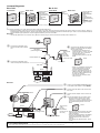
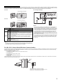
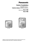
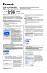
Installation Guide
Network Camera
Model No.
Indoor Use Only
BL-C101
BL-C121
Please read this document before using the product, and save this document for future
reference. Panasonic Network Camera Website:
http://panasonic.net/pcc/products/netwkcam/
(Wired Type)
(Wireless/Wired Type)
This manual is written for both the BL-C101 (Wired Type) and BL-C121 (Wireless/Wired Type). Available features and operations vary slightly
depending on the model. You can confirm the model no. of your camera by checking the model no. printed on the front of the camera.
Model number suffixes (“A”, “CE”, and “E”) are omitted from the following model numbers shown in this document, unless necessary.
BL-C101A, BL-C101CE, BL-C101E, BL-C121A, BL-C121CE, BL-C121E
Please read the included Important Information before proceeding.
Complete Operating Instructions and all other documentation can be found on the included CD-ROM.
• This document (Installation Guide) explains how to physically connect the camera to the power supply and network, as well how to mount or place the
camera for regular use.
• The Setup Guide describes how to set up the camera so that it can be accessed using a PC.
• Refer to the Operating Instructions on the CD-ROM for details regarding the camera’s features.
• Refer to the Troubleshooting Guide on the CD-ROM if you have any problems configuring or using the camera.
Abbreviations
• UPnP is the abbreviation for “Universal Plug and Play”.
• The Network Camera is referred to as “the camera” in this document.
• The Setup CD-ROM is referred to as “the CD-ROM” in this document.
Installation Procedure Overview
The following is an overview of the steps required to install and setup the camera. All steps are explained in this document unless otherwise noted.
Preparation
Camera Diagram
Connections
Setup
Mounting
Confirm that you have all the
items required for installation.
Make sure you know the names
of the camera’s physical
features.
Connecting the camera to your
network and to the power outlet.
Setting up the camera
(described in the included Setup
Guide). This involves configuring
the camera so that it can be
accessed from a PC.
Mounting or placing the camera.
Preparation
1.
Confirm the following items are included in the camera’s packaging.
BL-C101
Main Unit (1 pc.)
The appearance of your
camera depends on which
model you have purchased.
Screw A BL-C101 (6 pcs.)/BL-C121
(4 pcs.)
Order No. XTB4+20AFJ
Used for wall mounting the camera.
Washer S (1 pc.)
Order No. XWG26D12VW
Used when securing the safety
wire to the camera.
AC Adaptor (1 pc.)
Order No. PQLV206Y
Cord Length: About 3 m
(9 feet 10 inches)
BL-C101A/BL-C121A
Screw B (1 pc.)
Order No. XTB26+10GFJ
Used for securing the safety wire to
the camera.
Washer L (1 pc.)
Order No. XWG4F16VW
Used when securing the safety
wire to the wall.
Order No. PQLV216CE1Z
Cord Length: About 3 m
(9 feet 10 inches)
BL-C101CE/BL-C101E/BLC121CE/BL-C121E
Safety Wire (1 pc.)
Order No. PQME10080Z
Used to secure the camera when wall
mounting it.
Flexible Stand (1 pc.)
Order No. PNKL1008Z
Used to attach the camera to the
wall.
AC Cord (1pc. for BLC101CE/BL-C101E/BLC121CE/BL-C121E)
Order No. PFJA02A006Z
Cord Length: About 1.8 m
(5 feet 11 inches)
BL-C101CE/BL-C121CE
Important Information (1 pc.)
Installation Guide
(this document) (1 pc.)
Setup Guide (1 pc.)
Setup CD-ROM (1 pc.)
Order No. PQQX15704MCD
Contains the Setup Program
needed to configure the camera,
as well as the camera’s
documentation.*
BL-C121
Order No. PSJA1106Z
Cord Length: About 1.8 m
(5 feet 11 inches)
BL-C101E/BL-C121E
2.
*See the included Important Information
for a description of each document.
BL-C101 Only
Power Transfer Unit (1 pc.)
Order No. PNWP3C160A
Used to power the camera.
You will need the following additional items to install and configure the camera.
– a PC (see the system requirements in the Important Information document)
– For BL-C101: 2 LAN cables (CAT-5 straight cable)
For BL-C121: a LAN cable (CAT-5 straight cable)
– a router
© Panasonic Communications Co., Ltd. 2008
PNQX1566YA KK0908CM1108
Camera Diagrams
BL-C101
BL-C121
Front View
Rear View
A Indicator*1
B Lens
A C Microphone
Front View
D FACTORY DEFAULT
RESET button
E Serial number label
E F Stand/Tripod Mounting
Hole
F G External INPUT
interface
G H DATA/POWER IN
D
B
C
H
Rear View
A
A Indicator*1
B Lens
C Microphone
B
D
G
E
H
F
I
C
J
K
*1
D FACTORY DEFAULT
RESET button
E WIRELESS/WIRED
switch
F LAN port
G Serial number label
H Stand/Tripod Mounting
Hole
I External I/O interface
J DC IN jack
K Hook for AC adaptor
cord
See 1.1 Understanding the Camera Indicator in the Troubleshooting Guide on the CD-ROM for indicator meaning.
Connections
Connect the camera to your router and to the power outlet as described below.
• Before proceeding, confirm that your PC is connected to your router and can access the Internet. Also confirm that your router’s UPnP™ feature is
enabled. (Most routers have UPnP™ turned off by default.) Refer to the operating instructions included with your router or to the Panasonic Network
Camera website (http://panasonic.net/pcc/support/netwkcam/) for more information.
BL-C101
• Use a LAN cable that is no more than 30 m (98 feet 5 inches) long to connect the camera and the power transfer unit.
1
3
Connect the LAN cable to the
camera and the power transfer
unit.
Connect the AC adaptor to the power
transfer unit and plug the AC adaptor
into the power outlet.
• Confirm that the indicator turns
To the power
green after about 1 minute. If it does
outlet
not turn green, see 1.2 Camera
(For BLIndicator Issues in the
C101CE/
Troubleshooting Guide on the CDROM.
BL-C101E
use an AC cord)
Green
LAN cable
(Cat-5 straight cable)
Power transfer unit
2
AC adaptor
Connect the LAN cable to the
router and the power transfer unit.
LAN cable
• When you operate the camera, the
power outlet should be near the
camera and easily accessible.
• Use only specified Panasonic AC
adaptor (Order No. PQLV206Y for
BL-C101A, PQLV216CE1Z for BLC101CE, BL-C101E).
• The camera may become warm.
This is normal.
Router
Modem
Internet
PC
BL-C121
1
2
WIRELESS/WIRED switch
3
4
Router
WAN
LAN
4
Internet
3
2
1
Modem
PC
LAN cable
(Cat-5 straight cable)
Confirm that the WIRELESS/WIRED switch
on the side of the camera is set to WIRED.
Connect the LAN cable to the camera and
the router.
Connect the AC adaptor cord to the DC IN
jack.
Plug the AC adaptor into the power outlet.
• Confirm that the indicator turns green
after about 1 minute. If it does not turn
green, see 1.2 Camera Indicator Issues in
the Troubleshooting Guide on the CDROM.
Green
To the power
outlet
(For BLC121CE/BLC121E use an • When you operate the camera, the power
AC cord)
outlet should be near the camera and
easily accessible.
• Use only specified Panasonic AC adaptor
(Order No. PQLV206Y for BL-C121A,
AC adaptor
PQLV216CE1Z for BL-C121CE, BLC121E).
• The camera may become warm. This is
normal.
After the camera’s indicator turns green, you may set up the camera. Continue by following the procedure described
in the included Setup Guide.
• If the indicator does not turn green, see 1.2 Camera Indicator Issues in the Troubleshooting Guide on the included CD-ROM.
2
Connecting External I/O interface
The camera’s external I/O interface allows you to connect a device, such as a sensor or motion detector, that can be used to trigger the camera’s image
buffering and transferring features (see Section 2 Using Triggers to Buffer and Transfer Images in the Operating Instructions on the CD-ROM), as well as
the detection notification sound feature (see Section 1.2.7 Detection Notification Sound in the Operating Instructions on the CD-ROM).
BL-C101
Circuit Diagram Example
External INPUT interface
BL-C121 only
Camera
Relay
Light
9 V*
4
3
Door Sensor (Alarm)
2
1
BL-C121
External I/O interface
*DC 8 V–10 V
Terminal
IN
OUT
BL-C121
only
Description
1
GND terminal.
2
External sensor input. The camera can be triggered by either an open
circuit or a GND short-circuit.
3
External device control output. Allows you to control an external device
using the output buttons in the camera’s operation bar (for example,
turning a light on or off).
• This terminal’s behavior can be changed (see 7.4 Controlling the
External Output Terminal (BL-C121 Only) in the Operating Instructions
on the CD-ROM).
• This terminal is an open collector circuit. The maximum drawing
current is the same as terminal 4. Do not exceed the voltage of
terminal 4.
4
DC power output terminal.
• DC 8 V–10 V
• Maximum load is 100 mA.
Caution
• The external I/O interface is not capable of connecting directly to
devices that require large amounts of current. In some cases, a
custom interface circuit (customer-provided) may have to be used.
Serious damage to the camera may result if a device that exceeds
its electrical capability is connected to the external I/O interface.
• Low voltage/current circuits and high voltage/current circuits are
used in the camera circuit. All wiring should be performed by a
qualified electrician. Incorrect wiring could damage the camera and
cause a fatal electric shock.
• External devices connected to the camera’s output terminals cannot
be controlled in the event of a network error or failure. Keep this in
mind when connecting door locks, heat-emitting devices, or other
devices that may be dangerous if they cannot be controlled. (BLC121 only)
Note
• If excessive force is used when disconnecting wires with pointed objects from
the external I/O interface, terminals may become damaged or the interface may
be pushed inside the camera body and become unusable.
For BL-C121: Notes About Wireless Communication
The radio wave range may decrease depending on the surrounding environment or existence of obstacles. If obstacles such as the following are placed
between a camera and a router, radio waves will weaken. Therefore, even if the distance between the camera and router is short, the frame rate may
decrease or images may not be displayed.
• A metallic door or shutter
• A wall with an insulation material that contains aluminum foil
• A wall made of tin
• A wall made of concrete, stone or brick
• Fireproof glass
• Several walls separated by open space
• A steel shelf
In the example below, wireless communication between the camera and the wireless router is impaired due to steel doors or reinforced concrete walls
between the camera and the wireless router.
Wireless antenna is built in the camera.
Position the camera away from obstacles such as
steel doors or reinforced concrete walls.
3
Mounting the Camera
4.
• The camera illustrations in this document depict the BL-C121.
Caution
• Do not drive the screws into a soft material. Drive the screws into a
secure area of the wall, such as a wall stud, otherwise the camera
may fall and be damaged.
• Make sure you attach the safety wire when mounting the camera, to
prevent the camera from falling.
Note
• Use screws that are appropriate for the material of the wall.
• The included screws are for use with wooden walls only.
• The camera is intended for indoor use only and should not be
mounted outdoors.
• To ensure that camera images are displayed properly, do not mount
the camera on an incline. Mount the camera so that it is
perpendicular to the floor. Do not mount the camera upside down.
Loosen the position lock located on the rear side of the flexible stand,
and turn the mounting screw to attach the camera.
N Ceiling
N Wall
Stand/tripod
mounting hole
Position lock
Mounting screw
Stand/tripod
mounting hole
Position lock
Indicator
Mounting screw
5. Adjust the camera position and tighten the position lock.
N Ceiling
N Wall
Position lock
Flexible Stand Mount
1.
2.
3.
Loosen the position lock located on the rear side of the flexible stand.
Turn the mounting screw to attach the camera.
Adjust the angle, then fasten the position lock.
Stand/tripod
mounting hole
Position lock
6.
Connect all necessary cables (AC adaptor, LAN, etc.) to the camera,
dress the cables neatly, and secure with tape (customer-provided).
N Ceiling
N Wall
Tape
(customer-provided)
Tape
(customer-provided)
Mounting screw
Position lock
Flexible stand
Tripod Mount
• Do not use a tripod screw with a thread of 6 mm (1/4 inch) or more.
This may damage the stand/tripod mounting hole.
• The camera cannot be mounted depending on the shape of the
camera platform.
7.
Secure the safety wire to the ceiling or wall using screw A (included)
and washer L (included).
• Leave some slack in the safety wire, as shown.
• Make sure the safety wire is firmly mounted on a wall or ceiling stud (25 mm [1 inch]
and greater) etc. When there is no stud, apply a board on the other side of the ceiling
or wall to make sure the camera does not drop.
N Ceiling
N Wall
Stand/tripod
mounting hole
Washer L
Screw A
Safety wire
Screw A
Tripod
(customer-provided)
When mounting on a mortar or concrete surface
• Prepare anchors for 4 mm (3/16 inch) diameter screws for mounting.
Ceiling/Wall Mount
1.
Washer L
1.
Secure the safety wire to the camera using screw B (included) and
washer S (included).
• Make sure you attach the safety wire when mounting the camera, to prevent the
camera from falling.
2.
Place the flexible stand on the ceiling or wall where you plan to mount
the flexible stand and mark the points where you are going to make
holes.
Make holes with an electric drill. Insert anchors (customer-provided)
into the holes and use a hammer to make them flush with the wall.
• Mortar ceilings or walls break easily when drilling. Be careful of pieces of mortar
which may become loose and fall.
Safety wire
Drill for concrete (in case of tile, use a drill for tile)
Washer S
Screw B
2.
Connect a LAN cable to the camera.
3.
• Insert the LAN cable until it clicks into to place.
For BL-C101 Only: Connecting to the power transfer unit
8.
Mount the flexible stand using the screws.
Connect a LAN cable to the power transfer unit and to the switching
hub, router, etc.
• The power transfer unit can be fixed in place with 2 pieces from screw A (included)
(4 mm x 20 mm [3/16 inch x 13/16 inch]).
3.
LAN Cable
Mount the flexible stand firmly to the ceiling or wall with screw A
(included).
• Do not drive the screws into a soft material. Drive the screws into a secure area of the
wall, such as a wall stud, otherwise the camera may fall and be damaged.
• Use screws that are suited for the type of material the camera is mounted to.
• Allow sufficient space between the ceiling or wall and the flexible stand to turn the
position lock.
• Make sure the flexible stand is firmly mounted on a wall or ceiling stud (25 mm
[1 inch] and greater) etc. When there is no stud, apply a board on the other side of the
ceiling or wall to make sure the camera does not drop.
N Ceiling
N Wall
At least 25 mm
(1 inch)
At least 25 mm
(1 inch)
Screw A (3 pcs.)
Allow sufficient space
between the wall and
the flexible stand
9.
Connect a LAN cable from the camera to the power transfer unit.
10. Connect the AC adaptor to the power transfer unit and plug the other
end into the power outlet.
• The camera will activate.
To the power outlet
(For BL-C101CE/
BL-C101E
use an AC cord)
Allow sufficient space
between the ceiling
and the flexible stand
Screw A
(3 pcs.)
To router
Hook for AC adaptor
4