1
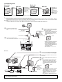
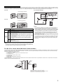
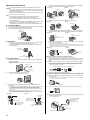
Mounting the Camera
4.
• The camera illustrations in this document depict the BL-C121.
Caution
• Do not drive the screws into a soft material. Drive the screws into a
secure area of the wall, such as a wall stud, otherwise the camera
may fall and be damaged.
• Make sure you attach the safety wire when mounting the camera, to
prevent the camera from falling.
Note
• Use screws that are appropriate for the material of the wall.
• The included screws are for use with wooden walls only.
• The camera is intended for indoor use only and should not be
mounted outdoors.
• To ensure that camera images are displayed properly, do not mount
the camera on an incline. Mount the camera so that it is
perpendicular to the floor. Do not mount the camera upside down.
Loosen the position lock located on the rear side of the flexible stand,
and turn the mounting screw to attach the camera.
N Ceiling
N Wall
Stand/tripod
mounting hole
Position lock
Mounting screw
Stand/tripod
mounting hole
Position lock
Indicator
Mounting screw
5. Adjust the camera position and tighten the position lock.
N Ceiling
N Wall
Position lock
Flexible Stand Mount
1.
2.
3.
Loosen the position lock located on the rear side of the flexible stand.
Turn the mounting screw to attach the camera.
Adjust the angle, then fasten the position lock.
Stand/tripod
mounting hole
Position lock
6.
Connect all necessary cables (AC adaptor, LAN, etc.) to the camera,
dress the cables neatly, and secure with tape (customer-provided).
N Ceiling
N Wall
Tape
(customer-provided)
Tape
(customer-provided)
Mounting screw
Position lock
Flexible stand
Tripod Mount
• Do not use a tripod screw with a thread of 6 mm (1/4 inch) or more.
This may damage the stand/tripod mounting hole.
• The camera cannot be mounted depending on the shape of the
camera platform.
7.
Secure the safety wire to the ceiling or wall using screw A (included)
and washer L (included).
• Leave some slack in the safety wire, as shown.
• Make sure the safety wire is firmly mounted on a wall or ceiling stud (25 mm [1 inch]
and greater) etc. When there is no stud, apply a board on the other side of the ceiling
or wall to make sure the camera does not drop.
N Ceiling
N Wall
Stand/tripod
mounting hole
Washer L
Screw A
Safety wire
Screw A
Tripod
(customer-provided)
When mounting on a mortar or concrete surface
• Prepare anchors for 4 mm (3/16 inch) diameter screws for mounting.
Ceiling/Wall Mount
1.
Washer L
1.
Secure the safety wire to the camera using screw B (included) and
washer S (included).
• Make sure you attach the safety wire when mounting the camera, to prevent the
camera from falling.
2.
Place the flexible stand on the ceiling or wall where you plan to mount
the flexible stand and mark the points where you are going to make
holes.
Make holes with an electric drill. Insert anchors (customer-provided)
into the holes and use a hammer to make them flush with the wall.
• Mortar ceilings or walls break easily when drilling. Be careful of pieces of mortar
which may become loose and fall.
Safety wire
Drill for concrete (in case of tile, use a drill for tile)
Washer S
Screw B
2.
Connect a LAN cable to the camera.
3.
• Insert the LAN cable until it clicks into to place.
For BL-C101 Only: Connecting to the power transfer unit
8.
Mount the flexible stand using the screws.
Connect a LAN cable to the power transfer unit and to the switching
hub, router, etc.
• The power transfer unit can be fixed in place with 2 pieces from screw A (included)
(4 mm x 20 mm [3/16 inch x 13/16 inch]).
3.
LAN Cable
Mount the flexible stand firmly to the ceiling or wall with screw A
(included).
• Do not drive the screws into a soft material. Drive the screws into a secure area of the
wall, such as a wall stud, otherwise the camera may fall and be damaged.
• Use screws that are suited for the type of material the camera is mounted to.
• Allow sufficient space between the ceiling or wall and the flexible stand to turn the
position lock.
• Make sure the flexible stand is firmly mounted on a wall or ceiling stud (25 mm
[1 inch] and greater) etc. When there is no stud, apply a board on the other side of the
ceiling or wall to make sure the camera does not drop.
N Ceiling
N Wall
At least 25 mm
(1 inch)
At least 25 mm
(1 inch)
Screw A (3 pcs.)
Allow sufficient space
between the wall and
the flexible stand
9.
Connect a LAN cable from the camera to the power transfer unit.
10. Connect the AC adaptor to the power transfer unit and plug the other
end into the power outlet.
• The camera will activate.
To the power outlet
(For BL-C101CE/
BL-C101E
use an AC cord)
Allow sufficient space
between the ceiling
and the flexible stand
Screw A
(3 pcs.)
To router
Hook for AC adaptor
4