1
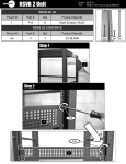
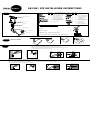
AB1/AB1 HTS INSTALLATION INSTRUCTIONS
Provided fasteners and tools
AB1 HTS
Step 1 I Identify parts
Mounting plate (1)
Screw covers
(1)
(5)
M4 X 10mm Phillips
pan head machine screw
(1)
(5) M5 X 12mm Phillips pan
head machine screw
(2)
(10) #8 X 3/4" Phillips pan
head self-tapping screw
(2)
(10) #8 X 1-3/4'' Phillips pan
head self-tapping screw
(1)
(5) 5/64'' Hex key
AB1 HTS
(2)
(10)
plastic anchor
(1)
(5)
8-32 X 1/2'' Phillips pan
head machine screw
(1)
(5)
Circular nut (PEM)
8-32 thread
(1)
(5)
1/4-20 X 1" Phillips pan
head machine screw
(1)
(2)
3/32'' Drill bit
(1)
(5) 1/4-20 Threaded
Keyhole adapter plug
Knurled side
3/32''
Extension
Additional installation tools
Phillips Head Screw Driver
Adjusting knuckle
Pencil
Mounting plate (2)
Electric Drill
Drill Bits: 1/8'' drill bit for drywall
Speaker plate
1/8''
3/16'' masonry bit for cement wall applications
Ceiling
Wall
Step 2 D Decide on location
Step 3
Installation of wall plate
Mounting to drywall.
1. Use wall plate as a template and mark screw hole locations.
2. Drill into drywall with 1/4'' drill bit. Insert the anchors into hole, see fig. 3.
3. Secure with #8 x 1-3/4'' screws, see fig. 4.
1 3/4"
fig. 2
fig. 3
fig. 4
Mounting to solid concrete or cinder block.
1. Drill into surface with 3/16'' masonry drill bit to 1-3/4" deep. Insert anchors into the holes, see fig. 3.
2. Secure wall plate with #8 x 1-3/4" screws, see fig. 4.
fig. 4
1 3/4"
fig. 2
fig. 3
3/16'' mason bit
Wall
Step 3 In Installation of wall plate (continued)
Mounting to solid wood or wood studs.
Drill a pilot hole into center of each location using 3/32" drill bit (provided).
Drill 1-1/4'' into the stud.
Attach wall plate with two #8 x 1-3/4" wood screws.
Step 4
Installation of radius plate, button stud plate or
mounting plate onto speaker.
1. Speakers with one threaded insert (fig. 1) or Bose® series (fig. 2).
fig. 3
fig. 1
fig. 2
fig. 1
fig. 2
fig. 6
fig. 5
®
#8 x 1-3/4"
fig. 4
wall
wall
wall
Step 5 I
Installation of adjusting knuckle and
extension.
fig. 13
2. Speakers with single keyhole in back. Insert assembly (fig. 3) into
keyhole and slide upward -then tighten (fig. 4).
fig. 3
fig. 4
fig. 14
Set screw location
Screw covers
3. Speakers without mounting holes - wood cabinet only.
Set screw locations
extension
Set screw location
fig. 15
#8 x 3/4''
1/2"
3/32'' drill bit
4. Speakers with 1/4"-20 insert on back.
OmniMount Systems, Inc.
The Pointe at South Mountain
8201 South 48th Street
Phoenix, Arizona 85044-5355
Toll free 1-800-MOUNT-IT
(480) 829-8000
Fax: (480)756-9000
email: [email protected]
100% Replacement Warranty
Audio Basics products are engineered and manufactured to the highest standards. In the event that there are defects in materials,
workmanship, or missing parts, OmniMount Systems will, at its discretion, repair or replace your Audio Basics product. Claims that are
submitted must include either the sales slip or proof of purchase.
If OmniMount products are used for purposes other than their original intent, OmniMount Systems, its distributors and retailers shall not be
held responsible or liable for injuries or property damage, direct, indirect or consequential, which may arise from the inability to use this
product safely, properly, and in the manner for which it has been designed and manufactured.
This warranty does not apply to products which have been lost, damaged by misuse, abuse or accident, altered or repaired in any way other
than specified by OmniMount Systems, Inc.
This warranty is non-transferable.
For installation assistance please call our toll free help line at 1-800-MOUNT-IT
Copyright 2004 OmniMount Systems, Inc. All
rights reserved. OmniMount products are
covered by patents issued and/or pending.
“OmniMount” is a registered trademark of
OmniMount Systems, Inc. "Audio Basics" is a
trademark of OmniMount Systems, Inc.
AB-2 revision 2, 1/04 Part #1000254. Printed
in the U.S.A.