1
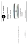
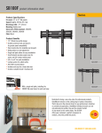
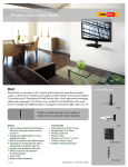
8
P/N 1002342—Rev. B 8/2004
OmniMount Systems, Inc.
8201 South 48th Street • Phoenix, AZ 85044-5355
1-800-MOUNT-IT • www.omnimount.com
Every effort has been made to provide accurate and error-free assembly and installation.
OmniMount Systems disclaims liability for any difficulties arising from the interpretation
of information contained in these instructions. If OmniMount products are used for purposes other than their original intent, OmniMount, its distributors and retailers shall not
be held responsible or liable for injuries or property damage, direct, indirect, or consequential, which may arise from the inability to use this product safely, properly, and in the
manner for which it has been designed and manufactured. Warranty does not apply to
products which have been lost, damaged by misuse, abuse, or accident.
Specifications are subject to change without prior notice.
Warranty: Limited Lifetime on manufacturing defects and workmanship.
Thank you for purchasing an OmniMount product.
Questions? 1-800-MOUNT IT
IMPORTANT: To utilize the PMD projector mount, the projector must have
mounting lands (threaded inserts) on the base. Contact OmniMount if you have any
questions regarding the proper installation of this projector mount system.
User Friendly Adjustments
Adjustable Ceiling Pipe Drop
Superior Mounting Flexibility
Universal Mounting Grid
PMD1 PRO & PMD2 PRO:
Universal Projector Mounts
Installation Instructions
2
1
Pipe Drop Assembly
Plastic Cover
Ceiling Plate
Hex Screw: ¼”-20 X ¼”
Screw: ¼”-20 X 3/8”
C
D
E
F
G
14
1
Lag Bolt: 5/16” X 3”
Plastic Plugs
Hex Wrench
J
K
4
I
4
6
Hex Screw: ¼”-X 5/8”
Hex Screw: ¼”-X ½”
H
1
2
1
1
1
Bottom Projector Plate
B
1
Qty.
A
Description
Mount Assembly Hardware
Top Projector Plate
Part
Models: PMD 1 & PMD 2
(d)
(b)
(e)
(d)
(d)
(d)
(c)
Bag
Fig. 13
7
Proceed to Step 4 to complete the installation.
Position top projector mounting plate into desired orientation
(horizontal or vertical), and then tighten set screw (F).
Thread ¼” hex head set screw (F) into side of pipe collar, on top
projector mounting plate (A). (Fig. 17)
Note: If necessary, screw in tilt knob to gain access to the set
screw hole.
Loosely thread top projector mounting plate (A) onto threaded
portion of wall mount coupler. (Fig. 15 & 16)
Separate top and bottom projector mounting plates (A&B), by
sliding them apart. (Fig. 2)
Install the OmniMount PMD-WM wall mount to the wall as per
the instructions. (Fig. 14)
Fig. 17
Fig. 16
Fig. 15
Fig. 14
Attach cables to the projector. Turn projector ON, and make pitch
and keystone adjustments as per the projector manufacturers
instructions. For additional pitch/tilt, use the three adjustment
knobs on top of the PMD mount (Fig. 13).
Important: Always secure projector plates by installing 3/8”
screws (G) into holes on front edge of plates.
Additional security can be provided by installing small padlocks through security slots at the rear of the projector plates.
(Fig. 12)
Wall Mounting with OmniMount PMD-WM
Fig. 12
Fig. 10
Fig. 9
Fig. 8
6
Note: Make sure that the cables don’t get
pinched while sliding the plates together.
Slide the bottom projector mounting plate onto
the previously installed top projector mounting
plate. (Fig. 11)
Step 5
Fig. 11
Caution: Do not force or over tighten the mounting screws, or damage to the projector
may occur.
Once all mounting screws have been installed, square up the projector mounting plate,
and then tighten the mounting screws securely.
Note: A 1” plastic spacer (3) is included for projectors with
uneven mounting surfaces. Trim the plastic spacer to the
required length, and install on appropriate mounting screw.
Repeat this procedure for the remaining threaded inserts.
(Fig. 10)
Lift the projector mounting plate and place a second large
washer (1) onto the end of the screw, followed by a metal
spacer (2). Loosely thread (2-3 turns) screw assembly into
the chosen threaded insert on the bottom of the projector.
(Fig. 9)
Place a large washer (1) over mounting screw, and then insert screw through grid at marked location. (Fig. 8)
Screw:
4mm x 25mm
Screw:
3mm x 25mm
5
6
Screw:
4mm x 25mm
Screw:
5mm x 25mm
Screw:
6mm x 25mm
PMD-2
4
4
4
1
8
4
Qty.
(c)
(c)
(c)
(b)
(a)
(a)
Bag
Hardware Bags
3
•
•
•
Press plastic cover (D) into place over ceiling plate.
Attach pipe drop assembly (C) to ceiling plate with three 5/8”
hex screws (H).
Note: Orient the cable management port on the pipe drop
assembly so that it faces the projector cable drop.
Standard Ceiling Mount
Note: Orient the cable management port
on the pipe drop assembly so that it faces
the projector cable drop.
Pipe extension should be cut to the required
additional length, threaded on both ends,
and then attached to the standard pipe drop
assembly with a pipe coupler (not supplied).
For installations that require a ceiling drop
in excess of 18”, standard 1 ½” pipe may be
used to extend the standard pipe drop assembly.
Extended Ceiling Mount
Wall Mount
Flush Mount
Extended Ceiling Mount
Determine type of installation:
• Standard Ceiling Mount
Step 2
With an electronic stud finder, locate center of ceiling stud in desired mounting location. Unscrew ceiling plate (E) from Projector Mounting top plate (A). Use ceiling plate
as a template, and mark mounting hole locations. Drill mounting holes to a depth of 3”
using a 3/16” drill bit. Mount ceiling plate to stud with 5/16” lag bolts (J).
Step 1
Screw:
5mm x 25mm
PMD-1
Plastic Spacer: 1”
Projector Mounting Hardware
Large Washer
Metal Spacer: 3/8”
4
3
1
2
Part
Separate top and bottom projector mounting plates
(A&B), by sliding them apart. (Fig. 2)
Fig. 1
4
Note: If necessary, screw in tilt knob to gain access to
the set screw hole.
Fig. 3
Thread ¼” hex head set screw (F) into side of pipe collar, on top projector mounting
plate (A). (Fig. 3)
Fig. 2
Secure the pipe position by installing ½” long hex
screws (I) into adjustment screw holes. For a cleaner
appearance, insert plastic plugs (K) into unused
holes on extension tube.
Gently pull the extension tube of the pipe drop assembly down to the required projector height. Rotate
extension tube so that adjustment screw holes are
visible through the support tube. (Fig. 1)
Step 3
With the addition of the OmniMount PMD-WM wall
mount (sold separately); the PMD can be mounted to a
wall instead of the ceiling. This is particularly useful for
small conference/classrooms where a ceiling mount is
impractical. For details, see section at end of manual,
titled Wall Mounting with OmniMount PMD-WM.
Wall Mount
Proceed to step 3.
Note: Plastic cover is not used for flush mount.
Flush Ceiling Mount
Fig. 5
Fig. 4
5
Fig. 6
Fig. 7
Using a pencil or felt tipped pen, mark the locations of the
projectors threaded inserts onto the grid for reference.
(Fig. 7)
Lay projector on table with mounting surface face up. Place
grid section of bottom projector mounting plate onto top of
projector in desired mounting orientation (horizontal or vertical). (Fig. 6)
Determine required mounting screw size (4, 5 or 6 mm) for projector.
Note: Consult projectors owners’ manual for screw sizes and mounting holes.
Step 4
For flush ceiling mount, loosely thread top projector
mounting plate directly onto threaded portion of ceiling
plate.
Flush Ceiling Mount
Thread cable bundle through cable management port at top of
pipe assembly, down through the pipe assembly, and then out
through the cable management port on the rear of the projector
mounting plate. (Fig. 5) (Standard ceiling mount only) Be sure
to leave enough cable to reach the mounted projector.
Position top projector mounting plate into desired orientation
(horizontal or vertical), and then tighten set screw (F). (Fig. 4)
Loosely thread top projector mounting plate (A) onto threaded
portion of pipe drop.