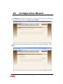
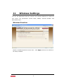
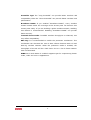
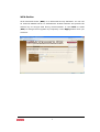
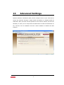
1
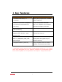
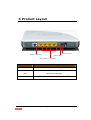
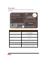
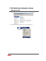
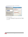
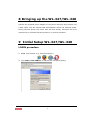
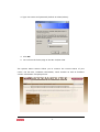
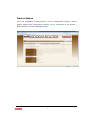
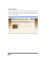
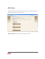
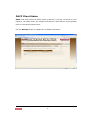
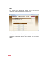
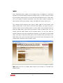
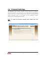
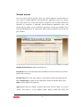
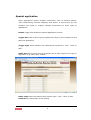
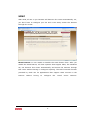
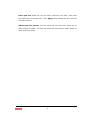
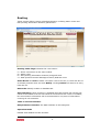
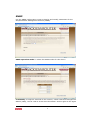
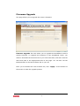
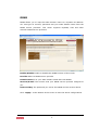
WL-347/WL-348 Wireless Broadband modem/router (ADSL2+, 802.11B/G/N draft 2.0) User Manual Version: 1.0 2 TABLE OF CONTENTS 1 KEY FEATURES ...................................................................................................................... 5 2 PACKAGE CONTENTS ......................................................................................................... 6 3 PRODUCT LAYOUT .............................................................................................................. 7 4 NETWORK + SYSTEM REQUIREMENTS ................................................................... 9 5 WL-347/WL-348 PLACEMENT...................................................................................... 9 6 SETUP LAN, WAN............................................................................................................... 10 7 PC NETWORK ADAPTER SETUP (WINDOWS XP) .............................................11 8 BRINGING UP THE WL-347/WL-348 ..................................................................... 13 9 INITIAL SETUP WL-347/WL-348 ............................................................................ 13 10 CONFIGURATION WIZARD...................................................................................... 22 11 WIRELESS SETTINGS ................................................................................................. 24 12 FIREWALL SETTINGS ................................................................................................. 35 13 ADVANCED SETTINGS................................................................................................ 41 14 TOOLBOX SETTINGS ................................................................................................... 53 3 Introduction Congratulations on your purchase of the WL-347/WL-348 Wireless Network Broadband modem/Router. The WL-347/WL-348 is compliant with draft 802.11n v 2.0 and up to 6 times faster than standard 802.11g based routers while still being compatible with 802.11g & 802.11b gadgets. The WL347/WL-348 is not only a Modem or Wireless Access Point, but also doubles as a 4-port full-duplex Switch that connects your wired-Ethernet devices together at. At 300 Mbps wireless transmission rate, the Access Point built into the Modem/Router uses advanced MIMO (Multi-Input, Multi-Output) technology to transmit multiple steams of data in a single wireless channel, giving you seamless access to multimedia content. Robust RF signal travels farther, eliminates dead spots and extends network range. For data protection and privacy, the WL-347/WL-348 encodes all wireless transmissions with WEP, WPA, and WPA2 encryption. With an inbuilt DHCP Server & powerful SPI firewall the WL-347/WL-348 protects your computers against intruders and most known Internet attacks but provides safe VPN pass-through. With the incredible speed and QoS function of 802.11n(draft2.0), the WL-347/WL-348 is ideal for media-centric applications like streaming video, gaming, and VoIP telephony to run multiple media-intense data streams through the network at the same time, with no degradation in performance. 4 1 Key Features Features Advantages Incredible Data Rate up to Heavy data payloads such as MPEG 300Mbps** video streaming IEEE 802.11n draft 2.0 Compliant Fully Interoperable with IEEE and backward compatible with 802.11b / IEEE802.11g compliant 802.11b/g devices with legacy protection Four 10/100 Mbps Fast Switch Ports Scalability, extend your network. (Auto-Crossover) Firewall supports Virtual Server Avoids the attacks of Hackers or Mapping, DMZ, IP Filter, ICMP Viruses from Internet Blocking, SPI Support 802.1x authenticator, Provide mutual authentication (Client 802.11i (WPA/WPA2, AES), VPN and dynamic encryption keys to pass-through enhance security Integrated modem (Annex A) Fully compatible with the fastest ADSL2+ connections up-to-date. ** Theoretical wireless signal rate based on IEEE standard of 802.11a, b, g, n chipset used. Actual throughput may vary. Network conditions and environmental factors lower actual throughput rate. All specifications are subject to change without notice. 5 2 Package Contents Open the package carefully, and make sure that none of the items listed below are missing. Do not discard the packing materials, in case of return; the unit must be shipped back in its original package. 1. WL-347/WL-348 modem/router 2. 220V ~ 240V Power Adapter 3. Quick Install Guide 4. CD (User’s Manual) 5. Warranty card 6. UTP cable 6 3 Product Layout Power connector Modem connection Reset button LAN / computer connections Port Description ADSL Connect your telephone/ADSL cable this port Connect the cable from your PC’s or network LAN devices to this port Power connector Blinks on traffic for specific LAN PORT 7 Front panel The front panel describes the corresponding LED indications and port functionality. LED Description POWER Lights up when powered ON. Blinks on TEST/RESET Wan Lights up when an ADSL cable is connected. Online Lights up when internet connection is UP. WLAN Lights up in Blue when WLAN is enabled. Blinks on traffic WPS Blinks when WPS mode is on Lan1 - Lan4 When a lan cable is connected the corresponding light lights up. 8 4 Network + System Requirements To begin using the WL-347/WL-348, make sure you meet the following as minimum requirements: • PC/Notebook. • Operating System – Microsoft Windows XP/2000/VISTA • 1 Free Ethernet port. • Wi-Fi card/USB dongle (802.11 b/g/n) – optional. • Annex A, ADSL internet connection. • PC with a Web-Browser (Internet Explorer, Safari, Firefox, Opera) • Ethernet compatible CAT5 cables. 5 WL-347/WL-348 Placement You can place the WL-347/WL-348 on a desk or other flat surface, or you can mount it on a wall. For optimal performance, place your Wireless Broadband Modem/Router in the center of your office (or your home) in a location that is away from any potential source of interference, such as a metal wall or microwave oven. This location must be close to a power connection and the ADSL/phone line should not be over 2 meters long. 9 6 Setup LAN, WAN Modem connection LAN / computer connections 10 7 PC Network Adapter setup (Windows XP) • Enter [Start Menu] select [Control panel] select [Network]. • Select [Local Area Connection]) icon=>select [properties] 11 • Select [Internet Protocol (TCP/IP)] =>Click [Properties]. • Select the [General] tab. a. WL-347/WL-348 supports [DHCP] function, please select both [Obtain an IP address automatically] and automatically]. 12 [Obtain DNS server address 8 Bringing up the WL-347/WL-348 Connect the supplied power-adapter to the power inlet port and connect it to a wall outlet. The WL-347/WL-348 automatically enters the self-test phase. During self-test phase, the Power LED will blink briefly, and then will be lit continuously to indicate that this product is in normal operation. 9 Initial Setup WL-347/WL-348 LOGIN procedure 2. OPEN your browser (e.g. Internet Explorer). 3. Type http://192.168.0.1 in address bar and press [Enter] 13 4. Type user name and password (default is admin/admin). 4. Click OK. 5. You will see the home page of the WL-347/WL-348. The System status section allows you to monitor the current status of your router: the UP time, hardware information, serial number as well as firmware version information is displayed here. 14 LAN settings The LAN tab gives you the opportunity to change the IP settings of the WL347/WL-348. Click <Apply> at the bottom of this screen to save any changes. IP address 192.168.0.1. It is the router’s LAN IP address (Your LAN clients default gateway IP address). IP Subnet Mask 255.255.255.0 Specify a Subnet Mask for your LAN segment. 802.1d Spanning Tree is Disabled by default. If the 802.1d Spanning Tree function is enabled, this router will use the spanning tree protocol to prevent network loops. DHCP Server Enabled by default. You can enable or disable the DHCP server. When DHCP is disabled no ip-addresses are assigned to clients and you have to use static ip-addresses. When DHCP server is enabled your computers will be assigned an ip-address automatically until the lease time expires. 15 Lease Time Forever. In the Lease Time setting you can specify the time period that the DHCP lends an IP address to your LAN clients. The DHCP will change your LAN client’s IP address when this time threshold period is reached. IP Address Pool You can select a particular IP address range for your DHCP server to issue IP addresses to your LAN Clients. Note: default IP range 192.168.0.100 192.168.0.199. If you want your PC(s) to have a static/fixed IP address, then you’ll have to choose an IP address outside this IP address Pool Domain Name You can specify a Domain Name for your LAN. Or just keep the default (SitecomWLxxx). 16 Device Status View the Broadband modem/router’s current configuration settings. Device Status displays the configuration settings you’ve configured in the Wizard / Basic Settings / Wireless Settings section. 17 Internet Status This page displays whether the ADSL port is connected to an ADSL service provider. It also displays the router’s WAN IP address, Subnet Mask, and ISP Gateway as well as MAC address, the Primary DNS. Press Renew button to renew your WAN IP address. 18 ADSL Status This page shows the current operation mode, status of your ADSL connection, the data rate and the quality of your ADSL link. Operation mode allows manual selection of the ADSL mode. 19 DHCP Client Status DHCP This page shows all DHCP clients (LAN PCs) currently connected to your network. The table shows the assigned IP address, MAC address and expiration time for each DHCP leased client. Use the Refresh button to update the available information. 20 WL-347/WL-348 Log View the operation log of the WL-347/WL-348. This page shows the current system log of the Broadband modem/router. It displays any event occurred after system start up. At the bottom of the page, the system log can be saved <Save> to a local file for further processing or the system log can be cleared <Clear> or it can be refreshed <Refresh> to get the most updated information. When the system is powered down, the system log will disappear if not saved to a local file. 21 10 Configuration Wizard Click Wizard to configure the modem. The Setup wizard will now be displayed; check that the adsl line is connected and click Next. Select your country from the Country list. Select your internet provider. Click Next. 22 Depending on the chosen provider, you may need to enter your user name and password or hostname in the following window. After you have entered the correct information, click Next. Click APPLY to complete the configuration. 23 11 Wireless Settings You can set parameters that are used for the wireless stations to connect to this router. The parameters include Mode, ESSID, Channel Number and Associated Client. Wireless Function Enable or Disable Wireless function here. Click Apply and wait for module to be ready & loaded. 24 Basic Settings Band Allows you to set the AP fixed at 802.11b or 802.11g mode. You can also select B+G+N mode to allow 802.11b, 802.11g and 802.11n clients at the same time. ESSID This is the name of the wireless signal which is broadcasted. All the devices in the same wireless LAN should have the same ESSID. Channel Number The channel used by the wireless LAN. All devices in the same wireless LAN should use the same channel. Channel bandwidth 20/40 MHz Allows automatic detection of the operation bandwidth between 20 and 40 MHz. Extension channel This is the optional channel for use. Setting the Bandwidth to 20/40 MHz allows you to use this extension channel as the secondary channel for doubling the bandwidth of your wireless network. 25 Advanced Settings This tab allows you to set the advanced wireless options. The options included are Authentication Type, Fragment Threshold, RTS Threshold, Beacon Interval, and Preamble Type. You should not change these parameters unless you know what effect the changes will have on the router. Fragment Threshold "Fragment Threshold" specifies the maximum size of a packet during the fragmentation of data to be transmitted. If you set this value too low, it will result in bad performance. RTS Threshold When the packet size is smaller then the RTS threshold, the wireless router will not use the RTS/CTS mechanism to send this packet. Beacon Interval is the interval of time that this wireless router broadcasts a beacon. A Beacon is used to synchronize the wireless network. DTIM period is a countdown mechanism for WLAN Access Points changing this value will affect your wireless performance and may improve stability. 26 Preamble Type The “Long Preamble” can provide better wireless LAN compatibility while the “Short Preamble” can provide better wireless LAN performance. Broadcast ESSID If you enabled “Broadcast ESSID”, every wireless station located within the coverage of this access point can discover this access point easily. If you are building a public wireless network, enabling this feature is recommended. Disabling “Broadcast ESSID” can provide better security. Transmit burst mode if enabled wireless throughput is enhanced, this may affect compatibility. 802.11g: It is recommended to enable the protection mechanism. This mechanism can decrease the rate of data collision between 802.11b and 802.11g wireless stations. When the protection mode is enabled, the throughput of the AP will be a little lower due to a lot of frame-network that is transmitted. WMM Wi-Fi Multi Media if enabled supports QoS for experiencing better audio, video and voice in applications. 27 Security This Access Point provides complete wireless LAN security functions, included are WEP, IEEE 802.11x, IEEE 802.11x with WEP, WPA with pre-shared key and WPA with RADIUS. With these security functions, you can prevent your wireless LAN from illegal access. Please make sure your wireless stations use the same security function, and are setup with the same security key. Disable When you choose to disable encryption, it is very insecure to operate the WL347/WL-348. 28 WEP When you select 64-bit or 128-bit WEP key, you have to enter WEP keys to encrypt data. You can generate the key by yourself and enter it. You can enter four WEP keys and select one of them as a default key. Then the router can receive any packets encrypted by one of the four keys. Key Length You can select the WEP key length for encryption, 64-bit or 128bit. The larger the key will be the higher level of security is used, but the throughput will be lower. Key Format You may select ASCII Characters (alphanumeric format) or Hexadecimal Digits (in the "A-F", "a-f" and "0-9" range) to be the WEP Key. Key1 - Key4 The WEP keys are used to encrypt data transmitted in the wireless network. Use the following rules to setup a WEP key on the device. 64-bit WEP: input 10-digits Hex values (in the "A-F", "a-f" and "0-9" range) or 5-digit ASCII character as the encryption keys. 128-bit WEP: input 26-digit Hex values (in the "A-F", "a-f" and "0-9" range) or 13-digit ASCII characters as the encryption keys. 29 Click <Apply> at the bottom of the screen to save the above configurations. You can now configure other sections by choosing Continue, or choose Apply to apply the settings and reboot the device. WPA Pre-shared Key Wi-Fi Protected Access (WPA) is an advanced security standard. You can use a pre-shared key to authenticate wireless stations and encrypt data during communication. It uses TKIP or CCMP (AES) to change the encryption key frequently. So the encryption key is not easy to be cracked by hackers. This is the best security available. 30 WPA-Radius Wi-Fi Protected Access (WPA) is an advanced security standard. You can use an external RADIUS server to authenticate wireless stations and provide the session key to encrypt data during communication. It uses TKIP or CCMP (AES) to change the encryption key frequently. Press Apply button when you are done. 31 ACL This wireless router supports MAC Address Control, which prevents unauthorized clients from accessing your wireless network. Enable wireless access control Enables the wireless access control function Adding an address into the list Enter the "MAC Address” of the wireless station to be added and then click "Apply". The wireless station will now be added. If you are having any difficulties filling in the fields, just clear the MAC Address. 32 WPS Wi-Fi Protected Setup (WPS) is the simplest way to establish a connection between the wireless clients and the wireless router. You don’t have to select the encryption mode and fill in a long encryption passphrase every time when you try to setup a wireless connection. You only need to press a button on both wireless client and wireless router, and WPS will do the rest for you. The wireless router supports two types of WPS: WPS via Push Button and WPS via PIN code. If you want to use the Push Button, you have to push a specific button on the wireless client or in the utility of the wireless client to start the WPS mode, and switch the wireless router to WPS mode. You can simply push the WPS button of the wireless router, or click the ‘Start to Process’ button in the web configuration interface. If you want to use the PIN code, you have to know the PIN code of the wireless client and switch it to WPS mode, then fill-in the PIN code of the wireless client through the web configuration interface of the wireless router. WPS Check the box to enable WPS function and uncheck it to disable the WPS function. 33 WPS Current Status If the wireless security (encryption) function of this wireless router is properly set, you’ll see a ‘Configured’ message here. Otherwise, you’ll see ‘UnConfigured’. Self Pin Code This is the WPS PIN code of the wireless router. You may need this information when connecting to other WPS-enabled wireless devices. SSID This is the network broadcast name (SSID) of the router. Authentication Mode It shows the active authentication mode for the wireless connection. Passphrase Key It shows the passphrase key that is randomly generated by the wireless router during the WPS process. You may need this information when using a device which doesn’t support WPS. WPS via Push Button Press the button to start the WPS process. The router will wait for the WPS request from the wireless devices within 2 minutes. WPS via PIN You can fill-in the PIN code of the wireless device and press the button to start the WPS process. The router will wait for the WPS request from the wireless device within 2 minutes. 34 12 Firewall Settings The Broadband router provides extensive firewall protection by restricting connection parameters, thus limiting the risk of hacker attacks, and defending against a wide array of common Internet attacks. However, for applications that require unrestricted access to the Internet, you can configure a specific client/server as a Demilitarized Zone (DMZ). Note: To enable the Firewall settings select Enable and click Apply. 35 DMZ If you have a client PC that cannot run an Internet application (e.g. Games) properly from behind the NAT firewall, then you can open up the firewall restrictions to unrestricted two-way Internet access by defining a DMZ Host. The DMZ function allows you to re-direct all packets going to your WAN port IP address to a particular IP address in your LAN. The difference between the virtual server and the DMZ function is that the virtual server re-directs a particular service/Internet application (e.g. FTP, websites) to a particular LAN client/server, whereas DMZ re-directs all packets (regardless of services) going to your WAN IP address to a particular LAN client/server. Enable DMZ Enable/disable DMZ Public IP Address The IP address of the WAN port or any other Public IP addresses given to you by your ISP Client PC IP Address Fill in the IP address of a particular host in your LAN that will receive all the packets originally going to the WAN port/Public IP address above. Click <Apply> at the bottom of the screen to save the above configurations. 36 Denial of Service (DoS) The Broadband router's firewall can block common hacker attacks, including Denial of Service, Ping of Death, Port Scan and Sync Flood. If Internet attacks occur the router can log the events. SPI and Anti-Dos firewall protection blocks basic hacker attacks (DOS, Sync flood, port scan) RIP defect Discard Ping to WAN interface The router’s WAN port will not respond to any Ping requests Stateful packet inspection allows the user to manually determine which packets should be scanned. When hackers attempt to enter your network, we can alert you by eMail Enter your email address. Specify your SMTP and POP3 servers, user name and password. Connection Policy Enter the appropriate values for TCP/UDP sessions as described in the following table. 37 Access You can restrict users from accessing certain Internet applications/services (e.g. Internet websites, email, FTP etc.). Access Control allows users to define the traffic type permitted in your LAN. You can control which PC client can have access to these services. Deny If you select “Deny” then all clients will be allowed to access Internet accept for the clients in the list below. Allow If you select “Allow” then all clients will be denied to access Internet accept for the PCs in the list below. Filter client PCs by IP Fill in “IP Filtering Table” to filter PC clients by IP. Add PC You can click Add PC to add an access control rule for users by IP addresses. Remove PC If you want to remove some PCs from the "IP Filtering Table", select the PC you want to remove in the table and then click “Delete Selected". If you want to remove all PCs from the table, just click the "Delete All" button. 38 Filter client PC by MAC Check “Enable MAC Filtering” to enable MAC Filtering. Add PC Fill in “Client PC MAC Address” and “Comment” of the PC that is allowed to access the Internet, and then click “Add”. If you find any typo before adding it and want to retype again, just click "Reset" and the fields will be cleared. Remove PC If you want to remove some PC from the "MAC Filtering Table", select the PC you want to remove in the table and then click "Delete Selected". If you want to remove all PCs from the table, just click the "Delete All" button. If you want to clear the selection and re-select again, just click “Reset”. Click <Apply> at the bottom of the screen to save the above configuration. 39 URL block You can block access to some Web sites from particular PCs by entering a full URL address or just keywords of the Web site. Enable URL Blocking Enable/disable URL Blocking Add URL Keyword Fill in “URL/Keyword” and then click “Add”. You can enter the full URL address or the keyword of the web site you want to block. Remove URL Keyword If you want to remove some URL keywords from the "Current URL Blocking Table", select the URL keyword you want to remove in the table and then click "Delete Selected". If you want remove all URL keywords from the table, just click "Delete All" button. If you want to clear the selection and re-select again, just click “Reset”. Click <Apply> at the bottom of the screen to save the above configurations 40 13 Advanced Settings Network Address Translation (NAT) allows multiple users at your local site to access the Internet through a single Public IP Address or multiple Public IP Addresses. NAT provides Firewall protection from hacker attacks and has the flexibility to allow you to map Private IP Addresses to Public IP Addresses for key services such as Websites and FTP. Select Disable to disable the NAT function. 41 Virtual server Use the Virtual Server function when you want different servers/clients in your LAN to handle different service/Internet application type (e.g. Email, FTP, Web server etc.) from the Internet. Computers use numbers called port numbers to recognize a particular service/Internet application type. The Virtual Server allows you to re-direct a particular service port number (from the Internet/WAN Port) to a particular LAN private IP address and its service port number. Enable Virtual Server Enable Virtual Server. Private IP This is the LAN client/host IP address that the Public Port number packet will be sent to. Private Port This is the port number (of the above Private IP host) that the below Public Port number will be changed to when the packet enters your LAN (to the LAN Server/Client IP) Type Select the port number protocol type (TCP, UDP or both). If you are unsure, then leave it to the default “both” setting. Public Port Enter the 42 service (service/Internet application) port number from the Internet that will be re-directed to the above Private IP address host in your LAN Comment The description of this setting. Add Virtual Server Fill in the "Private IP", "Private Port", "Type", “Public Port” and "Comment" of the setting to be added and then click "Add". Then this Virtual Server setting will be added into the "Current Virtual Server Table" below. Remove Virtual Server If you want to remove Virtual Server settings from the "Current Virtual Server Table", select the Virtual Server settings you want to remove in the table and then click "Delete Selected". If you want to remove all Virtual Server settings from the table, just click the "Delete All" button. Click "Reset" will clear your current selections. Click <Apply> at the bottom of the screen to save the above configurations. 43 Special application Some applications require multiple connections, such as Internet games, video Conferencing, Internet telephony and others. In this section you can configure the router to support multiple connections for these types of applications. Enable Trigger Port Enable the Special Application function. Trigger Port This is the out going (Outbound) range of port numbers for this particular application. Trigger Type Select whether the outbound port protocol is “TCP”, “UDP” or both. Public Port Enter the In-coming (Inbound) port or port range for this type of application (e.g. 2300-2400, 47624) Public Type Select the Inbound port protocol type: “TCP”, “UDP” or both Comment The description of this setting. 44 Popular applications This section lists the more popular applications that require multiple connections. Select an application from the Popular Applications selection. Once you have selected an application, select a location (1-10) in the Copy to selection box and then click the Copy to button. This will automatically list the Public Ports required for this popular application in the location (1-10) you specified. Add Special Application Fill in the "Trigger Port", "Trigger Type”, “Public Port”, "Public Type", "Public Port" and "Comment" of the setting to be added and then click "Add". The Special Application setting will be added into the "Current Trigger-Port Table" below. If you happen to make a mistake, just click "Clear" and the fields will be cleared. Remove If you want to remove Special Application settings from the "Current Trigger-Port Table", select the Special Application settings you want to remove in the table and then click "Delete Selected". If you want remove all Special Application settings from the table, just click the "Delete All" button. Click "Reset" will clear your current selections. 45 UPNP With UPnP, all PCs in you Intranet will discover this router automatically. So, you don’t have to configure your PC and it can easily access the Internet through this router. UPnP Feature You can enable or Disable the UPnP feature here. After you enable the UPnP feature, all client systems that support UPnP, like Windows XP, can discover this router automatically and access the Internet through this router without having to configure anything. The NAT Traversal function provided by UPnP can let applications that support UPnP connect to the internet without having to configure 46 the virtual server sections. QoS QoS can let you classify Internet application traffic by source/destination IP address and port number. You can assign priority for each type of application and reserve bandwidth for it. The packets of applications with higher priority will always go first. Lower priority applications will get bandwidth after higher priority applications get enough bandwidth. This can let you have a better experience in using critical real time services like Internet phone, video conference …etc. All the applications not specified by you are classified as rule name “Others”. The rule with a smaller priority number has a higher priority; the rule with a larger priority number has a lower priority. You can adjust the priority of the rules by moving them up or down. Enable/Disable QoS You can check “Enable QoS” to enable QoS functionality for the WAN port. Traffic mapping Click “Add traffic class” then enter a form of the QoS rule. Click “Apply” after filling out the form the rule will be added into the table. 47 Edit a QoS rule Select the rule you want to edit and click “Edit”, then enter the detail form of the QoS rule. Click “Apply” after editing the form and the rule will be saved. Adjust QoS rule priority You can select the rule and click “Move Up” to make its priority higher. You also can select the rule and click “Move Down” to make its priority lower. 48 Routing These screens define routing related parameters, including static routes and RIP (Routing Information Protocol) parameters. Routing Table Flags Indicates the route status: C = Direct connection on the same subnet. S = Static route. R = RIP (Routing Information Protocol) assigned route. I = ICMP (Internet Control Message Protocol) Redirect route. Static Route Click Add to add a new static route to the list, or check the box of an already entered route and click Modify. Clicking Delete will remove an entry from the list. RIP mode Globally enables or disables RIP. Auto summary If Auto summary is disabled then RIP packets will include subnetwork information from all sub-networks connected to the router. If enabled, this sub-network information will be summarized to one piece of information covering all sub-networks. Table of current Interface RIP parameter Interface The WAN interface to be configured. Operation Mode Disable: RIP disabled on this interface. 49 Enable: RIP enabled on this interface. Silent: Listens for route broadcasts and updates its route table. It does not participate in sending route broadcasts. Version Sets the RIP (Routing Information Protocol) version to use on this interface. 50 SNMP Use the SNMP configuration screen to display and modify parameters for the Simple Network Management Protocol (SNMP). SNMP operation mode To select the SNMP modes for this device. Community A computer attached to the network, called a Network Management Station (NMS), can be used to access this information. Access rights to the agent 51 are controlled by community strings. To communicate with the Router, the NMS must first submit a valid community string for authentication. Note: Up to five community names may be entered. Trap Specify the IP address of the NMS to notify when a significant event is detected by the agent. When a trap condition occurs, the SNMP agent sends an SNMP trap message to any NMS specified as a trap receiver. IP Address Traps are sent to this address when errors or specific events occur on the network. Community A community string (password) specified for trap management. Enter a word, something other than public or private, to prevent unauthorized individuals from accessing information on your system. Version Sets the trap status to disabled, or enabled with V1 or V2c. The v2c protocol was proposed in late 1995 and includes enhancements to v1 that are universally accepted. These include a get-bulk command to reduce network management traffic when retrieving a sequence of MIB variables, and a more elaborate set of error codes for improved reporting to a Network Management Station. 52 14 TOOLBOX Settings Password change options You can change the password required to log into the broadband router's system web-based management. By default, the password is: admin. Passwords can contain 0 to 12 alphanumeric characters, and are case sensitive. Current Password Fill in the current password to allow changing to a new password. New Password Enter your new password Confirmed Password Enter your new password again for verification purposes Click <Apply> at the bottom of the screen to save the above configurations 53 Time Zone The Time Zone allows your router to base its time on the settings configured here, which will affect functions such as Log entries and Firewall settings. Set Time Zone Select the time zone of the country you are currently in. The router will set its time based on your selection. Time Server Address You can set an NTP server address. Enable Daylight Savings The router can also take Daylight savings into account. If you wish to use this function, you must check/tick the enable box to enable your daylight saving configuration (below). Start Daylight Savings Time Select the period in which you wish to start daylight Savings Time End Daylight Savings Time Select the period in which you wish to end daylight Savings Time Click <Apply> at the bottom of the screen to save the above configurations. 54 Remote Management The remote management function allows you to designate a host in the Internet the ability to configure the Broadband router from a remote site. Enter the designated host IP Address in the Host IP Address field. Host Address This is the IP address of the host in the Internet that will have management/configuration access to the Broadband router from a remote site. If the Host Address is left 0.0.0.0 this means anyone can access the router’s web-based configuration from a remote location, providing they know the password. Port The port number of the remote management web interface. Enabled Select “Enabled” to enable the remote management function. Click <Apply> at the bottom of the screen to save the above configurations. 55 Firmware Upgrade This page allows you to upgrade the router’s firmware. Firmware Upgrade This tool allows you to upgrade the Broadband router’s system firmware. To upgrade the firmware of your Broadband router, you need to download the firmware file to your local hard disk, and enter that file name and path in the appropriate field on this page. You can also use the Browse button to find the firmware file on your PC. Once you’ve selected the new firmware file, click <Apply> at the bottom of the screen to start the upgrade process 56 Backup Settings The Backup screen allows you to save (Backup) the router’s current configuration settings. When you save the configuration setting (Backup) you can re-load the saved configuration into the router through the Restore selection. If extreme problems occur you can use the Restore to Factory Defaults selection, this will set all configurations to its original default settings (e.g. when you first purchased the router). Use the "Backup" tool to save the Broadband router current configuration to a file named "config.bin" on your PC. You can then use the "Restore" tool to restore the saved configuration to the Broadband router. Alternatively, you can use the "Restore to Factory Defaults" tool to force the Broadband router to perform a power reset and restore the original factory settings. 57 Reset You can reset the router’s system should any problem exist. The reset function essentially re-boots your router’s system. 58 DDNS DDNS allows you to map the static domain name to a dynamic IP address. You must get an account, password and your static domain name from the DDNS service providers. This router supports DynDNS, TZO and other common DDNS service providers. Enable/Disable Enable or disable the DDNS function of this router Provider Select a DDNS service provider Domain name Fill in your static domain name that uses DDNS Account/E-mail The account that your DDNS service provider assigned to you Password/Key The password you set for the DDNS service account above Click <Apply> at the bottom of the screen to save the above configurations. 59