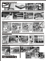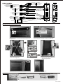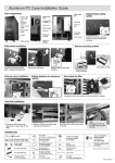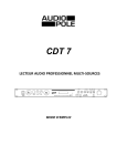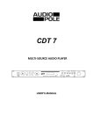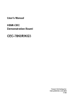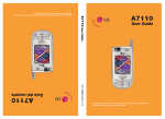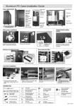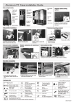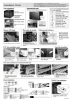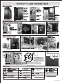
1
5.25" to 3.5"
convertor
3-speed fan
controller
Front door
with lock
SATA hot swap
raid
Door key is attach to
the accessory box
2
1
Remove the plastic slices for
water tube openings.
Push to release
3-speed fan adjustable
device
3
for SSI CEB/EEB
1
The oval hole on M/B tray
designed for special server
boards, please use nut to
hold the copper bolt in place.
2
Loosing two thumb screws to release the M/B tray.
Secure the stand-off bolts on the M/B
tray which match with the M/B fix points,
place the M/B on the copper bolt, fasten
the screws to secure.
Hardware list
Screw(30)
for fix HDD
Mounting bracket
for SSI CEB/EEB M/B
Thumb screw(14)
& rubber ring(14)
for fix HDD
5
Thumb screw(3)
for HDD extra fixing
Thumb screw(7)
for PCI card holder
Aluminum HDD rail(7)
PCI card holder-S(3)
PCI card holder-L(4)
PSU tray(1)
C50.A7110.00E-1
Hard disk installation for SATA HDD cage
OPEN
LOCK
Hard disk installation for modularized HDD cage
1. Fasten the HDD screws with
anti-vibration rubber rings to the
HDD.
2. Slide the HDD into the HDD cage
with the anti-vibration kit.
Press down the HDD into the slots
to secure.
Note:
Adding extra screw to
the HDD cage for extra
security.
PSU installation
Multi-Position HDD Module
Remove HDD module
To the bottom of the case
Loosing four screws remove the
HDD module
In the 5.25" rack
Remove four screws at the base
of the case to release the PSU
stand PSU stand before install
the HDD module.
Change fan
direction
Also can fit on 5.25" rack tray
VGA Card Pillar Installation Guide
1
2
3
4
REAR
C50.A7110.00E-2
AC'97
Black(AGND)
NC
Yellow(R-RET)
KEY
Blue(L-RET)
9
7 Black(GND)
5 Green
3 White
1 Red
KEY10
Black(GND) 8
Green 6
White 4
Red 2
9
7 Black(GND)
5 Green
3 White
1 Red
EAR
MIC
USB
KEY 10
Black(GND) 8
Green 6
White 4
Red 2
HD AUDIO
9 Green(SENSE2 RETUR)
7 KEY
5 Orange(SENSE1 RETUR)
3 Black(PRESENCE)
1 Black(GND)
2 Red(MIC)
4 Brown(MIC-PWE)
6 Yellow(R-OUT)
8
10 Blue(L-OUT)
USB
USB
Blue(PORT2 L) 10
Black(SENSE SEND) 8
Yellow(PORT2 R) 6
Brown(PORT1 R) 4
Red(PORT1 L) 2
1
3
5
7
9
USB
IEEE1394
9
7
5
3
1
Black(GND)
White(+12V)
Red(TPB-)
Black(VG)
Orange(TPA-)
1394
Black(KEY) 10
White(+12V) 8
Green(TPB+) 6
Black(VG) 4
Blue(TPA+) 2
E-SATA
Connector
SATA Cable
Adjustment for door swing direction
Take the spindles off
the top and bottom
plate
Loose the screws on the top panel plate as show in the
image above.
A
Remove the door, and place the door on a table top.
Loose the nut to uninstall
the lock
B
▼ Face to the top of
the front panel.
When lock at A side
▼ Face to the top of
the front panel.
Swap the hinge and door stop as
show as the image above
When lock at B side
Reverse the step 2 and step 1 to secure the door panel.
Optional kit
Thermometer
1. Secure all screws, and lock
2. Check the lock working mechanism
swing the right direction
Finish.
USB 2.0 flash card reader / writer
Su pport mu ltiple types of me mo ry card
TR-3A
TR-3B
CR-36A
CR-36B
C50.A7110.00E-3