1
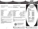
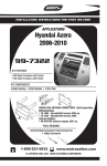
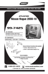
FINAL WIRING CONNECTIONS
Make wiring connections using the EIA color code chart shown below and the
instructions included with the head unit. Metra recommends making connections
as shown below; Strip, Splice, Solder, Tape. Isolate and individually tape off ends
of any unused wires to prevent electrical short circuit.
INSTALLATION
INSTRUCTIONS
METRA / EIA WIRING CODE
70-5511
70-5512*
12V Ignition / Acc. . . . . . . . . . Red
12V Batt / Memory. . . . . . . . . Yellow
STRIP
Ford Premium Sound System Harness
To Integrate Aftermarket Radio
with Factory Amplifiers and Speakers
SPLICE
KIT COMPONENTS
Ground. . . . . . . . . . . . . . . . . . Black*
Power Antenna. . . . . . . . . . . . Blue
Amp Turn-On . . . . . . . . . . . . . Blue / White
Amp Ground. . . . . . . . . . . . . . Black / White
Illumination . . . . . . . . . . . . . . Orange
70-5511
Dimmer . . . . . . . . . . . . . . . . . Orange / White
70-5512 *
SOLDER
Right Front (+) . . . . . . . . . . . . Gray
Right Front (-). . . . . . . . . . . . . Gray / Black
TAPE
Power
Harness
Left Front (+) . . . . . . . . . . . . . White
Left Front (-). . . . . . . . . . . . . . White / Black
Amplifier
Integration
Plug
Right Rear (+) . . . . . . . . . . . . Violet
Right Rear (-) . . . . . . . . . . . . . Violet / Black
Left Rear (+) . . . . . . . . . . . . . Green
Left Rear (-) . . . . . . . . . . . . . . Green / Black
*Requires 70-1704
power harness
TOOLS REQUIRED FOR INSTALLATION
*NOTE: When Black wire is not present, ground radio to vehicle chassis.
All colors may not be present on all leads due to manufacturer’s
specifications.
• Cutting Tool • Tape • Crimping Tool • Connectors
1-800-221-0932
4
Amplifier
Integration
Plug
REV. 04/13/06
INST70-5511
www.metraonline.com
©Copyright 2004 Metra Electronics Corporation
TO INSTALL AN AFTERMARKET RADIO WHILE
KEEPING THE FACTORY AMPLIFIER AND SPEAKERS
NOTES
A
1
Disconnect the negative battery terminal
to prevent an accidental short circuit.
2
Unplug the power and output connectors
from the factory radio. (Figure A)
3
Splice the wire from the aftermarket
radio to the power and amplifier integration harnesses using the color code on
page 4 and the instructions included with
the aftermarket radio.
(Figure B)
4
5
B
Plug the power and amplifier integration
harnesses into the factory power and
output connectors.
Re-connect the negative battery terminal
and test the unit for proper operation.
1
(A)
(B)
(C)
(D)
2
Strip wire ends back 1/2"
Twist ends together
Solder
Tape
3