1
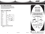
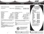
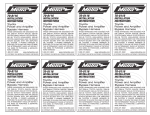
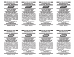
70-5514/AW-WHFPS/CK-WHFPS/DW-5514
Continued from Page 3
5 Unplug the input/output connectors from the factory
amplifier. (Most amps are located in the passenger rear
or behind the dash. Contact Metra’s Technical Support for
further assistance.) (Figure C)
FINAL WIRING CONNECTIONS
Make wiring connections using the EIA color code chart shown below and the
instructions included with the head unit. Metra recommends making connections
as shown below; Strip, Splice, Solder, Tape. Isolate and individually tape off ends
of any unused wires to prevent electrical short circuit.
METRA / EIA WIRING CODE
C
Ford Premium Sound System Harness
to Bypass or Integrate Factory Audio
Components with Aftermarket Audio
Components
12V Ignition / Acc. . . . . . . . . . Red
12V Batt / Memory. . . . . . . . . Yellow
Ground. . . . . . . . . . . . . . . . . . Black*
Power Antenna. . . . . . . . . . . . Blue
6 Join the input/output connectors together using the
Amplifier By-Pass Cable. (Figure D)
Amp Turn-On . . . . . . . . . . . . . Blue / White
Amp Ground. . . . . . . . . . . . . . Black / White
STRIP
KIT COMPONENTS
SPLICE
70-5513
Illumination . . . . . . . . . . . . . . Orange
D
INSTALLATION
INSTRUCTIONS
70-5513/70-5514
AW-WHFPS/CK-WHFPS
DW-5514
Dimmer . . . . . . . . . . . . . . . . . Orange / White
Right Front (+) . . . . . . . . . . . . Gray
Right Front (-). . . . . . . . . . . . . Gray / Black
SOLDER
Power
Harness
TAPE
Amplifier
By-Pass
Cable
Left Front (+) . . . . . . . . . . . . . White
7 Re-connect the negative battery terminal and test the unit
for proper operation.
70-5514/AW-WHFPS
CK-WHFPS/DW-5514
Left Front (-). . . . . . . . . . . . . . White / Black
Amplifier
Integration
Plug
Amplifier
By-Pass
Cable
Right Rear (+) . . . . . . . . . . . . Violet
Right Rear (-) . . . . . . . . . . . . . Violet / Black
Left Rear (+) . . . . . . . . . . . . . Green
Left Rear (-) . . . . . . . . . . . . . . Green / Black
TOOLS REQUIRED FOR INSTALLATION
*NOTE: When Black wire is not present, ground radio to vehicle chassis.
All colors may not be present on all leads due to manufacturer’s
specifications.
• Cutting Tool • Tape • Crimping Tool • Connectors
1-800-221-0932
4
REV. 04/14/06
INST70-5514
www.metraonline.com
©Copyright 2004 Metra Electronics Corporation
70-5514/AW-WHFPS/CK-WHFPS/DW-5514
70-5513
70-5514/AW-WHFPS/CK-WHFPS/DW-5514
70-5514/AW-WHFPS/CK-WHFPS/DW-5514
TO INSTALL AN AFTERMARKET RADIO
WHILE
KEEPING THE FACTORY AMPLIFIER
AND SPEAKERS
TO INSTALL AN AFTERMARKET AMPLIFIER
WHILE
KEEPING THE FACTORY RADIO AND SPEAKERS
TO INSTALL AN AFTERMARKET RADIO WHILE
KEEPING THE FACTORY SPEAKERS
AND BYPASSING THE FACTORY AMPLIFIER
1 Disconnect the negative battery terminal to prevent an
accidental short circuit.
1 Disconnect the negative battery
terminal to prevent an accidental short circuit.
1 Disconnect the negative battery
terminal to prevent an accidental short circuit.
2 Unplug the power and output connectors from the factory
radio. (Figure A)
2 Unplug the input/output connectors from the factory
amplifier. (Most amps are located in the passenger rear
or behind the dash. Contact Metra’s Technical Support for
further assistance). (Figure A)
2 Unplug the power and output connectors from the factory
radio. (Figure A)
A
A
A
3 Join the input/output connectors together using the
Amplifier By-Pass Cable and cut the cable in half.
(Figure B)
3 Splice the wire from the aftermarket radio to the power
and amplifier integration harnesses using the color code
on back cover and the instructions included with the
aftermarket radio. (Figure B)
3 Splice the wire from the aftermarket radio to the power and
amplifier integration harnesses using the color code on the
back cover and the instructions included with the aftermarket radio. (Figure B)
B
B
B
(A)
(B)
(C)
(D)
Strip wire ends back 1/2"
Twist ends together
Solder
Tape
4 Splice the wires in the cable to the wires on the new
aftermarket amplifier using the color code chart on back
cover and the instructions included with the amplifier.
(Figure C)
(A)
(B)
(C)
(D)
Strip wire ends back 1/2"
Twist ends together
Solder
Tape
C
(A)
(B)
(C)
(D)
Strip wire ends back 1/2"
Twist ends together
Solder
Tape
4 Plug the power and amplifier integration harnesses into
the factory power and output connectors.
5 Re-connect the negative battery terminal and test the unit
for proper operation.
1
4 Plug the power and amplifier integration harnesses into
the factory power and output connectors.
Continued on Page 4
5 Re-connect the negative battery terminal and test the unit
for proper operation.
2
3