1
KIT FEATURES
Shaft, DIN and
ISO-DIN unit
provisions
Factory pocket
provisions
KIT COMPONENTS
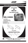
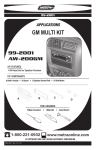
99-3043
AW-304GM
INSTALLATION
INSTRUCTIONS
Radio Housing
APPLICATIONS
Faceplate
Shaft
Supports
(4) 5mm
Flat-head
Screws
(2) Carriage Bolts
(2) Keps Nuts
(2) #6 Selftapping Screws
CAR
PAGE
CHEVROLET
Blazer 1995-97........................................................1-2
S-10 Pickup 1994-97................................................1-2
GMC
Jimmy 1995-97........................................................1-2
Sonoma 1994-97......................................................1-2
ISUZU
Hombre 1996-97......................................................1-2
OLDSMOBILE
Bravada 1995-97.....................................................1-2
ISO-DIN Brackets
TOOLS REQUIRED
Phillips screwdriver
Cutting tool
1-800-221-0932
rev. 271202
Socket wrench
www.metraonline.com
© COPYRIGHT 2001 METRA ELECTRONICS CORPORATION
ALL VEHICLES
4
"B"
Fig. C
"A"
1
Fig. A
"B"
"A"
Fig. B
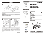
2-SHAFT HEAD UNITS:
Snap the Shaft
Supports into the Radio
Housing.
Slide the
aftermarket head unit into
the kit and secure with
shaft nuts. (see Fig. A)
DIN HEAD UNITS: Slide the DIN cage into the kit and secure by bending the metal locking
tabs down. Slide the aftermarket head unit into the cage until secure. (see Fig. B)
Disconnect the negative battery terminal to prevent an accidental short circuit. Remove (2)
screws above the speedometer cluster. Remove the ashtray and (1) screw exposed in the
ashtray cavity. Remove (2) screws from the lower steering column trim bezel and remove the
bezel. Unclip the dash trim bezel, disconnect the light switch wiring and remove th e bezel.
Remove (4) screws securing the climate control panel and remove the panel. Remove (4)
screws securing the factory head unit/pocket assembly and disconnect the wiring.
ISO-DIN HEAD UNITS: Snap the Faceplate into the Radio Housing. Slide the aftermarket
head unit into the back of the kit. Slide the ISO-DIN Brackets onto the Housing legs and align
the holes in the Brackets with the holes in the unit. Mount the Brackets to the unit with (4) 5mm
Flat-head Screws supplied ("A"). Mount the Brackets to the top of the Housing legs with (2)
#6 Self-tapping Screws ("B"). (see Fig. C)
5
2
3
A
6
B
C
D
A) Strip wire ends back ½"
B) Twist ends together
C) Solder
D) Tape
Remove the pocket from the factory head
unit and slide the side tabs on the Radio
Housing between the mounting tabs on the
pocket.
1
Mount the pocket to the Radio Housing with
(2) Carriage Bolts and (2) Nuts supplied.
Locate the factory wiring harness in the
dash. Metra recommends using the
proper mating adaptor and making
connections as shown. (Isolate and
individually tape off the ends of any
unused wires to prevent electrical short
circuit).
Re-connect the battery terminal and test the unit
for proper operation. Mount the head unit/kit
assembly to the sub-dash with (4) screws
previously removed in step #1.
2