1
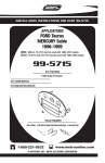
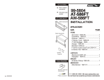
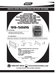
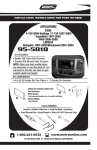
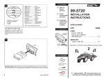
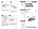
KIT FEATURES
5
DIN unit
provision
Equalizer
provision
Pocket
provision
KIT COMPONENTS
DIN HEAD UNITS: Slide the DIN cage into the Radio Housing and secure by bending the
metal locking tabs outward. Slide the aftermarket head unit into the cage until it snaps into
place.
6
A
Radio Housing
99-5800
INSTALLATION
INSTRUCTIONS
APPLICATIONS
CAR
PAGE
FORD
Expedition 1997-98.........................................1-3
F-150 1997-98...................................................1-3
7
B
TOOLS REQUIRED
C
D
86-5618 - Head unit
removal keys
A) Strip wire ends back ½"
B) Twist ends together
C) Solder
D) Tape
Socket set
Locate the factory wiring harness in the
dash. Metra recommends using the
proper mating adaptor and making
connections as shown. (Isolate and
individually tape off the ends of any
unused wires to prevent electrical short
circuit).
3
Re-connect the battery terminal and test the unit
for proper operation. Snap the head unit/kit
assembly into the sub-dash.
Cutting tool
1-800-221-0932
rev. 4-10-08
Dremel tool
www.metraonline.com
© COPYRIGHT 2001 METRA ELECTRONICS CORPORATION
3
ALL VEHICLES
Fig. A
1
Dash
cavity
Fig. B
Disconnect the negative battery terminal to prevent an accidental short circuit. Place your
index fingers on the inner edges of the a/c vents (shown above) and push inward. Grasp the
exposed lip of each vent opening and pull out on the radio trim bezel. Remove the dash trim
bezel. (The airbag wiring does NOT need to be disconnected). Using Metra's 86-5618, pull
the factory head unit from the dash and disconnect the wiring.
IF THE RADIO OPENING IS DESIRED IN THE UPPER POSITION: Using a dremel tool, cut
and remove the shaded portion of the dash cavity plastic. (see Fig. A).
2
Fig. A
TO AVOID CUTTING THE DASH CAVITY PLASTIC: Trim the points off the mounting clips
located on either side of the Radio Housing. (see Fig. B). Use the radio opening in the lower
position for the remainder of the installation.
Back
wall
4
Inside edge
of sub-dash
Back
wall
Fig. B
Inside edge
of sub-dash
Fig. A
Fig. B
REMOVE THE REAR SUPPORT BRACKET FROM THE DASH CAVITY USING ONE OF
THE FOLLOWIING METHODS: Remove (1) 7mm hex-head bolt securing the bottom of the
bracket to the back wall of the sub-dash and (2) 7mm hex-head bolts securing the top of the
bracket to the inside edge of the sub-dash. Remove the bracket. (see Fig. A). OR Remove
(1) 7mm hex-head bolt securing the bottom of the bracket to the back wall of the sub-dash and
cut the bracket flush with the top edge of the radio opening. Remove the bracket. (see Fig. B)
1
IF AN EQUALIZER WILL NOT BE INCLUDED: Skip to step #5.
IF AN EQUALIZER WILL BE INCLUDED: Cut and remove the pocket (shaded) from the
Radio Housing. (see Fig. A). Slide the equalizer into the Housing and secure with plumber's
tape. (see Fig. A)
2