1
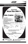
INSTALLATION INSTRUCTIONS FOR PART 99-5715
APPLICATIONS
FORD Taurus
MERCURY Sable
1996-1999
NOTE: Metra’s 70-5715 must be used with 1996-1997 models.
Metra’s 70-5715 and 70-5716 must be used with 1998-1999 models.
99-5715
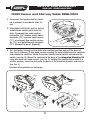
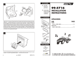
KIT FEATURES
• DIN Radio Provision
KIT COMPONENTS
A) Integrated Mounting Kit
A
TOOLS REQUIRED:
Torx Driver • 86-5618 Head Unit Removal Keys • Dremel Tool
1-800-221-0932
www.metraonline.com
© COPYRIGHT 2007 METRA ELECTRONICS CORPORATION
99-5715
TABLE OF CONTENTS
Dash Disassembly
- FORD Taurus 1996-1999. . . . . . . . . . . . . . . . . . . . . . . . . . . . . . . 1
- MERCURY Sable 1996-1999. . . . . . . . . . . . . . . . . . . . . . . . . . . . 1
Kit Preparation . . . . . . . . . . . . . . . . . . . . . . . . . . . . . . . . . . . .. . . . . . . 2
Kit Assembly
- DIN Radio Provision with Pocket. . . . . . . . . . . . . . . . . . . . . . . . . . . 3,4
Final Assembly .. . . . . . . . . . . . . . . . . . . . . . . . . . . . . . . . . . . . . . . . . . .5
*Note:
Refer also to the instructions included with the aftermarket radio.
99-5715 DASH DISASSEMBLY
AND KIT PREPARATION
FORD Taurus and Mercury Sable 1996-1999
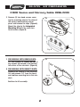
1 Disconnect the negative battery terminal to prevent an accidental short circuit.
A
"A"
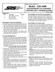
2 Using Metra's 86-5618, pull the factory
radio/climate control panel from the
dash. Disconnect the audio system
connectors ("A"), blower motor switch
connector ("B"), vacuum hose harness
("C"), a/c damper door switch connector ("D"), and potentiometer connector
("E"). Remove the panel. (Figure A)
"E"
"D"
"C"
"B"
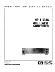
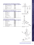
3 Turn the factory climate control dials into a vertical position and pull the dials off.
(see Fig. A). Remove (2) hex-head screws securing the outer climate control switches
and remove the switches. Unclip the center climate control switch and remove the
switch. (see Fig. B). Mount the switches to the back of the Integrated Mounting Kit
using the same hex-head screws. (see Fig. C). Holding the climate control dials in a
vertical position, insert the dials onto the posts of the mounted switches and secure.
(see Fig. D)
Continue kit preparation on next page.
Fig. A
Fig. B
Fig. D
Fig. C
1
99-5715
KIT PREPARATON
FORD Taurus and Mercury Sable 1996-1999
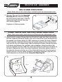
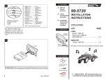
1 Remove (2) torx-head screws securing the mounting clips to the sides of
the factory radio/climate control
panel and remove the clips. (Figure A)
Mount the clips to the Integrated
Mounting Kit with the same torxhead screws. (Figure B)
A
Fig. A
Fig. B
1 FOR MODELS WITH BENCH SEATS:
Cut and remove the shaded portion of
the support rib located in the bottomleft corner of the sub-dash. (Figure A)
A
2 FOR MODELS WITH BUCKET SEATS:
Relocate the module in the sub-dash.
Cut and remove 1/4" from the top of
each bottom mounting tab in the subdash.
Fig. A
Continue to kit assembly.
2
99-5715 KIT ASSEMBLY
DIN RADIO PROVISION
*Note: Refer also to the instructions included with the aftermarket radio.
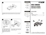
1 Slide the DIN cage into the Integrated
Mounting Kit and secure by bending
the metal locking tabs down. Slide the
aftermarket head unit into the cage
until secure. (Figure A)
A
Fig. A
Continue to final assembly.
FORD Taurus and Mercury Sable 1996-1999
*Note: Refer also to the instructions included with the aftermarket radio.
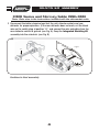
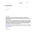
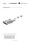
1 Open the trunk, remove (4) pop-clips from the driver's side trunk liner and remove
the liner. (Figure A) Locate the factory tuner on the wall of the trunk and disconnect
the speaker and antenna plugs (it is NOT necessary to remove the tuner). (Figure B)
Plug the speaker extension lead into the unit speaker plug and the antenna extension lead into the unit antenna plug. Slide the extension harness through the space
in the back seat between the seat back and seat bottom. Unclip the rocker trim,
tuck the extension harness under the carpet and stretch the harness to the back of
the dash. (Replace the rocker trim when completed). Splice the speaker leads on
the extension harness into the rear of the aftermarket head unit. Plug the factory
wiring harnesses into the switch connectors (previously mounted in step #2) and
audio connectors on the back of the Integrated Mounting Kit.
A
Fig. A
(located under
the rear deck)
Fig. B
3
99-5715 KIT ASSEMBLY
FORD Taurus and Mercury Sable 1996-1999
*Note: Refer also to the instructions included with the aftermarket radio.
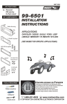
1 Re-connect the battery terminal and test the unit, climate controls and rear
defroster for proper operation. (If the rear defroster does not work, cut the black
wire on the switch plug at position "A" and connect the wire extending from the
rear defroster switch to ground. (see Fig. A). Snap the Integrated Mounting Kit
assembly into the sub-dash. (see Fig. B)
A
Fig. B
"A"
Fig. A
Continue to final assembly.
4
99-5715 FINAL ASSEMBLY
FINAL ASSEMBLY
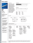
A
(A) Strip wire ends back 1/2"
B
B) Twist ends together
C) Solder
D) Tape
C
D
1
Locate the factory wiring harness in the dash. Metra recommends using the
proper mating adapter and making connections as shown. (Isolate and individually tape off the ends of any unused wires to prevent electrical short circuit.)
2
Re-connect the negative battery terminal and test the unit for proper operation.
3
Reassemble in reverse order of disassembly using the 99-5715 Integrated
Mounting Kit in place of the factory radio climate control panel.
FINAL WIRING CONNECTIONS
Make wiring connections using the EIA color code chart shown below and the instructions included with the
head unit. Metra recommends making connections as shown below; Strip, Splice, Solder, Tape. Isolate and
individually tape off ends of any unused wires to prevent electrical short circuit.
METRA / EIA WIRING CODE
12V Ignition / Acc. . . . . . . . . . Red
Right Front (+) . . . . . . . . . . . . Gray
12V Batt / Memory. . . . . . . . . Yellow
Right Front (-). . . . . . . . . . . . . Gray/ Black
Ground. . . . . . . . . . . . . . . . . . Black*
Left Front (+) . . . . . . . . . . . . . White
Power Antenna. . . . . . . . . . . . Blue
Left Front (-). . . . . . . . . . . . . . White / Black
Amp Turn-On . . . . . . . . . . . . . Blue / White
Right Rear (+) . . . . . . . . . . . . Violet
Amp Ground. . . . . . . . . . . . . . Black / White
Right Rear (-) . . . . . . . . . . . . . Violet / Black
Illumination . . . . . . . . . . . . . . Orange
Left Rear (+) . . . . . . . . . . . . . Green
Dimmer . . . . . . . . . . . . . . . . . Orange / White
Left Rear (-) . . . . . . . . . . . . . . Green / Black
*NOTE: When a Black wire is not present, ground radio to vehicle chassis.
All colors may not be present on all leads due to manufacturer’s specifications.
5
99-5715 INSTRUCTIONS
1-800-221-0932
www.metraonline.com
REV. 12/27/07 © COPYRIGHT 2007 METRA ELECTRONICS CORPORATION INST99-5715