1
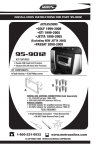
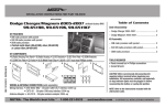
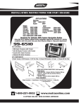
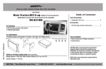
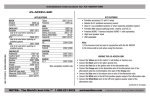
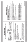
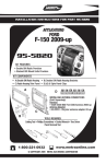
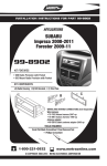
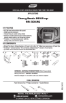
INSTALLATION INSTRUCTIONS FOR PART 99-9011
Applications
VW
CC 2009-10/EOS 2007-10/New Jetta 2005-10
GLI 2008-10/GTI 2006-10/Passat 2006-10
Rabbit 2006-09/R32 2008/Tiguan 2009-10
Golf 2010
99-9011
KIT FEATURES
• DIN Head Unit Provision with pocket
• ISO Head Unit Provision with pocket
• Double DIN Head Unit Provision
• ISO Stacked Head Unit Provision
KIT COMPONENTS
A) Radio Housing • B) ISO Brackets • C) ISO Trim Plate • D) DDIN Brackets • E) DDIN Trim Plate • F) Pocket
B
A
E
F
C
D
WIRING AND ANTENNA CONNECTIONS (Sold Separately)
Wire harness:
• XSVI-9003-NAV VW Interface 2003-up
Antenna adapter:
• 40-EU55-adapter for amplified antenna 2002-up
TOOLS REQUIRED:
T-20 Torx Screwdriver • Flat Blade Screwdriver Or Panel Removal Tool
1-800-221-0932
www.metraonline.com
© COPYRIGHT 2004-2010 METRA ELECTRONICS CORPORATION
99-9011
TABLE OF CONTENTS
• Dash Disassembly
- GLI 2008 -10................................................................................1,2
- GTI 2006-09.................................................................................1,2
- New Jetta 2005-10......................................................................1,2
- Rabbit 2006-09............................................................................1,2
- R32 2008 ....................................................................................1,2
- CC 2009-10 ................................................................................... 3
- Passat 2006-10 ............................................................................ 3
- Golf 2010, GTI 2010, Jetta Sport Wagon ...................................... 3
- Tiguan 2009-10............................................................................. 4
- Eos 2007-10.................................................................................. 5
• Kit Assembly:
- DIN Head Unit Provision with Pocket ............................................6
- ISO Head Unit Provision with Pocket .............................................7
- Double DIN Head Unit Provision.....................................................8
- Stacked ISO Head Unit Provision ...................................................9
• Final Assembly .............................................................................10
KNOWLEDGE IS POWER
Enhance your installation and fabrication skills by
enrolling in the most recognized and respected
mobile electronics school in our industry.
Log onto www.installerinstitute.com or call
800-354-6782 for more information and take
steps toward a better tomorrow.
Metra reccommends MECP certified
technicians.
99-9011
DASH DISASSEMBLY
NEW JETTA 2005-10/GLI 2008-10
GTI 2006-09/RABBIT 2006-09
R32 2008
1
Disconnect the negative battery
terminal to prevent an accidental
short circuit.
2
Unclip and remove the grille from
the top-center of dash. (Figure A)
3
Remove one T-20 torx screw from
black insert from under grille
removed in step one. (Figure B)
4
Remove insert. (Figure C)
5
Remove two T-20 torx screws from
under black insert removed in step
two. (Figure D)
A
B
D
C
1
99-9011
DASH DISASSEMBLY
NEW JETTA 2005-10/GLI 2008-10
GTI 2006-09/RABBIT 2006-09
R32 2008
6
Unsnap and remove the vent
assembly above the radio. (Figure E)
7
Remove two T-20 torx screws from
top sides of radio/climate panel.
(Figure F)
8
Remove panel. (Figure G)
9
Remove four T-20 torx screws to
remove the radio. (Figure H)
E
F
H
G
2
99-9011
DASH DISASSEMBLY
CC 2009-10 / PASSAT 2006-10
JETTA SPORT WAGON 2010
GOLF 2010 / GTI 2010
1 Disconnect the negative battery
terminal to prevent an accidental
short circuit.
A
2 Unclip and remove trim panel surrounding radio. (Figure A)
FM2
FM
103.7MHZ
CD
AM
SCAN
ON
BASS
BAL
TREB
FAD
TUNE
VOL
3 Remove (4) T-20 Torx screws to
remove radio.
PASSENGER
OFF
AIR BAG
AC
72
1
80
64
3
2 3
4
99-9011
DASH DISASSEMBLY
TIGUAN 2009-10
1
Disconnect the negative battery
terminal to prevent an accidental
short circuit.
2
Unclip and remove passenger air
bag light panel to the right of the
hazard light button. (Figure A)
3
Unclip and remove the panel with
the two slots in it to the left of the
hazard light button. (Figure A)
4
Remove (2) T-20 Torx screws
exposed behind the two panels
removed in the two previous steps.
(Figure B)
5
Unclip and remove the trim panel
surrounding the radio. (Figure C)
6
Remove (4) T-20 Torx screws securing the radio. Unplug and remove
the radio. (Figure D)
A
PASSENGER
PASSENGER
AIRBAG
BAG
AIR
PASSENGER
AIR BAG
B
AF
PASSENGER
AIR BAG
D
C
AF
PASSENGER
AIR BAG
AF
AF
4
99-9011
DASH DISASSEMBLY
EOS 2007-2010
A
1
Disconnect the negative battery
terminal to prevent an accidental
short circuit.
2
Unclip and remove the radio trim
panel. (Figure A)
3
Remove the (4) screws securing the
radio. Unplug and remove the radio.
(Figure B)
B
5
99-9011
KIT ASSEMBLY
DIN HEAD UNIT PROVISION WITH POCKET
1
Slide the DIN cage into the Radio
Housing and secure by bending
the metal locking tabs down.
(Figure A)
A
2 Slide the aftermarket head unit
into the cage and secure.
(Figure B)
3 Snap the pocket into the radio housing. (Figure C)
B
C
6
99-9011
KIT ASSEMBLY
ISO HEAD UNIT PROVISION WITH POCKET
1
Mount the ISO Brackets to the
head unit with the screws supplied with the unit. (Figure A)
2
Slide the head unit into the radio
opening until the side clips
engage. (Figure B)
3
Snap the ISO Trim Plate into the
Radio Housing. (Figure C)
A
B
4 Snap the pocket into the radio housing. (Figure C)
C
7
99-9011
KIT ASSEMBLY
DOUBLE DIN HEAD UNIT PROVISION
1 Cut and remove center divide from
radio housing. (Figure A)
A
2 Snap the DDIN brackets to the
inside edge of the radio housing.
(Figure B)
3 Slide the DDIN radio unit into the
DDIN bracket/radio housing assembly and secure the unit to the kit
using the screws supplied with the
head unit. (Figure C)
B
4 Snap the DDIN trim-plate onto the
housing/radio assembly. (Figure C)
C
8
99-9011
KIT ASSEMBLY
STACKED ISO HEAD UNIT PROVISION
1 Cut and remove center divider
from radio housing. (Figure A)
A
2 Snap the DDIN brackets to the
inside edge of the radio housing.
(Figure B)
3 Slide the stacked ISO DIN units into
the DDIN bracket/radio housing
assembly and secure the units to the
kit using the screws supplied with
the head units. (Figure C)
B
4 Snap the DDIN trim-plate onto the
housing/radio assembly. (Figure C)
C
9
99-9011
FINAL ASSEMBLY
FINAL ASSEMBLY
A
B
C
A)
Strip wire ends back 1/2"
B)
Twist ends together
C)
Solder
D)
Tape
D
1
2
3
Locate the factory wiring harness in the dash. Metra recommends using the
proper mating adapter and making connections as shown. (Isolate and individually
tape off the ends of any unused wires to prevent electrical short circuit.)
Re-connect the negative battery terminal and test the unit for proper operation.
Reassemble in reverse order of disassembly.
FINAL WIRING CONNECTIONS
Make wiring connections using the EIA color code chart shown below and the instructions included with the head
unit. Metra recommends making connections as shown below; Strip, Splice, Solder, Tape. Isolate and individually
tape off ends of any unused wires to prevent electrical short circuit.
METRA / EIA WIRING CODE
12V Ignition / Acc . . . Red
12V Batt / Memory . . Yellow
Ground . . . . . . . . . . . Black*
Power Antenna . . . . . Blue
Amp Turn-On . . . . . . Blue / White
Amp Ground . . . . . . . Black / White
Illumination. . . . . . . . Orange
Dimmer . . . . . . . . . . Orange / White
Right Front (+) . . . . . Gray
Right Front (-). . . . . . Gray/ Black
Left Front (+) . . . . . . White
Left Front (-) . . . . . . . White / Black
Right Rear (+). . . . . . Violet
Right Rear (-) . . . . . . Violet / Black
Left Rear (+). . . . . . . Green
Left Rear (-) . . . . . . . Green / Black
*NOTE: When a Black wire is not present, ground radio to vehicle chassis.
All colors may not be present on all leads due to manufacturer’s specifications.
1-800-221-0932
www.metraonline.com
REV. 04/26/10 © COPYRIGHT 2004-2010 METRA ELECTRONICS CORPORATION
10
INST99-9011