1
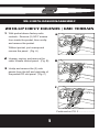
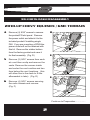
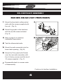
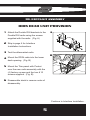
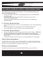
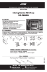
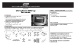
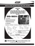
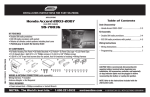
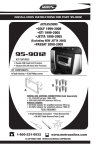
INSTALLATION INSTRUCTIONS FOR PART 99-3307G
APPLICATIONS
CHEVY EQUINOX
GMC TERRAIN
2010-UP
99-3307G
KIT FEATURES
• ISO Mount With Pocket
• DDIN Head Unit Provisions
• Painted Gray To Match Factory Color And Finish
KIT COMPONENTS
• A) Radio Brackets • B) Radio Trim Panel • C) Pocket • D) (2) #10 Panel Clips • E) (2) #10 3/4 Phillips screws
• F) (6) #8 3/8”Phillips screws • G) Interface/Harnesses
A
B
C
D
E
F
G
ANTENNA CONNECTIONS (Sold Separately)
• 40-EU55 – European Antenna Adapter 2006-Up
The included interface with this kit is designed to retain Onstar, and retain factory warning chimes.
It also provides a 12 volt accessory output, mute, park brake, speed signal and reverse outputs.
PURCHASED SEPARATELY – Use the AXXESS ASWC (steering wheel control interface)
for retention of factory wheel controls and the ability to control
the aftermarket radio with the factory radio buttons.
TOOLS REQUIRED
• Panel Removal Tool • Phillips Screwdriver • Socket Wrench
• Cutting Tool (Dremel / Air Saw)
METRA. THE WORLD’S BEST KITS.™
1-800-221-0932
metraonline.com
© COPYRIGHT 2004-2011 METRA ELECTRONICS CORPORATION
TABLE OF CONTENTS
DASH DISASSEMBLY
• 2010-UP CHEVY EQUINOX / GMC TERRAIN . . . . 1-2
PREPARATION
• 2010-UP CHEVY EQUINOX / GMC TERRAIN . . . . . . 3
KIT ASSEMBLY
2010-UP CHEVY EQUINOX / GMC TERRAIN
• ISO DIN HEAD UNIT PROVISION . . . . . . . . . . . . . . . 4
• DDIN HEAD UNIT PROVISION . . . . . . . . . . . . . . . . . . 5
INTERFACE INSTALLATION INSTRUCTIONS
• 2010-UP CHEVY EQUINOX / GMC TERRAIN . . . . 6-9
CAUTION : Metra recommends disconnecting the negative battery
terminal before beginning any installation. All accessories, switches and especially air bag indicator lights must be plugged in before
reconnecting the battery or cycling the ignition.
*NOTE: Refer also to the instructions included with the aftermarket radio.
KNOWLEDGE IS POWER
Enhance your installation and fabrication skills by
enrolling in the most recognized and respected
mobile electronics school in our industry.
Log onto www.installerinstitute.com or call
800-354-6782 for more information and take steps
toward a better tomorrow.
Metra recommends MECP certified
technicians
99-3307G DASH DISASSEMBLY
2010-UP CHEVY EQUINOX / GMC TERRAIN
1 With pocket above factory radio
A
controls - Remove (2) 9/32” screws
from inside the pocket, then unclip
and remove the pocket.
Without pocket, just unsnap and
remove the panel. (Fig. A)
2 Unsnap, unplug, and remove the
radio/ climate control panel. (Fig. B)
B
3 Unclip and remove the (2) side
panels from the left and right side of
the pocket/CD slot panel. (Fig. C)
C
Continued on PG. 2 ......................
1
99-3307G DASH DISASSEMBLY
2010-UP CHEVY EQUINOX / GMC TERRAIN
4 Remove (4) 9/32” screws to remove
the pocket/CD slot panel. Remove
the power outlet and attach it to the
included pocket if installing single
DIN. If you are mounting a DDIN the
power outlet will not be retained with
this kit. Remove the rubber bottom
from the factory pocket and save it
for final assembly. (Fig. D)
D
E
5 Remove (2) 9/32” screws from each
a/c vent then unclip and remove the
vents. Remove the screws inside
and under the vent cavities and two
from below the vent locations. (this
will allow flex in the dash to fit the
aftermarket in later). (Fig. E)
E
6 Remove (4) 9/32” screws securing
the radio chassis and remove.
(Fig. F)
Continue to Preparation ...............
2
99-3307G PREPARATION
DASH PREPARATION
1 A small section of the dash must be
cut to allow the kit and new radio to
fit into the dash. Using a cutting tool
(we recommend a small saw blade),
remove the lip from the section of dash
just above the original CD slot location.
(Fig. A - Upper shaded portion. Cut
along dotted line)
A
2
It is also recommended that a portion of
the sub dash in front side of the console
be removed for depth. (Fig. A - Lower
shaded portion. Cut along dotted line)
KIT PREPARATION
1 Clip the included speed clips onto the
front legs of the brackets. (Fig. B)
B
Continue to Kit Assembly .............
3
99-3307G KIT ASSEMBLY
ISO DIN HEAD UNIT PROVISION
1 Mount the brackets to aftermarket
A
radio with the screws supplied with
the unit. (Fig. A)
2 Mount the pocket to the brackets
with the (6) #8 screws included.
(Fig. A)
B
3 Skip to page 6 for Interface
Installation Instructions.
4 Test the aftermarket radio.
5 Mount the radio assembly into the
lower dash opening. (Fig. B)
6 Mount the Trim panel with Pocket
over the new radio assembly with
the (4) factory screws and the two #
10 screws supplied. (Fig. C)
7 Reassemble dash in reverse order
of disassembly.
Continue to Interface Installation...
4
99-3307G KIT ASSEMBLY
DDIN HEAD UNIT PROVISION
1 Attach the Double DIN brackets to the
Double DIN radio using the screws
supplied with the radio. (Fig. A)
A
2 Skip to page 6 for Interface
Installation Instructions.
3 Test the aftermarket radio.
B
4 Mount the DDIN radio into the lower
dash opening. (Fig. B)
5 Mount the Trim panel with Pocket
over the new radio assembly with the
(4) factory screws and the two # 10
screws supplied. (Fig. B)
6 Reassemble dash in reverse order of
disassembly.
Continue to Interface Installation...
5
99-3307G INTERFACE INSTALLATION INSTRUCTIONS
INTERFACE INSTALLATION INSTRUCTIONS
*Important: Before beginning any of the following, disconnect the negative
battery terminal to prevent an accidental short circuit.
The included interface with this kit is designed to retain Onstar, and retain
factory warning chimes. It also provides a 12 volt accessory output, mute, park
brake, speed signal and reverse outputs.
PURCHASED SEPARATELY – Use the AXXESS ASWC (steering wheel
control interface) for retention of factory wheel controls and the ability to
control the aftermarket radio with the factory radio buttons.
INTERFACE COMPONENTS
• A) Interface • B) Harness
A
B
TOOLS REQUIRED FOR INSTALLATION
• Cutting Tool • Tape • Crimping Tool • Connectors (I.E. butt-connectors, bell
caps, ECT…) • Female Spade Connectors (Optional)
M4
ISO
M3.5
IGNITION
TERMINALS
M2.6
M3
6
2.5
WIRE
CUTTER
1.5
M5
6
99-3307G INTERFACE INSTALLATION INSTRUCTIONS
INSTALLING THE INTERFACE
*Important: Before beginning any of the following, disconnect the negative
battery terminal to prevent an accidental short circuit.
1. From the 16 way harness:
•
•
•
•
•
•
•
•
•
•
•
•
Connect the red wire to the ignition/accessory wire of the aftermarket radio
Connect the Orange/White wire to the illumination wire of the aftermarket
radio. If the aftermarket radio has no illumination wire just tape off the
Orange/White wire.
Connect the blue/white wire to the amp turn on wire of the aftermarket radio.
Connect the white wire to the left front positive speaker output of the
aftermarket radio
Connect the white/black wire to the left front negative speaker output of the
aftermarket radio
Connect the gray wire to the right front positive speaker output of the
aftermarket radio
Connect the gray/black wire to the right front negative speaker output of the
aftermarket radio
Connect the green wire to the left rear positive speaker output of the
aftermarket radio
Connect the green/black wire to the left rear negative speaker output of the
aftermarket radio
Connect the purple wire to the right rear positive speaker output of the
aftermarket radio
Connect the purple/black wire to the right rear negative output of the
aftermarket radio
Connect the Brown wire to the mute wire of the aftermarket radio. If the
aftermarket radio does not have a Mute wire, tape up the Brown wire.
7
99-3307G INTERFACE INSTALLATION INSTRUCTIONS
The following wires on the 16 pin harness are for the aftermarket radios
that have navigation built in:
•
•
•
Connect the Light Green wire to the parking brake wire of the aftermarket
navigation radio.
Connect the Blue/Pink wire to the VSS or speed sense wire of the
aftermarket navigation radio.
Connect the Green/Purple wire to the reverse wire of the aftermarket
navigation radio.
2. From the 44 way harness:
•
•
•
Connect the Yellow wire to the 12 volt constant/battery wire of the aftermarket
radio
Connect the Black wire to the ground wire of the aftermarket radio
Connect the RCA’s to the AUX input of your aftermarket radio.
3. From the 18 way harness:
•
•
•
Connect the Black wire with the ring terminal to the radio chassis. (This wire
must be grounded here by itself for the interface to work properly)
The Black/Yellow wire and additional 12 pin harness will be discussed later in
this manual
Connect the RCA’s to the AUX input of your aftermarket radio (if equipped)
Chime Volume Adjustment
To adjust the chime volume, use a small screwdriver to rotate the potentiometer,
located on the 16 pin harness side of the interface, clockwise to make the chime
louder and counterclockwise to make the chime softer.
Onstar Level Adjustment
To adjust the Onstar volume level find the Black/Yellow wire on the 22 pin
8
99-3307G INTERFACE INSTALLATION INSTRUCTIONS
harness. Push the blue Onstar button, while the voice is speaking tap the
Black/Yellow wire to ground. There are 4 volume settings for Onstar; once
the 4th setting is reached and the Black/Yellow wire is tapped to ground it will
automatically go back to the first volume setting. Once the volume is set it will
stay at that volume until the Black/Yellow wire is tapped to ground again.
This can be set during installation and then left alone.
If user adjustment is desired, the customer may also tap volume up or down to
adjust the Onstar level.
12 Pin Harness
The 12 pin harness that is attached to the interface is for use with the ASWC
(sold separately). The AXXESS ASWC is the interface for retaining factory
steering wheel controls, but can also be used for retaining the factory radio
controls in the center of the dash.
Please refer to the ASWC instructions for programming.
Installing the Interface
1. With all the connections completed, plug the 22 and 16 pin harnesses into
the interface.
2. Plug the 30 pin GM harness into the vehicle side harness, and plug the
aftermarket radio harness into the aftermarket radio.
3. Reconnect the negative battery terminal.
4. Cycle the key by turning the ignition on then back off, then back on again to
test the radio.
Testing the Interface
Turn the ignition on, and then turn the aftermarket radio on.
Push the Onstar button, the radio should turn off and you should hear Onstar.
Push the Onstar cancel button and the radio should come back on.
9
REV. 2/15/11
INSTALLATION INSTRUCTIONS FOR PART 99-3307G
METRA. THE WORLD’S BEST KITS.™
1-800-221-0932
metraonline.com
© COPYRIGHT 2004-2011 METRA ELECTRONICS CORPORATION