1
iConverter®
1-Module Redundant Chassis
User Manual
140 Technology #500, Irvine, CA 92618
Phone: (949) 250-6510; Fax: (949) 250-6514
Table of Contents
1.0
1.1
1.2
1.3
2.0
2.1
2.2
2.3
3.0
3.1
3.1.1
3.1.2
3.1.3
3.1.4
3.2
3.3
3.4
4.0
4.1
4.1.1
5.0
5.1
5.2
6.0
7.0
INTRODUCTION ............................................................................. 3
General Description ....................................................................... 3
About This Manual ........................................................................ 3
Chassis Model Numbers ............................................................... 4
INSTALLATION ............................................................................... 4
Chassis Installation ....................................................................... 4
Module Installation ........................................................................ 5
Fiber Installation ............................................................................ 5
CONFIGURATION........................................................................... 6
Redundant Power Configurations ................................................ 6
AC/DC Power Option (Low Voltage Barrel) .................................. 6
24 VDC Option (Low Voltage Terminal) ........................................ 7
48 VDC Option (High Voltage Terminal) ....................................... 8
Power over Ethernet (PoE) Option ............................................. 10
LED Indicators ............................................................................. 11
Contact Closure Sensors ............................................................ 12
Ethernet Backplane ..................................................................... 14
CHASSIS MANAGEMENT ............................................................ 15
Overview ...................................................................................... 15
Configuring and Monitoring the Chassis .................................. 15
APPLICATIONS ............................................................................ 21
Battery Backup with Alarms ....................................................... 21
Contact Closure Sensor Configuration ...................................... 22
SPECIFICATIONS ......................................................................... 23
TECHNICAL SUPPORT ................................................................ 26
Page 2
1.0
INTRODUCTION
1.1
General Description
The iConverter 1-Module chassis features a number of redundant power inputs,
UTP port and alarm options. It supports primary and secondary power input
options and variety of power connection types. By utilizing the optional UTP
ports, the unit can be powered from a connected Power Sourcing Equipment
(PSE). Optional contact closure sensors are provided for connection to external
alarm indicators. By installing a managed iConverter module into the chassis,
the chassis functions can be remotely managed by Telnet and SNMP software
such as Omnitron’s NetOutlook® Management software.*
1.2
About This Manual
This document supports release 1.1 of the iConverter 1-Module Redundant
chassis.
*iConverter management module and NetOutlook must be at version 3.3c or
higher.
Page 3
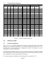
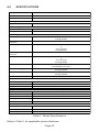
1.3
Chassis Model Numbers
Primary Power
Model
Contact
Closure
Two UTP
RJ-45
Ports
Low Voltage
DC-Barrel
(9-24V)
Low Voltage
DC-Terminal
(9-24V)
Backup Power
High Voltage
DC-Terminal
(24-60V)
RJ-45
POE
Low Voltage
DC-Barrel
(9-24V)
Low Voltage
DC-Terminal
(9-24V)
AC/DC
Power
Supply
8245-111
x
x
Two US
8245-112
x
x
Two Univ.
8246-111
x
x
x
Two US
8246-112
x
x
x
Two Univ.
8246-511
x
x
x
One US.
8246-512
x
x
x
One Univ.
8247-111
x
x
x
Two US
8247-112
x
x
x
Two Univ.
8247-121
x
x
x
One US
8247-122
x
x
x
One Univ.
8247-220
x
8247-311
x
x
x
8247-312
x
x
x
8247-320
x
x
8248-111
x
x
x
x
One Univ.
x
x
x
x
One US.
Two US
8248-112
x
x
x
8248-121
x
x
x
x
One US.
8248-122
x
x
x
x
One Univ.
8248-220
x
x
8248-311
x
x
x
x
8248-312
x
x
x
x
8248-320
x
x
x
8248-511
x
x
x
x
8248-512
x
x
x
x
8248-520
x
x
x
x
Two Univ.
x
Two US.
Two Univ.
x
One US.
One Univ.
x
-
Table 1: Chassis Model Numbers
2.0
INSTALLATION
2.1
Chassis Installation
The iConverter 1-Module Redundant chassis is designed to accommodate
wall-mount or tabletop installations. For wall-mounting, the 8249-0 iConverter
Wall-Mount kit (sold separately) is designed to attach the chassis to a wall,
backboard or other flat surface.
For tabletop installations, place the unit on a flat level surface. Attach the rubber
feet to the bottom of the chassis to prevent the unit from sliding. Make sure the
unit is placed in a safe, dry and secure location.
For external power installation and configuration, see section 3.0.
Page 4
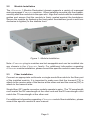
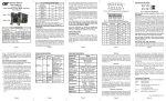
2.2
Module Installation
The iConverter 1-Module Redundant chassis supports a variety of managed
and unmanaged iConverter modules. When installing a module into the chassis,
carefully slide the module into the open slot. Align the module with the installation
guides and ensure that the module is firmly seated against the backplane.
Secure the module by fastening the front panel thumbscrew (push in and turn
clockwise to tighten) to the chassis front.
Figure 1: Module Installation
Note: iConverter plug-in modules are hot-swappable and can be installed into
any chassis in the iConverter family. For additional information regarding
iConverter module installation, please consult the specific module’s user manual.
2.3
Fiber Installation
Connect an appropriate multimode or single-mode fiber cable to the fiber port
of the installed module. It is important to make sure that the transmit (TX) is
attach to the receive side of the device at the other end and the receive (RX) is
attach to the transmit side.
Single-fiber (SF) media converter models operate in pairs. The TX wavelength
must match the RX wavelength at the other end and the RX wavelength must
match the TX wavelength at the other end.
For additional information regarding iConverter module fiber installation, please
consult the specific module’s user manual.
Page 5
3.0
CONFIGURATION
3.1
Redundant Power Configurations
The chassis support multiple redundant load sharing power configurations.
The power is connected to the back of the chassis with connectors labeled
“Pwr1” and “Pwr2”. “Pwr1” is the primary power connection and “Pwr2” is the
backup. There are four primary power options and two backup options. The
combinations of primary and backup power include low voltage barrel
connector, low voltage terminal, high voltage terminal and PoE from the UTP
ports. The manner in which the power is connected will depend on the model
selected. Refer to Table 1 for the specific power input options supported on
each chassis model.
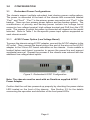
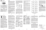
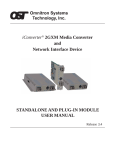
3.1.1
AC/DC Power Option (Low Voltage Barrel)
To power the chassis using AC/DC adapter, connect the AC/DC adapter to the
AC outlet. Then connect the barrel plug at the end of the wire on the AC/DC
adapter to the 2.5mm DC barrel connector on the chassis. A wire saddle is
located below each barrel connector to secure the power line and prevent
accidental removal. Repeat the process if the chassis was ordered with the
additional low voltage barrel option.
Figure 2: Redundant AC/DC Configuration
Note: The chassis must be used with an Omnitron supplied AC/DC
Power Adapter.
Confirm that the unit has powered up properly by checking the power status
LED located on the front of the chassis. See Section 3.2 for the details
concerning the operation and definition of the front panel LEDs.
Page 6
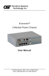
3.1.2
24 VDC Option (Low Voltage Terminal)
The 8247-x2x, 8247-2xx, 8248-x2x and the 8248-2xx chassis require
9-24 VDC/1.5 Amps power input. The appropriate overload protection should
be provided at the power source. To power the chassis using 24 VDC power
source, locate the 24 VDC circuit breaker and switch the circuit breaker to the
off position. Prepare the power cable using a two-conductor insulated wire
with a 14 AWG gauge (not supplied). Cut the power cable to the length required.
Strip approximately 3/8 of an inch of insulation from the power cable wires.
Connect the power cable to the chassis by fastening the stripped ends to the 24
VDC power connector. Repeat the process if the chassis was ordered with the
additional low voltage terminal option.
Warning: Note the wire colors used in making the positive, negative and
ground connections. Use the same color assignment for the connection
at the circuit breaker.
Note: The 9-24VDC power input can accept an input voltage up to 28VDC.
Connect the power wires to the circuit breaker and switch the circuit breaker
ON. Confirm that the unit has powered up properly by checking the power
status LED located on the front of the installed chassis. See Section 3.2 for the
details concerning the operation and definition of the front panel LEDs.
+
-
Figure 3: Redundant 24 VDC Configuration
Page 7
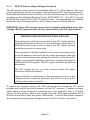
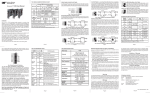
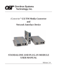
3.1.3
48 VDC Option (High Voltage Terminal)
The DC power source should be available within 5 ft. of the chassis. The over
current protection for the connection with centralized DC shall be provided in
the building installation and shall be a UL listed breaker rated at 20 Amps, and
installed per the National Electrical Code, ANSI/NFPA-70. The 8247-3xx and
the 8248-3xx require 24-60 VDC/0.6 Amps power. The appropriate overloading
protection should be provided on all DC power source outlets utilized.
WARNING: Only a DC power source that complies with safety extra low
voltage (SELV) requirements can be connected to the DC-input power.
WARNING REGARDING EARTHING GROUND
This equipment shall be connected to the DC supply system
earthing electrode conductor or to a bonding jumper from an
earthing terminal bar or bus to which the DC supply system
earthing electrode is connected.
This equipment shall be located in the same immediate area
(such as adjacent cabinets) as any other equipment that has
a connection between the earthed conductor of the same DC
supply circuit and the earthing conductor, and also the point of
earthing of the DC system. The DC system shall not be earthed
elsewhere.
The DC supply source is to be located within the same
premises as this equipment.
There shall be no switching or disconnecting devices in the
earthed circuit conductor between the DC source and the
earthing electrode conductor.
To power the chassis using a 48 VDC power source, locate the DC circuit
breaker and switch the circuit breaker to the OFF position. Prepare a power
cable using a three conductor insulated wire (not supplied) with a 14 AWG
gauge. Cut the power cable to the length required. Strip approximately 3/8 of
an inch of insulation from the power cable wires. Connect the power cables to
the chassis by fastening the stripped ends to the DC power connector.
Page 8
Figure 4: 48 VDC and AC/DC Redundant Power Configuration
WARNING: Note the wire colors used in making the positive, negative
and ground connections. Use the same color assignment for the
connection at the circuit breaker.
Connect the power wires to the circuit breaker and switch the circuit breaker
ON. Confirm that the unit has powered up properly by checking the power
status LED located on the front of the installed chassis. See Section 3.2 for the
details concerning the operation and definition of the front panel LEDs.
Page 9
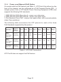
3.1.4
Power over Ethernet (PoE) Option
On models with the PoE feature (see Table 1), UTP Port A (the left port on the
front of the chassis) can be configured as a PoE Powered Device (PD). It
accepts power from a UTP-based Power Sourcing Equipment (PSE) and
supports the following PoE standards:
1. IEEE 802.3af-2003 Alternative A – power over data wires
2. IEEE 802.3af-2003 Alternative B – power over spare wires
3. Pre-Standard Cisco PoE – power over spare wires, with reversed polarity
(older Cisco switches)
The following table summarizes the UTP pinouts for each of the three
PoE Standards supported by this product.
Standard
Source
Voltage
Pin 1
Pin 2
Pin 3
Pin 4
Pin 5
Pin 6
Pin 7
Pin 8
IEEE
802.af
using data
pairs (A)
48 V D C
protected
RX,
DC+
RX,
DC+
TX,
DC-
Spare
Spare
TX,
DC-
Spare
Spare
IEEE
802.af
using spare
pairs (B)
48 V D C
protected
RX
RX
TX
DC+
DC+
TX
DC-
DC-
Pre-Standard Cisco
48 V D C
protected
RX
RX
TX
DC-
DC-
TX
DC+
DC+
Table 2: UTP PoE Connections
UTP Port B does not support the PoE feature.
Page 10
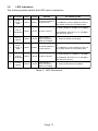
3.2
LED Indicators
The following table details the LED status indicators:
LED
Function
Color
Legend
Off State
On / Blinking state
Solid: Power applied to power source 1
1
Power
Supply 1
LED
Green
PWR1
2
Port A
Link/Activity
Green
Lnk/Act No link on Port A
3
Port A
Speed
Green
10/100
If Port A link is
active, the port is
linked at 10 Mbps
4
Power
Supply 2
LED
Green
PWR2
No power applied to
0.5 Hz Blinking: Power applied to source 2
power source 2
and contact closure is in the alarm state
5
Port B
Link/Activity
Green
Lnk/Act No link on Port B
6
Port B
Speed
Green
10/100
No power applied to
power source 1
0.5 Hz Blinking: Power applied to source 1
and contact closure is in the alarm state
On: UTP A linked at 10 Mbps or 100 Mbps
10 Hz Blinking: Rx and Tx 10 or 100 Mbps
data activity on Port A
On: UTP Port linked at 100 Mbps
Solid: Power applied to power source 2
On: UTP B linked at 10 Mbps or 100 Mbps
If Port B link is
active, the port is
linked at 10 Mbps
10 Hz Blinking: Rx and Tx 10 or 100 Mbps
data activity on Port B
On: UTP Port B linked at 100 Mbps
Table 3: LED Definitions
Page 11
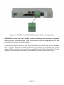
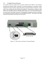
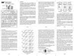
3.3
Contact Closure Sensors
On models with the contact closure sensor feature (see Table 1), the chassis
provides an optional 8-pin connector (4 contact sensors) on the back of the
chassis that can be used to sense the state of external alarm conditions. Each
of the four sensor pins can detect if the wired circuit is open or closed, or has
high or low voltage from the external equipment. A DIP-switch located on the
back of the chassis enables or disables alarm reporting. If no external equipment
is connected to the 8-pin connector, it is important to disable the alarm reporting
by configuring each DIP-switch to the DISABLE position. See Figure 5 for the
location of the switch and terminal connector.
Enable
Alarms
+ Rt + Rt + Rt + Rt
1
1234
Disable
2
3
4
Figure 5: DIP-switch and Alarm Terminal Details
Page 12
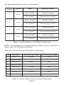
The table describes the function of each switch.
DIP-Sw itch
Position
Function
1
Alarm 1
2
3
4
State
Reporting Indication
Down = Disabled
No alarm reporting
Up = Enabled
Front panel alarm indication
Down = Disabled
No alarm reporting
Up = Enabled
Front panel alarm indication
Down = Disabled
No alarm reporting
Up = Enabled
Front panel alarm indication
Down = Disabled
No alarm reporting
Up = Enabled
Front panel alarm indication
Alarm 2
Alarm 3
Alarm 4
Table 4: Contact Sensors - DIP-switch Configuration
NOTE: Not all chassis are equipped with the contact sensors. Internally, all
signal return (“Rt”) pins are connected.
The 8-pin connector has the following pin configuration:
Pin#
Description
Closed Circuit (low voltage)
Open Circuit (high voltage)
1
Sensor 1 ("+")
No Alarm
Alarm
2
Signal Return ("Rt")
3
Sensor 2 ("+")
No Alarm
Alarm
4
Signal Return ("Rt")
5
Sensor 3 ("+")
No Alarm
Alarm
6
Signal Return ("Rt")
7
Sensor 4 ("+")
No Alarm
Alarm
8
Signal Return ("Rt")
Table 5: Contact Closure Sensors Pinout Configuration
Page 13
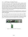
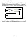
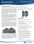
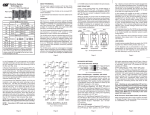
3.4
Ethernet Backplane
The chassis contains two Ethernet backplane buses (A and B) that operate at
10/100Mbps. Both buses are enabled by default. When an iConverter module
that features Ethernet backplane connectivity is installed in the chassis, the A
bus connects directly to UTP Port A, and the B bus connects directly to UTP
Port B as shown in Figure 6.
Inserted Module
Port 1
Port 2
Backplane B
Ethernet
Switch
Backplane A
UTP
Port A
UTP
Port B
Figure 6: Backplane Connectivity
The data traversing across the Ethernet backplane can be controlled by
configuring the installed iConverter module. See the specific iConverter module’s
User Manual for additional details.
Page 14
4.0
CHASSIS MANAGEMENT
4.1
Overview
The 1-Module Redundant chassis features configurable options and status
information depending on the model. Configurable parameters and status
information available through the serial console port on the installed iConverter
Management Module are:
•
•
•
•
•
Contact Closure Alarm notification - Enable/disable (physical DIP-switches)
Port A/B Control - UTP auto-negotiation, 10/100 and Full/Half-Duplex
Pause Control - Enable/disable
Port Access Control - Enable/disable
Power Supply 1/2 - Voltage, current and temperature
4.1.1
Configuring and Monitoring the Chassis
Remote configuration of the chassis is provided by installing an iConverter
Management Module such as a 10/100M. To configure, attach the Management
Module to a RS-232 equipped computer with terminal emulation software such
as HyperTerminal. The Management Module Serial Console Port (DCE) is a
mini DIN-6 female connector which can be changed to a DB-9 connector with
the adapter included with the module (Part #8082-0). Attach the ends of serial
cable to the serial port of the PC and the Serial Console Port of the Management
Module. This is a standard asynchronous serial interface
Start HyperTerminal and select the correct COM Port in the HyperTerminal
“Connect To:” window.
Set the PC’s serial port to the following:
Bits Per Second
Stop Bits
Data Bits
Parity
Hardware Flow Control
57,600
1
8
NONE
NONE
Page 15
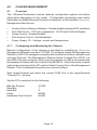
Power the chassis containing the Management Module and press <ENTER>
to bring up a command line prompt on the attached PC.
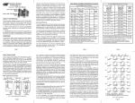
The Management Options screen will be displayed.
Management Options
iConverter, Serial Agent
Network Management
1: Chassis and Module Management
2: Set Module Identifier
Management Module Preferences
3: IP and Control Preferences
4: SNMP Preferences
5: Abandon Preference Changes
6: Save Preference Changes
7: Restore to Factory Defaults
8: Restart Management Module
9: Other Networking Features
Management Module Maintenance
10: Firmware Update
11: Set Date/Time
IP Address
= 192.168.1.220
Chassis Number = 1
Enter Choice, (H)elp, E(x)it >
Figure 7: Management Option Screen
A new Management Module does not have a password, and will skip the
Password Entry screen and go straight to the Management Options screen.
Page 16
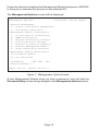
If a password has been set, the Password Entry screen will be displayed.
Type the password and press <ENTER>, the Management Options screen
will be displayed.
Omnitron Systems Technology, Inc.
Copyright 2001-2007 OST, Inc.
Password Entry
iConverter, Serial Agent
----------------------------------------------------------Omnitron Systems Technology
Technical Support:
(949) 250-6510
140 Technology #500
Sales/Products: (800) 675-8410
Irvine, CA 92618
On the web at:
www.omnitron-systems.com
----------------------------------------------------------IP Address
192.168.1.220
MAC 00:00:00:00:00:00
[xxxxxxxx]
Please enter the password >
Figure 8: Password Screen
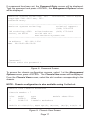
To access the chassis configuration screens, select 1 at the Management
Options screen, press <ENTER>. The Chassis View screen will be displayed.
From the Chassis View screen, select the slot number corresponding to the
chassis.
NOTE: Chassis configuration is also available using NetOutlook.
Chassis View 1-Module Redundant
Chassis Number = 7
Slot
1
2
Model
8959-0
8248-512
Type
Module Identifier
2FXM
1-Module Redundant
Module to View(1-2), Mgmt Opt(0),(R)eset, (H)elp, E(x)it >2
Figure 9: Chassis View Screen
Page 17
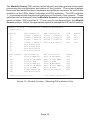
The Module Screen (DIP-switch control shown) provides general information
concerning the configuration and status of the module. The screen displays
the model and serial numbers, hardware and software revisions, as well as the
condition of the LEDs, Alarm Indicators and DIP-switches. The DIP-switches
1 - 4 correspond with the physical switches on the back of the chassis. These
switches can be changed from the Module Screen by selecting the appropriate
switch number. DIP-switches 9 - 15 can only by configured from the Module
Screen options. Select the appropriate option to change the DIP-switch setting.
Module Screen - iConverter 1-Module Redundant
Identifier Switch
1:
2:
3:
4:
5:
6:
7:
8:
ON Condition
Alarm 1 Enable
Alarm 2 Enable
Alarm 3 Enable
Alarm 4 Enable
Not Available
Not Available
Not Available
Not Available
OFF Condition
Alarm 1 Disable
Alarm 2 Disable
Alarm 3 Disable
Alarm 4 Disable
H/W
On
Off
Off
Off
Soft Switch
9:
10:
11:
12:
13:
14:
15:
16:
ON Condition
Port A Manual
Port A 10 Mbps
Port A HDX
Port B Manual
Port B 10 Mbps
Port B HDX
Pause Enabled
Not Available
Off Condition
Port A AN Mode
Port A 100 Mbps
Port A FDX
Port B AN Mode
Port B 100 Mbps
Port B FDX
Pause Disabled
State
Off
Off
Off
Off
Off
Off
Off
Toggle Switch(1-16), ....... (S)tatus, Port(C)tl >
Figure 10: Module Screen - Showing DIP-switches Only
Page 18
Actual
On
Off
Off
Off
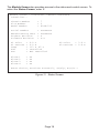
The Module Screen also provides access to the status and control screen. To
select the Status Screen, enter S.
Module Screen - iConverter 1-Module Redundant
Identifier Chassis Number
Slot Number
Model Number
= 7
= 2
= 8248-512
Serial Number
Manufacturing Date
Product Revision
Software Revision
=
=
=
=
xxxxxxxx
xxxxxxxx
x
x.x
P1 Volts
P1 Current
Temp
PoE
Fan
=
=
=
=
=
0.0 V
0.0 A
113 F 45 C
Installed
Not Installed
Alarm
Alarm
Alarm
Alarm
=
=
=
=
On
On
On
On
1
2
3
4
P2 Volts
P2 Current
= 3.6 V
= 0.9 A
Enter Choice, Previous Screen(0), (H)elp, E(x)it >
Figure 11: Status Screen
Page 19
For models with UTP ports, the Control Screen is available to enable or disable
Port A and Port B. To select the Control Screen, enter C.
Module Screen - iConverter 1-Module Redundant
Identifier Chassis Number
Slot Number
Model Number
=
=
=
7
2
8248-512
Port Access Control Setup
------------------------1: Port A Enable
On
2: Port B Enable
On
Port VLAN Path Setup
-------------------3: Port A to Backplane
4: Port A to Backplane
5: Port B to Backplane
6: Port B to Backplane
7: Port A to Port B
A
B
A
B
On
Off
Off
On
Off
Enter Choice, Previous Screen(0), (H)elp, E(x)it >
Figure 12: Control Screen
Page 20
5.0
APPLICATIONS
5.1
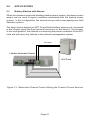
Battery Backup with Alarms
When the chassis is used with a battery backup power system, the alarm contact
sensor can be used to report conditions associated with the backup power
system. In this configuration, the chassis can provide a managed power fault
detection system.
The figure below depicts an APC PowerShield battery backup unit connected
to the chassis using the 8-pin terminal connector on the back of the chassis,
In this configuration, the chassis is monitoring the power conditions of the APC
units and will report any failures to the network management system.
DC Power
1-Module Redundant Chassis
APC PowerShield
Alarm indicators
Figure 13: Redundant Chassis Power Utilizing the Contact Closure Sensors
Page 21
The four sensors are compatible with APC PowerShield product. The table
below defines the pinouts for both units.
APC
Pin #
iConverter
Chassis
Pin #
Description
Closed Circuit
Open Circuit
3
2
Signal Return
N/A
N/A
4
1
Power Source
Utility Power
Battery Power
5
3
Battery Reserve
Battery Full-Charged
Battery Fails Self-Test
6
5
Battery Condition
Battery Present
Battery Missing
7
7
Low Battery
Battery Near Capacity
Battery <20% Capacity
Table 6: APC PowerShield Alarm Contact Configuration
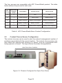
5.2
Contact Closure Sensor Configuration
The contact closures can be used to alert the network management system of
problems associated with the remote location. The contact closure sensor can
also detect the opening and closing of a switch, such as a equipment door
being opened or closed. The figure below illustrates this application.
Open Door Alarm Condition
Figure 14: Chassis Configured for Open Door Alarm
Page 22
6.0
SPECIFICATIONS
Description
iConverter 1-Module Redundant-Power Chassis
Ports
Protocols
2 x RJ-45
10Base-T, 100Base-Tx with 1536 max. frame size
Cable Types
UTP
EIA/TIA 568A/568B
Connector Types
UTP
Contact Closure Sensors
RJ-45
Field-wireable 16-24 AWG
Power Requirements
Low Voltage DC Power
9 - 24 VDC
1.5A @ 9.0VDC
Low Voltage DC Power
Connector
2.5mm Barrel Connector or Field-wireable 16-20 AWG Terminal Connector
High Voltage DC Power
+24 to +60 VDC
or
-24 to -60 VDC
0.3A @ 48VDC
High Voltage DC Power
Connector
Field-wireable 16-20 AWG Terminal Connector
PoE Power
PoE Connector
AC Power Adapter [US]
AC Power Adapter [Universal]
Dimensions
+44 to +57 VDC
or
-44 to -57 VDC
0.27A @ 48VDC
RJ-45 IEEE 802.3af-2003 Alternative A & B,
Pre-standard Cisco PoE
100-120 VAC, 60Hz
0.2A @ 120VAC
100-240 VAC, 50-60 Hz
0.2A @ 120VAC
5.4" (W) x 6.8" (L) x 1.0" (H)
Weight
without power adapter
1.5 lbs.
with power adapter
2.0 lbs.
Compliance
UL, CE, FCC, AS/NZS 3548, & VCCI Class A
Temperature
Operational - Commercial
0 to +50oC
Operational - Wide Range
-40 to +60oC
Storage
-40 to +80oC
Humidity (non-condensing)
5 to 95%
Altitude
-100m to 4000m
MTBF [hrs]
without power adapter
540,000
with US power adapter
250,000
with Univ. power adapter
100,000
Table 7: Model Specifications
Refer to Table 1 for applicable product features.
Page 23
Warning
The operating description in this Instruction Manual is for use by qualified
personnel only. To avoid electrical shock, do not perform any servicing of this
unit other than that contained in the operating instructions, unless you are
qualified and certified to do so by Omnitron Systems Technology, Inc.
Caution
All user-required operations can be performed without opening the unit. Never
attempt to open or remove the cover or tamper with the unit. There are no user
replaceable or serviceable parts in this unit. Equipment is not intended to be
installed and used in a place (home, school, or public area) accessible to the
general population.
Page 24
Warranty
This product is warranted to the original purchaser against defects in material
and workmanship for a period of TWO YEARS from the date of shipment. A
LIFETIME warranty may be obtained by the original purchaser by REGISTERING
this product with Omnitron within 90 days from the date of shipment. TO
REGISTER, COMPLETE AND MAIL OR FAX THE ENCLOSED
REGISTRATION FORM. Or you may register your product on the Internet at
http://www.omnitron-systems.com. During the warranty period, Omnitron will,
at its option, repair or replace a product which is proven to be defective.
For warranty service, the product must be sent to an Omnitron designated
facility, at Buyer’s expense. Omnitron will pay the shipping charge to return the
product to Buyer’s designated US address using Omnitron’s standard shipping
method.
Limitation of Warranty
The foregoing warranty shall not apply to defects resulting from improper or
inadequate use and/or maintenance of the equipment by Buyer, Buyersupplied equipment, Buyer-supplied interfacing, unauthorized modifications or
tampering with equipment (including removal of equipment cover by personnel
not specifically authorized and certified by Omnitron), or misuse, or operating
outside the environmental specification of the product (including but not limited
to voltage, ambient temperature, radiation, unusual dust, etc.), or improper site
preparation or maintenance.
No other warranty is expressed or implied. Omnitron specifically disclaims the
implied warranties of merchantability and fitness for any particular purpose.
Exclusive Remedies
The remedies provided herein are the Buyer’s sole and exclusive remedies.
Omnitron shall not be liable for any direct, indirect, special, incidental, or
consequential damages, whether based on contract, tort, or any legal theory.
Page 25
7.0
TECHNICAL SUPPORT
If you encounter problems with this product, contact Omnitron Technical
Support.
Phone:
+1 800-675-8410
+1 949-250-6510
USA
Fax:
949-250-6514
Address:
Omnitron Systems Technology, Inc.
140 Technology Dr., #500
Irvine, CA 92618
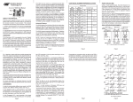
Email:
URL:
[email protected]
http://www.omnitron-systems.com
Form 040-8245-001D 10/07
Page 26