1
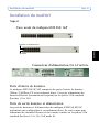
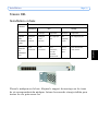
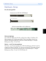
ENGLISH
DEUTSCH
ITALIANO
User’s Manual
FRANCAIS
AXIS PoE MIDSPAN 8-Port /
AXIS PoE Midspan 16-Port
ESPAÑOL
About this Document
This manual includes instructions for using and
managing the AXIS PoE MIDSPAN 8-Port/ AXIS PoE
Midspan 16-Port on your network. Later versions of
this document will be posted to the Axis Website.
pursuant to Subpart B of Part 15 of FCC rules, which are
designed to provide reasonable protection against such
interference when operated in a commercial environment.
Operation of this equipment in a residential area is likely
to cause interference, in which case the user at his/her
own expense will be required to take measures required
to correct the interference.
Safety Notices Used In This
Manual
Canada. This Class B digital apparatus complies with
Canadian ICES-003.
Caution! - Indicates a potential hazard that can
damage the product.
Europe.
Important! - Indicates a hazard that can seriously
impair operation.
Do not proceed beyond any of the above notices until
you have fully understood the implications.
Intellectual Property Rights
Axis AB has intellectual property rights relating to
technology embodied in the product described in this
document. In particular, and without limitation, these
intellectual property rights may include one or more of
the patents listed at http://www.axis.com/patent.htm
and one or more additional patents or pending patent
applications in the US and other countries.
Electromagnetic Compatibility
(EMC)
This equipment generates, uses and can radiate radio
frequency energy and, if not installed and used in
accordance with the instructions, may cause harmful
interference to radio communications. However, there
is no guarantee that interference will not occur in a
particular installation.
This digital equipment fulfills the
requirements for radiated emission according to limit B
of EN55022/1998, and the requirements for immunity
according to EN55024/1998 residential, commercial, and
light industry.
Japan. This is a class B product based on the standard
of the Voluntary Control Council for Interference from
Information Technology Equipment (VCCI). If this is
used near a radio or television receiver in a domestic
environment, it may cause radio interference. Install and
use the equipment according to the instruction manual.
Australia. This electronic device meets the
requirements of the Radio communications
(Electromagnetic Compatibility) Standard AS/NZS
CISPR22:2002.
Equipment Modifications
This equipment must be installed and used in strict
accordance with the instructions given in the user
documentation. This equipment contains no
user-serviceable components. Unauthorized equipment
changes or modifications will invalidate all applicable
regulatory certifications and approvals.
Consult your dealer or an experienced radio/TV
technician for help.
Every care has been taken in the preparation of this
manual. Please inform your local Axis office of any
inaccuracy or omission. Axis Communications AB
cannot be held responsible for any technical or
typographical errors and reserves the right to make
changes to the product and manuals without prior notice.
Axis Communications AB makes no warranty of any
kind with regard to the material contained within this
document, including, but not limited to, the implied
warranties of merchantability and fitness for a particular
purpose. Axis Communications AB shall not be liable nor
responsible for incidental or consequential damages in
connection with the furnishing, performance or use of
this material.
Shielded (STP) network cables must be used with this
unit to ensure compliance with EMC standards.
Support
If this equipment does cause harmful interference to
radio or television reception, which can be determined
by turning the equipment off and on, the user is
encouraged to try to correct the interference by one or
more of the following measures:
Re-orient or relocate the receiving antenna.
Increase the separation between the equipment and
receiver.
Connect the equipment to an outlet on a different
circuit to the receiver.
USA. This equipment has been tested and found to
comply with the limits for a Class B computing device
Should you require any technical assistance, please
contact your Axis reseller. If your questions cannot be
answered immediately, the reseller will forward your
queries through the appropriate channels to ensure a
rapid response. If you are connected to the Internet,
you can:
• Download user documentation and firmware
updates
• Find answers to resolved problems in the FAQ
database
• Search by product, category, or phrases
• Report problems to Axis support by logging in to
your private support area
• Visit Axis Support at www.axis.com/techsup/
RoHS
This product complies with both the European
RoHS directive, 2002/95/EC, and the Chinese
RoHS regulations, ACPEIP.
WEEE Directive
The European Union has enacted a Directive
2002/96/EC on Waste Electrical and
Electronic Equipment (WEEE Directive).
This directive is applicable in the European
Union member states.
The WEEE marking on this product or its
documentation indicates that the product must not be
disposed of together with household waste. To prevent
possible harm to human health and/or the environment,
the product must be disposed of in an approved and
environmentally safe recycling process. For further
information on how to dispose of this product
correctly, contact the product supplier, or the local
authority responsible for waste disposal in your area.
Business users should contact the product supplier for
information on how to dispose of this product
correctly. This product should not be mixed with other
commercial waste.
AXIS PoE MIDSPAN 8-Port/AXIS PoE Midspan
16-Port is identical to the Phihong
PoE370U-480-8/PoE370U-480-16.
AXIS PoE MIDSPAN 8-Port/ AXIS PoE Midspan
16-Port User’s Manual Rev.1.0
Dated: December 2007
Part No: 30081
Copyright© Axis Communications AB, 2007
Package Contents
Page 5
Package Contents
PoE Midspan
Mains cable
Two 19-inch rack mounting brackets
Four M4 x 8mm Philips flat head screws
AXIS warranty statement
Four rubber feet
Manual
ENGLISH
ENGLISH
•
•
•
•
•
•
•
Page 6
Safety Information
Safety Information
Please read the following carefully before installing and connecting the
system to a power source.
Note: Only qualified and trained service personnel (in accordance with IEC 60950 and AS/NZS
3260) should install, replace, or service the equipment. Install the system in accordance
with Country, National, or the U.S. National Electric Code if you are in the United
States.
Precautions
1. The building where this product is used requires a fuse or circuit
breaker no larger than 15 A for 120 VAC (U.S.A.) or 10 A, 230 VAC
(international). The building facility must protect the AXIS PoE
Midspans 8P/16P from over current or short-circuits.
2. Read the Midspan Hardware Setup procedure before connecting
the AXIS PoE Midspans 8P/16P to a power source (including
power cord requirements).
3. Do not operate the product in an area that exceeds the maximum
recommended ambient temperature of 104 ºF/ 40 ºC to avoid
overheating the AXIS PoE Midspans 8P/16P. Allow at least 3 to 4
inches/ 7.6 to 10.2 cm clearance around all ventilation openings.
4. Do not stack the chassis on any other equipment to support its
weight. Shelf mounted equipment requires a stable and durable
surface. Do not push or pull on the Midspan while installing.
5. The AXIS PoE Midspans 8P/16P consists of two rows of "Data”
and "Data & Power" ports. The ports use RJ-45 data sockets.
Connect only RJ-45 data cables to these sockets. Do not connect
telephone cables into these ports.
6. Do not work on the AXIS PoE Midspans 8P/16P system or connect
or disconnect cables, when there is lightning.
7. The AC or DC plug/socket combination must be accessible at all
times, as it is the main disconnect device to the product.
Safety Information
Page 7
8. Before servicing the product, always disconnect the product from
its AC source.
9. Abide by appropriate National laws and regulations when it comes
to discarding this product.
ENGLISH
ENGLISH
Page 8
Safety Information
Power Cord Requirements
Power cords must meet the requirements for the country they are used in.
USA and Canada
•
The cord must have a minimum of 10A rated current competence.
•
The cord must be CSA or UL approved.
•
The minimum requirement for the flexible cord is:
• 18 AWG (10A)
• Three-conductor (line, neutral, ground)
• Type SV (Stranded Vacuum Rubber Jacketed) or SJ (Stranded Junior Rubber
Jacketed) or SVT (Stranded Vacuum Rubber Jacketed Themoplastic) or SJT
(Stranded Junior Themoplastic)
• The plug must be earth-grounded with a NEMA 5-15P (15A, 125 V) or
NEMA 6-15P (15A, 250 V) configuration.
Europe and South America Switzerland: The supply plug must comply with SEV/ASE 1011.
Denmark: The supply plug must comply with section 107-2-D1, standard DK2-1a
or DK2-5a.
United Kingdom: The Midspan is covered by General Approval (section 16.16.060),
NS/G/12345/J100003, for indirect connection to a public telecommunication system
France and Peru: IT equipment cannot power this device. In the case of an IT powered device, the unit needs to be powered by 230 V through an isolation transformer with a ratio of 1:1 and the secondary connection (Neutral) is properly
grounded.
• The Midspan must have access to a power outlet. Disconnect the power
cord from the outlet, to eliminate power from the device.
• The flexible cord that connects to the Midspan must have a configuration to connect with an EN60320/IEC320 inlet connector.
• According to the EN60950/IEC 950 specifications, this device functions
under SELV (Safety Extra Low Voltage) conditions. The conditions are
true if the equipment and the connected device functions under SELV
conditions.
• The AXIS PoE Midspans 8P/16P meet the UL/
cUL per EN60950 safety standard. This is displayed in the back side of the product.
Hardware Setup
Page 9
Hardware Setup
Appearance
Front side of AXIS PoE 16P Midspan
ENGLISH
ENGLISH
Data and Power
Data
AC Power Connector at the back
Data Input Ports
The AXIS PoE Midspans 8P/16P have 10Base-T/100Base-TX data input
ports, that have straight-wired configuration. These ports carry Ethernet
data (Tx/Rx) over the standard 2-wire pairs (pins 1/2 and 3/6).
Data and Power Output Ports
The AXIS PoE Midspans 8P/16P Data and Power ports have straight-wire
configuration. They are designed to carry Ethernet data and DC power over
the standard 2-wire pairs (pins 1/2 and 3/6; PoE mode A).
Page 10
Installation
Installation
Connecting Power Cables
The AC power cable is connected to the AC power connector located in the
rear side of the AXIS PoE Midspans 8P/16P and the power outlet.
Connecting Ethernet Cables
The ports in the product’s front panel are configured as ‘route through’
ports for all the eight/ sixteen RJ-45 connectors. Use Category 5 cabling in
making connections.
1. Connect cables from the ethernet switch to the data ports - on the
bottom row of the AXIS PoE Midspans 8P/16P.
2. Connect the cables from the IEEE 802.3af powered devices to the
corresponding Data and Power ports on the top row of the AXIS
PoE Midspans 8P/16P.
Powering Up
AXIS PoE Midspans 8P/16P are powered by the power cord. In order to
apply or remove power to or from the Midspan, connect or disconnect the
AC power cable to or from the AC power connector on the rear side of the
unit.
With AC power the unit starts-up and the internal fans are active. The
device runs through a quick power-on test, which takes less than 10
seconds. During this period, all ports are initially disabled and the port
indicators light up. The sequence of the port LEDs are shown in the section
below - LED Indicator. Ports now operate under normal conditions.
Installation
Page 11
LED Indicator
Conditions
Indicator
s
Power
LED
Green
Orange
static
blinking
static
blinking
Midspan
not powered
Midspan
powered
n/a
n/a
n/a
Port disabled
Port connected
Port connected; data
port disconnected
Port has
an error
Port is disconnected,
but enabled
Rack-Mounting Installation
Position the Midspan on the rack. Arrange the mounting bracket to the
corresponding screw holes in the Midspan. Keep the screw area visible to
insert screws, and then tighten them.
ENGLISH
ENGLISH
Data &
Power
Off
Page 12
Technical Specifications
Technical Specifications
Parameters
Specifications
Mechanical Specifications
Dimensions
17.25 inch (438 mm) length
8.98 inch (228 mm) width
1.75 inch (44.5 mm) height
9lbs (4.08 Kg) weight
Environmental Specifications
Temperature
Operating: 32°F to 104°F (0°C to +40°C)
Non-Operating: -77°F to 149°F (-25°C to +65°C)
Relative Humidity
Operating: 5% to 90%
Non-Operating: 5% to 90%
Maximum heat dissipation of the AXIS PoE Midspans 8P/16P
AC mode =125W
Electrical Specifications
AC Input voltage rating
100VAC to 240VAC
AC Input voltage range
90VAC to 264VAC
AC Input current
5.5A (rms) at Max. load
AC Input frequency
47Hz to 63H
Max. In-rush current
30A for 115VAC at Max. load
60A for 230VAC at Max. load
AC Output voltage
480: 50VDC
56VDC: 56VDC
Max. load current
480: 0.32A
56VDC: 0.275A
Output Power, per port
15.4W (not to exceed total output power)
Total Output Power
No. of ports: 8 - 125W max, 16 - 250W max
Nominal Output Voltage
44VDC to 57VDC
Approvals
•
cUL/UL
•
TUV
•
CE
Troubleshooting
Page 13
Troubleshooting
If problems occur with the Midspan, please refer to the table below. The
troubleshooting solutions provided can only solve minor problems. If your
problem is not listed, please contact our local office for further technical
assistance.
Possible Solutions
Midspan does not power up
1. Ensure that AC power cord is connected.
2. Ensure that AC power cord is in good condition.
3. If neither of the above is the problem, disconnect
the AC power cord and reconnect. Observe Port LEDs
to verify proper power up.
AC LED unlit
Verify if the Midspan is properly connected to an AC
power source.
Data and Power Port LED do not light 'green'
Ensure Ports are connected to a Network.
Verify the following:
1. Power is applied to the Midspan
2. Network Ethernet cable is connected to the Data
port
3. Powered device Ethernet cable is connected to the
Data & Power port
4. The right kind of Ethernet cable is used; do not use
crossover-type Ethernet cable
5. Cable pairs are connected to corresponding ports.
ENGLISH
ENGLISH
Problem
Page 14
Troubleshooting
Contenu de l'emballage
Page 15
Contenu de l'emballage
•
•
•
•
•
•
•
Midspan PoE
Câble secteur
Deux supports de montage en baie de 19 pouces
Quatre vis à tête plate Philips M4 x 8 mm
Déclaration de garantie AXIS
4 pieds en caoutchouc
Manuel
FRANCAIS
Page 16
Informations de sécurité
Informations de sécurité
Veuillez lire attentivement les informations qui suivent avant d'installer et
de connecter le système à une source d'alimentation.
Remarque : Seul le personnel de maintenance qualifié et formé (conformément aux normes
IEC 60950 et AS/NZS 3260) est autorisé à installer, remplacer ou dépanner le matériel.
Installez le système conformément aux procédures en vigueur dans votre pays, ou au
U.S. National Electric Code si vous êtes aux États-Unis.
Précautions
1. Le bâtiment dans lequel ce produit doit être utilisé doit être muni
d'un fusible ou d'un disjoncteur n'excédant pas 15 A pour 120 Vca
(États-Unis) ou 10 A pour 230 Vca (international). L'installation du
bâtiment doit protéger le midspan AXIS PoE 8P/16P des
surtensions et des courts-circuits.
2. Consultez la procédure d'installation du matériel avant de
connecter le midspan AXIS PoE 8P/16P à une source
d'alimentation (notamment les conditions relatives au câble
d'alimentation).
3. N'utilisez pas le produit dans un local dépassant la température
ambiante maximale recommandée de 40 °C/104 °F, afin d'éviter la
surchauffe du midspan AXIS PoE 8P/16P. Prévoyez un
dégagement d'au moins 7,6 à 10,2 cm (3 à 4 pouces) au niveau de
tous les évents.
4. N'empilez pas le châssis sur d'autres appareils afin d'en soutenir le
poids. L'équipement monté sur étagère nécessite une surface stable
et résistante. Ne poussez pas ou ne tirez pas sur le midspan
pendant que vous l'installez.
5. Le midspan AXIS PoE 8P/16P comporte deux rangées de ports «
Données » et « Données & Alimentation ». Ces ports utilisent des
connecteurs de données RJ-45. Ne connectez pas de câbles
téléphoniques à ces ports. Connectez-y uniquement des câbles de
données RJ-45.
6. Ne travaillez pas sur le système midspan AXIS PoE 8P/16P et ne
connectez ou ne déconnectez aucun câble en cas d'orage.
Informations de sécurité
Page 17
7. La combinaison fiche/prise CA ou CC doit être accessible à tout
moment, car elle constitue le principal dispositif de déconnexion
du produit.
8. Avant toute intervention sur le produit, débranchez-le toujours de
sa source de CA.
9. Adhérez à la réglementation nationale appropriée pour la mise au
rebut du produit.
FRANCAIS
Informations de sécurité
Page 18
Conditions requises pour les câbles d'alimentation
Les câbles d'alimentation doivent être conformes aux conditions requises
par le pays dans lequel ils sont utilisés.
États-Unis et
Canada
•
Le câble doit supporter au minimum une intensité nominale de 10 A.
•
Le câble doit être agréé CSA ou UL.
•
Les conditions minimales suivantes sont requises pour le câble flexible :
• 18 AWG (10 A)
• Trois conducteurs (phase, neutre, terre)
• Type SV (Stranded Vacuum Rubber Jacketed), SJ (Stranded Junior Rubber
Jacketed), SVT (Stranded Vacuum Rubber Jacketed Themoplastic) ou SJT
(Stranded Junior Themoplastic)
• "La prise doit être mise à la terre avec une configuration NEMA 5-15P (15 A,
125 V) ou NEMA 6-15P (15 A, 250 V).
Europe et Amérique Suisse : la prise d'alimentation doit être conforme à la norme SEV/ASE 1011.
du Sud
Danemark : la prise d'alimentation doit être conforme à la section 107-2-D1 de la
norme DK2-1a ou DK2-5a.
Royaume-Uni : La réglementation relative au midspan est traitée dans le General
Approval (section 16.16.060) NS/G/12345/J100003 sur les connexions indirectes à un
système de télécommunications publiques.
France et Pérou : Aucun matériel informatique ne peut alimenter cet appareil. Dans le
cas d'un appareil alimenté par un système informatique, l'unité doit être alimentée à
230 V par l'intermédiaire d'un transformateur de séparation présentant un rapport de
1:1 et la connexion secondaire (Neutre) doit bénéficier d'une mise à la terre correcte.
• Le midspan doit avoir accès à une prise de courant. Débranchez le câble
d'alimentation de la prise pour couper l'alimentation de l'appareil.
• Le câble flexible qui se connecte au midspan doit présenter une
configuration appropriée à un branchement sur un connecteur d'entrée
EN60320/IEC320.
• Selon les spécifications de la norme EN60950/IEC 950, cet appareil
fonctionne dans des conditions SELV (Safety Extra Low Voltage). Ces
conditions sont remplies si l'équipement et l'appareil connecté
fonctionnent dans des conditions SELV.
• Le midspan AXIS PoE 8P/16P est conforme UL/cUL selon la norme de
sécurité EN60950. Ces informations apparaissent à l'arrière du produit.
Installation du matériel
Page 19
Installation du matériel
Aspect
Face avant du midspan AXIS PoE 16P
Données et alimentation
FRANCAIS
Données
Connecteur d'alimentation CA à l'arrière
Ports d'entrée de données
Le midspan AXIS PoE 8P/16P comporte des ports d'entrée de données
10Base-T/100Base-TX à raccordement direct. Ces ports acheminent des
données Ethernet (transmission/réception) sur les paires 2 fils standard
(broches 1/2 et 3/6).
Ports de sortie données et alimentation
Les ports de données et d'alimentation du midspan AXIS PoE 8P/16P
présentent une configuration à raccordement direct. Ils sont conçus pour
acheminer des données Ethernet et du courant continu sur les paires 2 fils
standard (broches 1/2 et 3/6 ; PoE mode A).
Page 20
Installation
Installation
Connexion des câbles d'alimentation
Le câble d'alimentation CA se branche sur le connecteur d'alimentation CA
situé sur la face arrière du midspan AXIS PoE 8P/16P et sur la prise de
courant.
Connexion des câbles Ethernet
Les ports présents sur le panneau avant du produit sont configurés en tant
que ports d'acheminement pour l'ensemble des huit/seize connecteurs RJ45. Utilisez des câbles de catégorie 5 pour établir les connexions.
1. Connectez les câbles entre le commutateur Ethernet et les ports de
données, dans la rangée inférieure du midspan AXIS PoE 8P/16P.
2. Connectez les câbles entre les appareils IEEE 802.3af et les ports de
données et d'alimentation correspondants, dans la rangée
supérieure du midspan AXIS PoE 8P/16P.
Mise sous tension
Le midspan AXIS PoE 8P/16P est alimenté par le câble secteur. Pour mettre
le midspan sous tension ou hors tension, branchez le câble d'alimentation
CA sur le connecteur CA situé à l'arrière de l'unité ou débranchez-le.
Dès qu'elle est alimentée en CA, l'unité démarre et les ventilateurs internes
s'activent. L'appareil procède à un bref test à la mise sous tension, qui dure
moins de dix secondes. Pendant cette période, les ports sont désactivés et
leurs témoins lumineux s'allument. La séquence des témoins DEL des ports
est fournie dans la section ci-dessous - Témoin DEL. Les ports fonctionnent
ensuite dans des conditions normales.
Installation
Page 21
Témoin DEL
Installation en baie
Conditions
Témoins
Témoin
DEL
d'aliment
ation
Vert
Orange
statique
clignotant
statique
clignotant
Midspan
hors
tension
Midspan
sous
tension
Ne s'applique
pas
Ne
s'appliqu
e pas
Ne s'applique pas
Port
désactivé
Port
connecté
Port
connecté ;
port de
données
déconnecté
Erreur
sur le
port
Port déconnecté,
mais activé
Placez le midspan sur la baie. Alignez le support de montage sur les trous
de vis correspondants du midspan. Laissez les zones de vissage visibles pour
insérer les vis, puis serrez-les.
FRANCAIS
Données
et
alimentat
ion
Désactivé
Caractéristiques techniques
Page 22
Caractéristiques techniques
Paramètres
Spécifications
Spécifications mécaniques
Dimensions
Longueur 438 mm (17,25 pouces)
Largeur 228 mm (8,98 pouces)
Hauteur 44,5 mm (1,75 pouce)
Poids 4,08 kg (9 livres)
Spécifications d'environnement
Température
Sous tension : de 0 à 40 °C (de 32 à 104 °F)
Hors tension : de -25 à +65 °C (de -77 à 149 °F)
Humidité relative
Sous tension : de 5 à 90 %
Hors tension : de 5 à 90 %
Dissipation maximale de chaleur du
Mode CA =125 W
midspan AXIS PoE 8P/16P
Spécifications électriques
Tension nominale alternative d'entrée
De 100 à 240 Vca
Gamme des tensions alternatives
d'entrée
De 90 à 264 Vca
Courant alternatif d'entrée
Intensité max. 5,5 A (rms)
Fréquence alternative d'entrée
De 47 à 63 Hz
Courant d'appel max.
30 A pour 115 Vca à intensité max.
60 A pour 230 Vca à intensité max.
Tension alternative de sortie
480: 50 Vcc
56 Vcc : 56 Vcc
Intensité maximale
480: 0,32 A
56 Vcc : 0,275 A
Puissance de sortie, par port
15,4 W (ne doit pas excéder la puissance de sortie
maximale)
Alimentation de sortie totale
Nbre de ports : 8 - 125 W max, 16 - 250 W max
Tension nominale de sortie
De 44 à 57 Vcc
Homologations
•
cUL/UL
•
TUV
•
CE
Dépannage
Page 23
Dépannage
Si des problèmes surviennent au niveau du midspan, consultez le tableau
ci-dessous. Les solutions de dépannage fournies ne peuvent s'appliquer
qu'aux problèmes mineurs. Si le problème que vous rencontrez ne figure
pas dans la liste, contactez notre représentant local pour bénéficier d'une
assistance technique.
Problème
Solutions possibles
Le midspan ne s'allume pas.
1. Assurez-vous que le câble d'alimentation CA est
branché.
3. Si le problème ne correspond à aucun des deux
cas précédents, débranchez le câble d'alimentation
CA et rebranchez-le. Observez les témoins DEL des
ports pour vérifier leur mise sous tension.
Témoin DEL de CA éteint
Assurez-vous que le midspan est bien branché sur
une source d'alimentation CA.
Le témoin DEL du port Données et alimentation
n'est pas allumé en vert
Assurez-vous que les ports sont connectés à un
réseau.
Vérifiez les points suivants :
1. Le midspan est sous tension.
2. Le câble réseau Ethernet est connecté au port de
données.
3. Le câble Ethernet de l'appareil sous tension est
connecté au port Données et alimentation.
4. Le type correct de câble Ethernet est utilisé ;
n'employez pas de câbles Ethernet de type
inverseur.
5. Les paires de câbles sont connectées aux ports
correspondants.
FRANCAIS
2. Assurez-vous que le câble d'alimentation CA est
en bon état.
Page 24
Dépannage
Lieferumfang
Page 25
Lieferumfang
•
•
•
•
•
•
•
PoE Midspan
Stromversorgungskabel
Zwei Befestigungsklammern für 19-Zoll-Racks
Vier M4 x 8 mm Kreuzschlitz-Flachkopfschrauben
AXIS-Garantieerklärung
4 Gummifüße
Handbuch
DEUTSCH
Seite 26
Sicherheitsinformation
Sicherheitsinformation
Lesen Sie die folgenden Anweisungen vor Installation des Systems und
Anschluss desselben an eine Stromquelle sorgfältig durch.
Hinweis: Nur qualifiziertes und geschultes Personal darf die Installation, den Austausch oder
die Wartung der Ausrüstung durchführen (in Übereinstimmung mit IEC 60950 und AS/
NZS 3260). In den USA: Installieren Sie das System gemäß den Vorschriften des
Country, National oder des U.S. National Electric Code.
Vorsichtsmaßnahmen
1. Das Gebäude, in dem dieses Gerät verwendet werden soll, muss
mit einer Sicherung nicht höher als 15 A bei 120 VAC (U.S.A.) oder
10 A bei 230 VAC (international) geschützt sein. Die
Gebäudeanlage muss den AXIS PoE Midspans 8P/16P vor
Überspannung oder Kurzschlüssen schützen.
2. Lesen Sie die Informationen zum Hardware-Setup des Midspan
(einschließlich der Anforderungen an das Stromkabel), bevor Sie
den AXIS PoE Midspans 8P/16P an eine Stromquelle anschließen.
3. Installieren Sie das Gerät nicht an einem Ort, an dem die
Umgebungstemperatur die maximal empfohlene
Betriebstemperatur von 40 ºC (104 ºF) überschreitet, um eine
Überhitzung des AXIS PoE Midspans 8P/16P zu vermeiden. Um
die Lüftungsschlitze muss mindestens ein Abstand von 7,6-10,2
cm (3-4 Zoll) eingehalten werden.
4. Stapeln Sie das Gehäuse nicht auf anderer Ausrüstung, um dessen
Gewicht zu stützen. Bei Ausrüstung, die in Regalen installiert
wird, muss auf eine ebene und stabile Grundfläche geachtet
werden. Den Midspan nicht beim Installationsvorgang drücken
oder ziehen.
5. Der AXIS PoE Midspans 8P/16P verfügt über zwei
Anschlussreihen für reine Daten- sowie für Daten- und
Stromanschlüsse. Die Anschlüsse sind RJ-45-Datenanschlüsse.
Verbinden Sie keine Telefonkabel mit diesen Anschlüssen.
Verwenden Sie für diese Anschlüsse ausschließlich RJ-45Datenkabel.
Sicherheitsinformation
Page 27
6. Führen Sie bei Blitzschlag keine Arbeiten am AXIS PoE Midspans
8P/16P-System durch oder nehmen Sie keine Modifikationen der
Kabelverbindungen am System vor.
7. Der AC/DC-Anschluss muss jederzeit zugänglich sein, da dies die
Hauptanschlussstelle des Geräts ist.
8. Vor Wartungsarbeiten am Produkt muss dieses stets von der
Wechselstromquelle getrennt werden.
9. Befolgen Sie nationale Gesetze und Richtlinien, wenn Sie das
Gerät entsorgen müssen.
DEUTSCH
Sicherheitsinformation
Seite 28
Anforderungen an Stromkabel
Stromkabel müssen gemäß der landesspezifischen Richtlinien ausgelegt
sein.
USA und Canada
•
Das Kabel muss mindestens für eine Stromstärke von 10 A ausgelegt sein.
•
Das Kabel muss CSA- oder UL-zugelassen sein.
•
Die Mindestanforderungen für das biegsame Kabel sind:
• 18 AWG (10 A)
• Dreiadrig (Phase, Neutralleiter, Erde)
• Typ SV (Stranded Vacuum Rubber Jacketed), SJ (Stranded Junior
Rubber Jacketed), SVT (Stranded Vacuum Rubber Jacketed
Themoplastic) oder SJT (Stranded Junior Themoplastic)
• "Der Stecker muss gemäß der Konfiguration NEMA 5-15P (15 A, 125
V) oder NEMA 6-15P (15 A, 250 V) geerdet sein.
Europa und
Südamerika
Schweiz: Stecker gemäß SEV/ASE 1011.
Dänemark: Stecker gemäß Abschnitt 107-2-D1, Standard DK2-1a oder DK25a.
Vereinigtes Königreich: Der Midspan ist nach General Approval (Abschnitt
16.16.060), NS/G/12345/J100003 zum indirekten Anschluss an ein
öffentliches Telekommunikationssystem zugelassen.
Frankreich und Peru: Dieses Gerät kann nicht über IT-Ausrüstung mit Strom
versorgt werden. Anderenfalls muss das Gerät durch einen Transformator mit
einem Umwandlungsverhältnis von 1:1 mit 230 V versorgt werden, wobei die
Sekundärverbindung (Neutralleiter) ordnungsgemäß geerdet sein muss.
• Für den Midspan muss Zugang zu einer Wandsteckdose bestehen. Um
die Stromversorgung des Geräts zu unterbrechen, muss die
Kabelverbindung mit der Steckdose getrennt werden.
• Das biegsame Kabel zur Verbindung des Midspan muss für einen
Eingangsanschluss nach EN60320/IEC320 geeignet sein.
• Entsprechend der Spezifikationen EN60950/IEC950 kann dieses Gerät
unter Bedingungen mit Schutzkleinspannung (SELV, Safety Extra Low
Voltage) betrieben werden. Diese Bedingungen treffen zu, wenn die
Ausrüstung und das angeschlossene Gerät mit Schutzkleinspannung
(SELV) funktionieren.
• Der AXIS PoE Midspans 8P/16P erfüllt den
Sicherheitsstandard UL/cUL nach EN60950. Dies ist
auf der Rückseite des Produkts ausgewiesen.
Hardware-Setup
Page 29
Hardware-Setup
Erscheinungsbild
Vorderseite des AXIS PoE 16P Midspan
Daten- und Stromanschlüsse
Daten
Wechselstromanschluss auf der Rückseite
DEUTSCH
Dateneingänge
Der AXIS PoE Midspans 8P/16P verfügt über 10Base-T/100Base-TXDateneingänge für ungekreuzte Kabel. Diese Anschlüsse dienen der
Ethernet-Datenübertragung (Tx/Rx) mit standardmäßigen 2-adrigen
Kabelpaaren (Pins 1/2 und 3/6).
Daten- und Stromausgänge
Die Daten- und Stromausgänge des AXIS PoE Midspans 8P/16P sind für
ungekreuzte Kabel ausgelegt. Sie dienen der Ethernet-Datenübertragung
und Ethernet-Gleichstromversorgung mit standardmäßigen 2-adrigen
Kabelpaaren (Pins 1/2 und 3/6, PoE-Modus A).
Seite 30
Installation
Installation
Anschluss der Stromkabel
Das Wechselstromkabel wird an den Wechselstromanschluss auf der
Rückseite des AXIS PoE Midspans 8P/16P und an der Wandsteckdose
angeschlossen.
Anschluss der Ethernetkabel
Die Anschlüsse auf der Gerätevorderseite sind als "durchgeroutete"
Anschlüsse für alle 8 bzw. 16 RJ-45-Verbindungen konfiguriert.
Verwenden Sie Cat 5-Kabel.
1. Verbinden Sie die Kabel vom Ethernet-Switch mit den
Datenanschlüssen an der unteren Anschlussreihe des AXIS PoE
Midspans 8P/16P.
2. Schließen Sie die IEEE 802.3af-Geräte an die entsprechenden
Daten- und Stromanschlüsse der oberen Anschlussreihe des AXIS
PoE Midspans 8P/16P an.
Einschalten
AXIS PoE Midspans 8P/16P werden über das Stromkabel mit Strom
versorgt. Um die Stromversorgung des Midspan herzustellen, verbinden Sie
das Wechselstromkabel mit dem Wechselstromanschluss auf der
Geräterückseite bzw. entfernen Sie das Kabel, um die Stromversorgung zu
trennen.
Wenn das Gerät mit Wechselstrom versorgt wird, startet es und die internen
Lüfter schalten sich ein. Das Gerät führt einen Einschalttest aus, der
weniger als 10 Sekunden dauert. Während des Tests sind alle Anschlüsse
deaktiviert und die Anschlusslämpchen leuchten. Die Sequenz der
Anschluss-LEDs wird im nachfolgenden Abschnitt "LED-Anzeigen"
beschrieben. Danach funktionieren die Anschlüsse unter
Normalbedingungen.
Installation
Page 31
LED-Anzeigen
Bedingungen
Anzeigen
BetriebsLED
Daten &
Stromver
sorgung
Aus
Grün
Orange
Durchgehen
d
Blinkend
Durchge
hend
Blinkend
Keine
Stromvers
orgung
des
Midspan
Midspan
wird mit
Strom
versorgt
entf.
entf.
entf.
Anschluss
deaktivier
t
Anschluss
verbunden
Anschluss
verbunden;
Datenanschl
uss nicht
verbunden
Am
Anschlus
s liegt
ein
Fehler
vor
Anschluss nicht
verbunden, aber
aktiviert
Platzieren Sie den Midspan im Rack. Setzen Sie die Montageklammer auf
die entsprechenden Schraubenlöcher des Midspan. Halten Sie den
Schraubenbereich zum Einsetzen und Festziehen der Schrauben frei und gut
sichtbar.
DEUTSCH
Rack-Installation
Technische Daten
Seite 32
Technische Daten
Parameter
Technische Daten
Mechanische Daten
Abmessungen
Länge: 438 mm (17,25 Zoll)
Breite: 228 mm (8,98 Zoll)
Höhe: 44,5 mm (1,75 Zoll)
Gewicht: 4,08 kg (9 lbs)
Umgebungsbedingungen
Temperatur
Betrieb: 0 °C bis +40 °C (32 °F bis 104 °F)
Lagerung: -25 °C bis 65 °C (-77 °F bis 149 °F)
Relative Luftfeuchte
Betrieb: 5 % bis 90 %
Lagerung: 5 % bis 90 %
Maximale Wärmeabstrahlung
des AXIS PoE Midspans 8P/16P
Wechselstrombetrieb = 125 W
Elektrische Daten
AC-Eingangsspannung
100 VAC bis 240 VAC
AC-Eingangsspannungsbereich
90 VAC bis 264 VAC
AC-Eingangsstrom
5,5 A (effektiv) bei max. Last
AC-Eingangsfrequenz
47 Hz bis 63 Hz
Max. Stromspitze
30 A bei 115 VAC und max. Last
60 A bei 230 VAC und max. Last
AC-Ausgangsspannung
480: 50 VDC
56 VDC: 56 VDC
Max. Laststrom
480: 0,32 A
56 VDC: 0,275 A
Ausgangsleistung pro
Anschluss
15,4 W (darf nicht die Gesamtausgangsleistung
überschreiten)
Gesamtausgangsleistung
Anschlussanzahl: 8: max. 125 W max; 16: max. 250 W
Nominale Ausgangsspannung
44 VDC bis 57 VDC
Zertifikate
•
cUL/UL
•
TUV
•
CE
Fehlerbehebung
Page 33
Fehlerbehebung
Falls beim Midspan Funktionsstörungen auftreten, versuchen Sie diese mit
der nachstehenden Tabelle zu beheben. Mit den Hinweisen zur
Fehlerbehebung können nur kleinere Funktionsstörungen behoben werden.
Falls das von Ihnen festgestellte Problem nicht aufgeführt ist, wenden Sie
sich für technische Unterstützung an unsere Vertretung in Ihrer Nähe.
Problem
Mögliche Lösung
Keine Stromversorgung des
Midspan
1. Stellen Sie sicher, dass das Wechselstromkabel
angeschlossen ist.
2. Stellen Sie sicher, dass das Wechselstromkabel
nicht beschädigt ist.
Wechselstrom-LED leuchtet nicht
Überprüfen Sie, ob der Midspan korrekt an eine
Wechselstromquelle angeschlossen ist.
Daten- und Stromversorgungs-LED
leuchten nicht grün
Stellen Sie sicher, dass eine Netzwerkverbindung
besteht.
Überprüfen Sie Folgendes:
1. Stromversorgung des Midspan ist hergestellt.
2. Ethernet-Netzwerkkabel ist mit dem
Datenanschluss verbunden.
3. Ethernet-Netzwerkkabel des stromunterstützten
Geräts ist mit dem Daten- und Stromanschluss
verbunden.
4. Der richtige Ethernet-Kabeltyp wird verwendet;
verwenden Sie kein gekreuztes Ethernet-Kabel.
5. Kabelpaare sind mit den entsprechenden
Anschlüssen verbunden.
DEUTSCH
3. Falls keines der vorstehend genannten Punkte
das Problem betrifft, entfernen Sie das Stromkabel
und schließen Sie es erneut an. Beobachten Sie die
Anschluss-LEDs, um festzustellen, ob der
Einschaltvorgang korrekt abläuft.
Seite 34
Fehlerbehebung
Contenido del paquete
Página 35
Contenido del paquete
•
•
•
•
•
•
•
Toma intermedia PoE
Cable de alimentación
Dos soportes de montaje para bastidor de 19 pulgadas
Cuatro tornillos Philips de cabeza plana M4 x 8 mm
Declaración de garantía de AXIS
4 topes de goma
Manual
ESPAÑOL
Página 36
Información de seguridad
Información de seguridad
Lea atentamente este manual antes de instalar y conectar el sistema a una
toma de corriente.
Nota. Sólo el personal de servicio calificado y formado (conforme a las normas IEC 60950 y
AS/NZS 3260) debe instalar, sustituir o reparar el equipo. Instale el sistema según el
código eléctrico de su país o, si se encuentra en EE.UU., según el U.S. National Electric
Code.
Precauciones
1. El edificio donde vaya a utilizarse este producto debe tener un
fusible o un cortacircuitos de menos de 15 A si la tensión es de
120 V CA (EE.UU.) o de menos de 10 A si la tensión es de 230 V
CA (internacional). La instalación del edificio debe proteger las
Tomas intermedias PoE de 8 y 16 puertos de AXIS ante
sobrecorrientes o cortocircuitos.
2. Lea el procedimiento de configuración del hardware de las tomas
intermedias antes de conectar las Tomas intermedias PoE de 8 y 16
puertos de AXIS a una toma de corriente (incluidos los requisitos
para los cables eléctricos).
3. Para evitar el sobrecalentamiento de las Tomas intermedias PoE de
8 y 16 puertos de AXIS, no utilice el producto en una zona que
supere la temperatura ambiente recomendada máxima de 40ºC
(104ºF). Deje un espacio de como mínimo entre 7,6 y 10,2 cm
(entre 3 y 4 pulgadas) alrededor de todas los orificios de
ventilación.
4. No coloque la carcasa sobre ningún otro equipo de forma que éste
soporte su peso. Para montar un equipo en estantes, se necesita
una superficie estable y duradera. No empuje la toma intermedia
ni tire de ella durante la instalación.
5. Las Tomas intermedias PoE de 8 y 16 puertos de AXIS se
componen de dos filas de puertos de "Datos" y de "Datos y
alimentación". Los puertos usan tomas de datos RJ-45. No conecte
cables de teléfono a estos puertos. Conecte únicamente cables de
datos RJ-45 a estas tomas.
Información de seguridad
Página 37
6. En caso de tormenta eléctrica, no trabaje en el sistema de Tomas
intermedias PoE de 8 y 16 puertos de AXIS ni conecte o
desconecte cables.
7. Se debe poder acceder a la combinación de enchufe/toma de CA o
CC en todo momento, puesto que es el dispositivo principal de
desconexión del producto.
8. Antes de reparar el producto, desconéctelo de la toma de CA.
9. A la hora de desechar este producto, respete la legislación y la
reglamentación nacionales correspondientes.
ESPAÑOL
Información de seguridad
Página 38
Requisitos para los cables eléctricos
Los cables eléctricos deben cumplir los requisitos del país en el que se
utilizan.
EE.UU. y Canadá
•
El cable debe tener una intensidad de corriente mínima de 10 A.
•
Debe contar con la homologación de CSA o UL.
•
El requisito mínimo para el cable flexible es de:
• 18 AWG (10 A)
• Tres conductores (línea, neutro, tierra)
• Tipo SV (armado al vacío con cubierta de goma), SJ (armado simple con
cubierta de goma), SVT (armado al vacío con cubierta de goma termoplástica) o SJT (armado simple termoplástico)
• "El enchufe debe tener toma de tierra con una configuración NEMA 515P (15 A, 125 V) o NEMA 6-15P (15 A, 250 V).
Europa y Sudamérica
Suiza: El enchufe de alimentación debe cumplir la norma SEV/ASE 1011.
Dinamarca: El enchufe de alimentación debe cumplir con el artículo 107-2D1, de la norma DK2-1a o DK2-5a.
Reino Unido: La toma intermedia está cubierta por la General Approval
(artículo 16.16.060), NS/G/12345/J100003, para la conexión indirecta a un
sistema de telecomunicaciones público.
Francia y Perú: El equipo de TI no puede alimentar este dispositivo. En el caso
de un dispositivo alimentado a través del equipo de TI, la unidad debe recibir
una corriente de 230 V a través de un transformador aislante con un coeficiente de 1:1 y contar con una conexión secundaria (neutra) con una toma de
tierra adecuada.
• La toma intermedia debe tener acceso a una toma de corriente.
Desconecte el cable de alimentación de la toma para desenergizar el dispositivo.
• El cable flexible que se conecta a la toma intermedia debe tener una
configuración que permita conectarlo a un conector EN60320/IEC320.
• Según las especificaciones de la norma EN60950/IEC 950, este dispositivo funciona con un voltaje extrabajo de seguridad (SELV, por sus siglas
en inglés). Esto se cumple si tanto el equipo como el dispositivo
conectado funcionan con un SELV.
• Las Tomas intermedias PoE de 8 y 16 puertos de AXIS
cumplen la norma de seguridad UL/cUL per EN60950.
Así se indica en el panel posterior del producto.
Configuración del hardware
Página 39
Configuración del hardware
Aspecto
Panel frontal de la toma intermedia AXIS PoE 16P
Datos y alimentación
Datos
Conector de CA del panel posterior
Las Tomas intermedias PoE de 8 y 16 puertos de AXIS incorporan puertos
de entrada de datos 10Base-T/100Base-TX con una configuración de hilos
directos. Estos puertos transportan datos Ethernet (Tx/Rx) por los pares de 2
hilos estándar (pines 1/2 y 3/6).
Puertos de salida de datos y corriente
Los puertos de datos y corriente de las Tomas intermedias PoE de 8 y 16
puertos de AXIS tienen una configuración de hilos directos. Han sido
diseñados para transportar datos Ethernet y corriente directa por los pares
de 2 hilos estándar (pines 1/2 y 3/6, modo A de PoE).
ESPAÑOL
Puertos de entrada de datos
Página 40
Instalación
Instalación
Conexión de los cables de corriente
El cable de corriente alterna se conecta al conector de CA ubicado en el
panel posterior de las Tomas intermedias PoE de 8 y 16 puertos de AXIS y
la toma de corriente.
Conexión de cables Ethernet
Los puertos del panel frontal del producto están configurados como puertos
"de encaminamiento" para todos los conectores RJ-45 (8 o 16). Para realizar
las conexiones, utilice cables de categoría 5.
1. Conecte cables entre el conmutador Ethernet y los puertos de
datos, en la fila inferior de las Tomas intermedias PoE de 8 y 16
puertos de AXIS.
2. Conecte los cables entre los dispositivos con alimentación IEEE
802.3af y los puertos de datos y corriente correspondientes de la
fila superior de las Tomas intermedias PoE de 8 y 16 puertos de
AXIS.
Encendido
Las Tomas intermedias PoE de 8 y 16 puertos de AXIS reciben alimentación
a través del cable de corriente. Para energizar la toma intermedia, conecte el
cable de CA al conector de CA del panel posterior de la unidad. Para
desenergizarla, desconecte el cable de CA del conector de CA del panel
posterior de la unidad.
Al recibir CA, la unidad se enciende y se activan los ventiladores internos.
El dispositivo ejecuta una prueba rápida de alimentación que dura menos
de 10 segundos. En ese periodo, inicialmente se deshabilitan todos los
puertos y se iluminan los indicadores de los puertos. La secuencia de los
LED de los puertos se muestra en el apartado siguiente (Indicadores LED). A
continuación, los puertos funcionan en condiciones normales.
Instalación
Página 41
Indicadores LED
Condiciones
Indicador
es
LED de
alimenta
ción
Datos y
corriente
Desactiva
do
Verde
Naranja
estático
parpadeante
estático
parpadeante
Toma
intermedia apagada
Toma intermedia
encendida
n/d
n/d
n/d
Puerto
deshabilitado
Puerto
conectado
Puerto
conectado;
puerto de
datos
desconectado
Error en
el puerto
Puerto desconectado,
pero habilitado
Instalación con montaje en bastidor
ESPAÑOL
Coloque la toma intermedia en el bastidor. Alinee el soporte de montaje con
los orificios para los tornillos correspondientes de la toma intermedia.
Mantenga la zona de los tornillos visible para introducirlos. Seguidamente,
apriételos.
Especificaciones técnicas
Página 42
Especificaciones técnicas
Parámetros
Especificaciones
Especificaciones mecánicas
Dimensiones
438 mm (17,25 pulgadas) de largo
228 mm (8,98 pulgadas) de ancho
44,5 mm (1,75 pulgadas) de alto
4,08 kg (9 libras) de peso
Especificaciones medioambientales
Temperatura
Funcionamiento: de 0°C a +40°C (de 32°F a 104°F)
Almacenamiento: de -25°C a 65°C (de -77°F a 149°F)
Humedad relativa
Funcionamiento: de 5% a 90%
Almacenamiento: de 5% a 90%
Disipación de calor máxima de las Tomas
intermedias PoE de 8 y 16 puertos de AXIS
Modo CA = 125 W
Especificaciones eléctricas
Voltaje nominal de entrada de CA
De 100 V CA a 240 V CA
Rango de voltajes de entrada de CA
De 90 V CA a 264 V CA
Intensidad de entrada de CA
5,5 A (rms) a la carga máx.
Frecuencia de entrada de CA
De 47 Hz a 63 Hz
Intensidad de irrupción máxima
30 A para 115 V CA a la carga máx.
60 A para 230 V CA a la carga máx.
Voltaje de salida de CA
480: 50 V CC
56 V CC: 56 V CC
Intensidad de carga máxima
480: 0,32 A
56 V CC: 0,275 A
Potencia de salida, por puerto
15,4 W (sin superar la potencia de salida total)
Potencia de salida total
N.º de puertos: 8 - 125 W máx., 16 - 250 W máx.
Voltaje de salida nominal
De 44 V CC a 57 V CC
Homologaciones
•
•
•
cUL/UL
TUV
CE
Localización de fallos
Página 43
Localización de fallos
Si detecta problemas en la toma intermedia, consulte la tabla siguiente. Las
soluciones a los problemas que se indican sólo resuelven problemas poco
importantes. Si el problema no aparece en la lista, póngase en contacto con
la oficina local para solicitar más asistencia técnica.
Problema
Posibles soluciones
La toma intermedia no se
enciende
1. Asegúrese de que el cable de CA está conectado.
2. Asegúrese de que el cable de CA está en buen
estado.
3. Si ninguna de las dos instrucciones anteriores
resuelve el problema, desconecte el cable de CA y
vuelva a conectarlo. Observe los LED de los puertos
para verificar el encendido.
LED de CA apagado
Compruebe si la toma intermedia está bien conectada
a una toma de CA.
LED de los puertos de datos y
corriente no iluminados en
"verde"
Asegúrese de que los puertos están conectados a una
red.
Compruebe lo siguiente:
1. La toma intermedia recibe corriente.
2. El cable Ethernet de la red está conectado al puerto
de datos.
3. El cable Ethernet de la red está conectado al puerto
de datos y corriente.
5. Los pares de cables están conectados a los puertos
correspondientes.
ESPAÑOL
4. Se utiliza el tipo correcto de cable Ethernet, no
utilice un cable Ethernet de tipo cruzado.
Página 44
Localización de fallos
Contenuto della confezione
Page 45
Contenuto della confezione
PoE Midspan
Cavo di alimentazione
Due staffe di montaggio su rack da 19 pollici
Quattro viti a testa piatta Philips M4 x 8 mm
Dichiarazione di garanzia AXIS
4 gommino antigraffio
Manuale
ITALIANO
ENGLISH
•
•
•
•
•
•
•
Page 46
Informazioni sulla sicurezza
Informazioni sulla sicurezza
Leggere attentamente le informazioni riportate di seguito prima di installare
e collegare il sistema a una fonte di alimentazione.
Note: L'installazione, la sostituzione e l'assistenza dell'apparecchiatura (in conformità con IEC
60950 e AS/NZS 3260) devono essere eseguite solo da personale qualificato. Negli Stati
Uniti il sistema deve essere installato in conformità al codice NEC (National Electric
Code) statunitense o nazionale.
Precauzioni
1. L'edificio in cui viene utilizzato questo prodotto deve disporre di
un interruttore di circuito o un fusibile di potenza non superiore a
15 A per 120 V CA (Stati Uniti) o 10 A per 230 V CA
(internazionale). La struttura dell'edificio deve proteggere il
dispositivo AXIS PoE Midspans 8P/16P da sovratensioni o
cortocircuiti.
2. Leggere la procedura relativa all'installazione dell'hardware
Midspan prima di collegare il dispositivo AXIS PoE Midspans 8P/
16P a una fonte di alimentazione (inclusi i requisiti relativi ai cavi
di alimentazione).
3. Per evitare il surriscaldamento del dispositivo AXIS PoE Midspans
8P/16P, non utilizzare il prodotto in aree con temperatura
ambiente superiore al valore consigliato pari a 104 ºF/40 ºC.
Lasciare uno spazio, da 7,6 a 10,2 cm (da 3 a 4 pollici), attorno a
tutte le aperture di ventilazione.
4. Non impilare il telaio su altre apparecchiature per supportarne il
peso. L'apparecchiatura montata su mensola richiede una
superficie solida e resistente. Non spingere o tirare il prodotto
Midspan durante l'installazione.
5. Il dispositivo AXIS PoE Midspans 8P/16P è costituito da due file di
porte dati e alimentazione, che utilizzano prese per dati RJ-45.
Non collegare cavi telefonici a queste porte, ma solo cavi per dati
RJ-45.
6. Non utilizzare il sistema AXIS PoE Midspans 8P/16P oppure
collegare o scollegare i cavi in presenza di fulmini.
Informazioni sulla sicurezza
Page 47
7. Deve essere possibile accedere in qualsiasi momento alla
combinazione spina/presa CA o CC poiché si tratta del principale
dispositivo di disconnessione del prodotto.
8. Prima di effettuare la manutenzione del prodotto, scollegare
sempre il prodotto dalla fonte CA.
9. Per lo smaltimento di questo prodotto rispettare le leggi e i
regolamenti nazionali appropriati.
ITALIANO
ENGLISH
Page 48
Informazioni sulla sicurezza
Requisiti per i cavi di alimentazione
I cavi di alimentazione devono soddisfare i requisiti previsti nel paese in cui
viene utilizzato il prodotto.
Stati Uniti e
Canada
•
Questo cavo deve disporre di una capacità di corrente nominale pari ad almeno 10A.
•
Il cavo deve essere approvato da CSA o UL.
•
Il requisito minimo per il cavo flessibile è:
• 18 AWG (10A)
• Conduttore a tre poli (fase, neutro e terra)
• Tipo SV (Stranded Vacuum Rubber Jacketed), SJ (Stranded Junior Rubber Jacketed),
SVT (Stranded Vacuum Rubber Jacketed Themoplastic) o SJT (Stranded Junior Themoplastic)
• "La presa deve essere collegata a terra con una configurazione NEMA 5-15P (15A,
125 V) o NEMA 6-15P (15A, 250 V).
Europa e Sud
America
Svizzera: la spina di alimentazione deve essere conforme a SEV/ASE 1011.
Danimarca: la spina di alimentazione deve essere conforme alla sezione 107-2-D1, DK2-1a
o DK2-5a standard.
Regno Unito: il dispositivo Midspan è supportato nel documento di approvazione generale
(sezione 16.16.060), NS/G/12345/J100003, per la connessione indiretta a un sistema di
telecomunicazione pubblico
Francia e Perù: questo dispositivo non può essere alimentato da apparecchiatura IT. Nel
caso di un dispositivo alimentato da apparecchiatura IT, l'unità deve essere alimentata da
230 V tramite un trasformatore di isolamento con rapporto 1:1 e il collegamento secondario (neutro) deve essere collegato a terra correttamente.
• Il dispositivo Midspan deve avere accesso a una presa elettrica. Per
togliere l'alimentazione dal dispositivo, scollegare il cavo di alimentazione dalla presa.
• Il cavo flessibile di collegamento al dispositivo Midspan deve disporre di
una configurazione per il collegamento a un connettore di ingresso
EN60320/IEC320.
• In conformità alle specifiche EN60950/IEC 950, questo dispositivo funziona in condizioni SELV (Safety Extra Low Voltage). Le condizioni sono
vere se l'apparecchiatura e il dispositivo collegato funzionano in condizioni SELV.
• Il dispositivo AXIS PoE Midspans 8P/16P soddisfa i
requisiti UL/cUL per lo standard di sicurezza EN60950
indicato sul lato posteriore del prodotto.
Installazione dell'hardware
Page 49
Installazione dell'hardware
Aspetto
Lato anteriore di Midspan AXIS PoE 16P
Dati
Connettore di alimentazione CA nella parte post
Porte di ingresso dei dati
Il dispositivo AXIS PoE Midspans 8P/16P dispone di porte di ingresso dei
dati 10Base-T/100Base-TX con una configurazione a collegamento diretto.
Queste porte trasportano dati Ethernet (Tx/Rx) su coppie a due cavi
standard (pin 1/2 e 3/6).
Porte di uscita dati e alimentazione
Queste porte del dispositivo AXIS PoE Midspans 8P/16P dispongono di una
configurazione a collegamento diretto e sono progettate per il trasporto di
alimentazione CC e dati Ethernet su coppie a due cavi standard (pin 1/2 e 3/
6; PoE modalità A).
ITALIANO
ENGLISH
Dati e alimentazione
Page 50
Installazione
Installazione
Collegamento dei cavi di alimentazione
Il cavo di alimentazione CA è collegato al connettore di alimentazione CA
situato sul lato posteriore del dispositivoAXIS PoE Midspans 8P/16P e alla
presa di corrente.
Collegamento dei cavi Ethernet
Le porte nel pannello anteriore del prodotto vengono configurate come
porte di "passaggio" per tutti gli 8/16 connettori RJ-45. Utilizzare cavi di
categoria 5 per i collegamenti.
1. Collegare i cavi dall'interruttore Ethernet alle porte dati - nella fila
inferiore del dispositivo AXIS PoE Midspans 8P/16P.
2. Collegare i cavi dai dispositivi alimentati da IEEE 802.3af alle
porte dati e alimentazione corrispondenti nella fila superiore del
dispositivo AXIS PoE Midspans 8P/16P.
Accensione
I dispositivi AXIS PoE Midspans 8P/16P vengono alimentati dal cavo di
alimentazione. Per applicare o togliere l'alimentazione al prodotto,
collegare o scollegare il cavo di alimentazione CA dal connettore di
alimentazione CA sul lato posteriore dell'unità.
Con l'alimentazione CA l'unità viene avviata e le ventole interne sono
attive. Il dispositivo esegue un test di accensione rapido, che impiega meno
di 10 secondi. Durante questo periodo, tutte le porte vengono disattivate
inizialmente e gli indicatori delle porte si illuminano. Ulteriori informazioni
sulla sequenza di LED delle porte vengono fornite nella sezione specifica
riportata di seguito. Le porte ora funzionano in condizioni normali.
Installazione
Page 51
Indicatore LED
Condizioni
Indicatori
Dati e
alimentazi
one
Verde
Arancione
statico
lampeggiante
statico
lampeggiante
Dispositivo
Midspan
non alimentato
Dispositivo
Midspan alimentato
n/d
n/d
n/d
Porta disattivata
Porta collegata
Porta collegata; porta
dati scollegata
Errore della
porta
Porta scollegata, ma
attivata
ITALIANO
ENGLISH
LED di
alimentazi
one
Disattivato
Installazione con montaggio su rack
Posizionare il dispositivo Midspan su rack. Disporre la staffa di montaggio
nei fori delle viti corrispondenti sul dispositivo Midspan. Mantenere visibile
l'area di avvitamento per l'inserire e quindi serrare le viti.
Page 52
Caratteristiche tecniche
Caratteristiche tecniche
Parametri
Specifiche
Caratteristiche meccaniche
Dimensioni
Lunghezza pari a 438 mm (17,25 pollici)
Larghezza pari a 228 mm (8,98 pollici)
Altezza pari a 44,5 mm (1,75 pollici)
Peso pari a 4,08 kg (9 libbre)
Specifiche ambientali
Temperatura
Funzionamento: da 0°C a +40°C (da 32°F a 104°F)
Non funzionamento: da -25°C a +65°C (da -77°F a 149°F)
Umidità relativa
Funzionamento: da 5% a 90%
Non funzionamento: da 5% a 90%
Dissipazione di calore massima del
dispositivo AXIS PoE Midspans 8P/16P
modalità AC =125 W
Specifiche elettriche
Intervallo della tensione di ingresso CA
da 100 V CA a 240 V CA
Intervallo di tensione di ingresso CA
da 90 V CA a 264 V CA
Corrente di ingresso CA
5,5A (rms) al carico massimo
Frequenza di ingresso CA
da 47Hz a 63Hz
Corrente di spunto massima
30A per 115 V CA al carico massimo
60A per 230 V CA al carico massimo
Tensione in uscita CA
480: 50 V CC
56 V CC: 56 V CC
Carico massimo corrente
480: 0,32A
56 V CC: 0,275A
Corrente in uscita, per porta
15,4 W (non superare la corrente in uscita totale)
Corrente in uscita totale
N. di porte: 8 - 125 W max, 16 - 250 W max
Tensione in uscita nominale
da 44 V CC a 57 V CC
Approvazioni
•
•
•
cUL/UL
TUV
CE
Risoluzione dei problemi
Page 53
Risoluzione dei problemi
Se si verificano problemi con Midspan, fare riferimento alla tabella
riportata di seguito. Le soluzioni fornite consentono di risolvere solo
problemi di lieve entità. Se il problema riscontrato non è elencato,
contattare la sede locale per ulteriore assistenza tecnica.
Soluzioni possibili
Il dispositivo Midspan non
si accende
1. Verificare che il cavo di alimentazione CC sia collegato.
2. Verificare che il cavo di alimentazione CC sia in buone
condizioni.
3. Se nessuno dei casi descritti è il problema, scollegare il
cavo di alimentazione CA ed eseguire di nuovo il collegamento. Osservare i LED delle porte per verificare la corretta accensione.
LED CA non acceso
Verificare che il dispositivo Midspan sia collegato correttamente a una fonte di alimentazione CA.
Il LED della porta dati e
alimentazione non è illuminato di colore verde
Verificare che le porte siano collegate a una rete.
Verificare quanto segue:
1. L'alimentazione viene applicata al dispositivo Midspan.
2. Il cavo Ethernet di rete è collegato alla porta dati.
3. Il cavo Ethernet del dispositivo alimentato è collegato
alla porta dati e alimentazione.
4. Viene utilizzato il tipo corretto di cavo Ethernet; non
utilizzare un cavo Ethernet di tipo crossover.
5. Le coppie di cavi sono collegate alle porte corrispondenti.
ITALIANO
ENGLISH
Problema
Page 54
Risoluzione dei problemi