1
AOC-SIMSO-HTC
AOC-SIMLC-HTC
USER’S MANUAL
Revision 1.0
The information in this User’s Manual has been carefully reviewed and is believed to be accurate.
The vendor assumes no responsibility for any inaccuracies that may be contained in this document,
makes no commitment to update or to keep current the information in this manual, or to notify any
person or organization of the updates. Please Note: For the most up-to-date version of this
manual, please see our web site at www.supermicro.com.
Super Micro Computer, Inc. ("Supermicro") reserves the right to make changes to the product
described in this manual at any time and without notice. This product, including software, if any,
and documentation may not, in whole or in part, be copied, photocopied, reproduced, translated or
reduced to any medium or machine without prior written consent.
IN NO EVENT WILL SUPERMICRO BE LIABLE FOR DIRECT, INDIRECT, SPECIAL, INCIDENTAL,
SPECULATIVE OR CONSEQUENTIAL DAMAGES ARISING FROM THE USE OR INABILITY TO
USE THIS PRODUCT OR DOCUMENTATION, EVEN IF ADVISED OF THE POSSIBILITY OF
SUCH DAMAGES. IN PARTICULAR, SUPERMICRO SHALL NOT HAVE LIABILITY FOR ANY
HARDWARE, SOFTWARE, OR DATA STORED OR USED WITH THE PRODUCT, INCLUDING THE
COSTS OF REPAIRING, REPLACING, INTEGRATING, INSTALLING OR RECOVERING SUCH
HARDWARE, SOFTWARE, OR DATA.
Any disputes arising between manufacturer and customer shall be governed by the laws of Santa
Clara County in the State of California, USA. The State of California, County of Santa Clara shall
be the exclusive venue for the resolution of any such disputes. Supermicro's total liability for
all claims will not exceed the price paid for the hardware product.
FCC Statement: This equipment has been tested and found to comply with the limits for a Class
A digital device pursuant to Part 15 of the FCC Rules. These limits are designed to provide
reasonable protection against harmful interference when the equipment is operated in a commercial
environment. This equipment generates, uses, and can radiate radio frequency energy and, if not
installed and used in accordance with the manufacturer’s instruction manual, may cause harmful
interference with radio communications. Operation of this equipment in a residential area is likely
to cause harmful interference, in which case you will be required to correct the interference at your
own expense.
California Best Management Practices Regulations for Perchlorate Materials: This Perchlorate
warning applies only to products containing CR (Manganese Dioxide) Lithium coin cells. “Perchlorate
Material-special handling may apply. See www.dtsc.ca.gov/hazardouswaste/perchlorate”
WARNING: Handling of lead solder materials used in this
product may expose you to lead, a chemical known to
the State of California to cause birth defects and other
reproductive harm.
Manual Revision 1.0
Release Date: November 1, 2007
Unless you request and receive written permission from Super Micro Computer, Inc., you may not
copy any part of this document.
Information in this document is subject to change without notice. Other products and companies
referred to herein are trademarks or registered trademarks of their respective companies or mark
holders.
Copyright © 2007 by Super Micro Computer, Inc.
All rights reserved.
Printed in the United States of America
Preface
Preface
About This Manual
This manual is written for system integrators, PC technicians and knowledgeable
PC users who intend to integrate Supermicro’s unique IPMI 2.0 Management Utility
into their systems. It provides detailed information for the application and use of
the AOC-SIMSO-HTC/AOC-SIMLC-HTC that supports remote access for system
monitoring, diagnosis and management. With the most advanced technologies
built-in, the AOC-SIMSO-HTC/AOC-SIMLC-HTC offers a complete, efficient, and
cost-effective remote server management.
Manual Organization
Chapter 1 describes the features of the AOC-SIMSO-HTC/AOC-SIMLC-HTC addon cards.
Chapter 2 provides technical specifications and hardware installation instructions.
Chapter 3 describes software application and usage for the add-on cards including
software installation procedures and system management.
Chapter 4 includes frequently asked questions and answers to help the user trouble
shoot the configuration when problems arise.
Conventions Used in the Manual:
Special attention should be given to the following symbols for proper installation and
to prevent damage done to the components or injury to yourself:
!
Warning: Important information given to ensure proper system installation,
to prevent bodily injury or damage to the components.
Note: Additional Information given to differentiate various models or to ensure
correct system setup.
iii
AOC-SIMSO-HTC/AOC-SIMLC-HTC User’s Manual
Table of Contents
Preface
About This Manual ........................................................................................................ iii
Manual Organization ..................................................................................................... iii
Conventions Used in the Manual: ................................................................................. iii
Chapter 1 Introduction
1-1
Overview ......................................................................................................... 1-1
1-2
Features of IPMI Version 2.0 Software .......................................................... 1-1
1-3
Contacting Supermicro .................................................................................... 1-2
1-4
Hardware Product Features ........................................................................... 1-3
The AOC-SIMSO-HTC: .................................................................................. 1-3
The AOC-SIMLC-HTC: .................................................................................... 1-3
1-5
Checklist .......................................................................................................... 1-3
Chapter 2 Technical Specifications and Hardware Installation
2-1
The Configuration .......................................................................................... 2-1
2-2
Front Components ......................................................................................... 2-1
2.2.1 SIMSO-HTC Front Component and LED Descriptions ..................... 2-2
2.2.3 SIMLC-HTC Front Component and LED Descriptions ..................... 2-3
2-3
LED Descriptions and Pin Definitions ............................................................. 2-3
#2. Activity LED Indicator ........................................................................... 2-3
#3. Processor Reset LED .......................................................................... 2-3
2-4
Block Diagram ................................................................................................ 2-3
2-5
Installation ...................................................................................................... 2-4
2.5.1 Safety Guidelines .................................................................................. 2-4
Chapter 3 Software Application and Usage
3-1
BMC Firmware Update ................................................................................... 3-2
3-2
Overview of IPMI View .................................................................................... 3-7
3-3
Software Installation Procedures .................................................................... 3-7
3-4
System Management .....................................................................................3-11
3-5
Login ............................................................................................................ 3-18
3-6
IPM Device ................................................................................................... 3-20
Graceful Shutdown........................................................................................ 3-21
Graceful Reboot ............................................................................................ 3-21
iv
Table of Contents
Graceful Power Cycle ................................................................................... 3-21
3-7
System Event Log ........................................................................................ 3-23
3-8
Sensors ........................................................................................................ 3-25
3-9
BMC Setting (Administrator only) ................................................................ 3-27
3-10
Users ............................................................................................................ 3-29
3-11
Text Console Redirection (SOL, Serial Over LAN) ...................................... 3-31
Chapter 4 Troubleshooting
4-1
Frequently Asked Questions .......................................................................... 4-1
Contacting Supermicro’s Technical Support ................................................... 4-1
v
AOC-SIMSO-HTC/AOC-SIMLC-HTC User’s Manual
Notes
vi
Chapter 1: Introduction
Chapter 1
Introduction
1-1
Overview
The AOC-SIMSO-HTC/AOC-SIMLC-HTC is a highly efficient, highly compatible and
easy-to-use IPMI card that allows the user to take advantage of the BMC, a baseboard management controller installed on a server motherboard and the IPMIView,
an IPMI compliant management application software loaded in a PC, to provide
serial links between the main processor and other system components, allowing for
network interfacing via remote access. With an independent Hitachi Renesas H8S
processor built-in, the AOC-SIMSO-HTC/AOC-SIMLC-HTC provides the user with a
solution to ease the complex and expensive systems, allowing an administrator to
access, monitor, diagnose and manage network interfacing anywhere, anytime.
1-2
Features of IPMI Version 2.0 Software
The AOC-SIMSO-HTC/AOC-SIMLC-HTC supports the functionality of IPMI Version
2.0. The key features include the following:
•
•
•
•
•
•
•
•
•
Supports IPMI 2.0 (IPMI over LAN and serial over LAN)
Supports Emergency Management Port (EMP): LAN
Shares LAN controller with main board
Supports Hardware Health Monitoring via IPMI
Supports Event Log Information
Offers OS (Operating System) Independency
Provides Network Management Security via Remote Access/Console Redirection
Supports the following management tools: IPMIView, CLI (Command Line
Interface)
Supports RMCP+ Protocols
1-1
AOC-SIMSO-HTC/AOC-SIMLC-HTC User’s Manual
1-3
Contacting Supermicro
Headquarters
Address:
Super Micro Computer, Inc.
980 Rock Ave.
San Jose, CA 95131 U.S.A.
Tel:
+1 (408) 503-8000
Fax:
+1 (408) 503-8008
Email:
[email protected] (General Information)
[email protected] (Technical Support)
Web Site:
www.supermicro.com
Europe
Address:
Super Micro Computer B.V.
Het Sterrenbeeld 28, 5215 ML
's-Hertogenbosch, The Netherlands
Tel:
+31 (0) 73-6400390
Fax:
+31 (0) 73-6416525
Email:
[email protected] (General Information)
[email protected] (Technical Support)
[email protected] (Customer Support)
Asia-Pacific
Address:
Super Micro, Taiwan
4F, No. 232-1, Liancheng Rd.
Chung-Ho 235, Taipei County
Taiwan, R.O.C.
Tel:
+886-(2) 8226-3990
Fax:
+886-(2) 8226-3991
Web Site:
www.supermicro.com.tw
Technical Support:
Email:
[email protected]
Tel:
886-2-8228-1366, ext.132 or 139
1-2
Chapter 1: Introduction
1-4
•
Hardware Product Features
The AOC-SIMSO-HTC:
Mini size (2.65” W x 1.75” H) (67.31 mm W x 44.45 mm H)
•
Supports IPMI over LAN
•
Supports 1U and above
•
The AOC-SIMLC-HTC:
Slim size (4.6” W x 1.3” H) (116.84 mm W x 33.02 mm H)
•
Supports IPMI over LAN
•
Supports 1U and above
1-5
Checklist
If your shipping package came with missing or damaged parts, please contact
Supermicro’s technical support. Please refer to the following checklist when contacting us.
•
AOC-SIMSO-HTC/SIMLC-HTC:
•
CDR-SIMIPMI: One Installation CD
•
White Box with Correct Barcode Label (showing AOC-SIMSO-HTC/AOC-SIMLCHTC).
Note: The graphics shown in this user’s guide were based on the latest PCB
Revision available at the time of publishing of this guide. The AOC-SIMLC-HTC
or AOC-SIMSO-HTC card you’ve received may or may not look exactly the
same as the graphics shown in this user’s guide.
1-3
AOC-SIMSO-HTC/AOC-SIMLC-HTC User’s Manual
Notes
1-4
Chapter 2: Installation
Chapter 2
Technical Specifications and Hardware Installation
2-1
The Configuration
The AOC-SIMSO-HTC card shares LAN1 on the motherboard for IPMI traffic.
2-2
Front Components
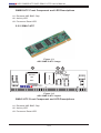
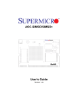
2.2.1 SIMSO-HTC
Figure 1-1
AOC-SIMSO-HTC image
2
3
D10
D9
Heart LED
5
6
Reset LED
1
4
BMC Chip
Renesas
H8S
SIMSO-HTC
Figure 1-2
AOC-SIMSO-HTC layout
2-1
AOC-SIMSO-HTC/AOC-SIMLC-HTC User’s Manual
SIMSO-HTC Front Component and LED Descriptions
#1. Renesas H8S BMC Chip
#2. Activity LED
#3. Processor Reset LED
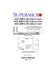
2.2.2 SIMLC-HTC
Figure 1-3
AOC-SIMLC-HTC image
H8S
D10
3
Reset LED
SRAM
Renasas
Activity LED
2
D9
1
BMC
SIMLC-HTC
Figure 1-4
AOC-SIMLC-HTC layout
SIMLC-HTC Front Component and LED Descriptions
#1. Renesas H8S BMC Chip
#2. Activity LED
#3. Processor Reset LED
2-2
Chapter 2: Installation
2-3
LED Descriptions and Pin Definitions
#2. Activity LED Indicator
Activity LED Indicator Table
Activity LED (marked #2 above), located on the card, indicates the functionality and activity of the card. The
blinking of the Activity LED indicates
that the add-on card is active. See
the table on the right for details.
Activity LED
(D1)
On (Blinking)
Card is active
Off
Card is not active
#3. Processor Reset LED
The LED will blink for a fraction of a
second when the BMC card is reset.
You can see this LED flash when you
plug the power cable in.
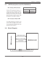
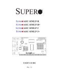
Block Diagram
UART Interface (SOL)
IPMI Connectors
2-4
Supermicro Featured GPIO
LPC Interface
SMDATA
SMCLK
SMALT#
2-3
RENESAS H8S
AOC-SIMSO-HTC/AOC-SIMLC-HTC User’s Manual
2-5
Installation
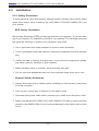
2.5.1 Safety Guidelines
To avoid personal injury and property damage please carefully follow all the safety
steps listed below when installing the AOC-SIMLC-HTC/AOC-SIMSO-HTC into
your system.
ESD Safety Guidelines
Electrostatic Discharge (ESD) can damage electronic components. To prevent damage to your system, it is important to handle it very carefully. The following measures
are generally sufficient to protect your equipment from ESD.
•
•
•
Use a grounded wrist strap designed to prevent static discharge.
Touch a grounded metal object before removing a component from the antistatic
bag.
Handle the add-on card by its edges only; do not touch its components, peripheral chips, memory modules or gold contacts.
•
When handling chips or modules, avoid touching their pins.
•
Put the card and peripherals back into their antistatic bags when not in use.
General Safety Guidelines
•
Always disconnect power cables before installing or removing any components
from the computer.
•
Use only the correct type of bracket for the add-on card.
•
Disconnect the power cable before removing any cable from the add-on card.
•
Make sure that the AOC-SIMLC-HTC/AOC-SIMSO-HTC add-on card is securely
seated in the SIMSO/ SIMLC slot to prevent damage to the system due to short
circuit.
2-4
Chapter 3: Troubleshooting
Chapter 3
Software Application and Usage
With an independent I/O processor embedded in Hitachi’s Renesas H8S System
Chip, the AOC-SIMSO-HTC and AOC-SIMLC-HTC Add-On Cards allows the user
to access, monitor, manage and interface with systems that are in remote locations
via LAN. The necessary utilities for the access and configuration of the add-on
card are included on the Supermicro bootable CDs that came with your card. This
section provides information on the configuration and the access of the IPMI card
on the network.
Contents of the CD
•
•
Firmware: Utility and firmware image used to update BMC Firmware. It can only
be executed under DOS.
J2RE1_5_0: Java Runtime Environment for both Windows and Linux. Users
can also download the latest version from Sun Microsystems, Inc. http://java.
sun.com/
•
DiskImage: Images for storing updates on floppy diskettes.
•
Res: Used by the CD Auto-run feature.
•
IPMI Solution:
•
Linux: IPMIView and Power Control Agent for Linux.
•
Utility: BMC utilities.
•
Windows: IPMIView and Power Control Agent for Windows.
•
Jar: This folder includes IPMIView and TrapReceiver jar files
•
Manual: SIMHTC.pdf: The file you are now looking at.
•
Intel: LAN driver for onboard network adapter.
3-1
AOC-SIMSO-HTC/AOC-SIMLC-HTC User’s Manual
3-1
BMC Firmware Update
1. Shut down the system and unplug the AC power cord.
2. Insert the BMC card.
3. A: If you use a supplied CD-ROM, follow the steps below:
•
•
Turn on your computer and put the IPMI CD into the CD-ROM drive.
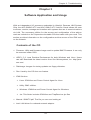
You will see the following prompt. You can choose option 1 to automatically
detect the model number of the motherboard and flash the IPMI card or choose
2 if you know the model number of your motherboard.
Step 1. If you choose option 1 (Automatic detection) you will see the following
screen.
3-2
Chapter 3: Troubleshooting
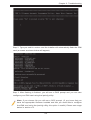
Step 2. Type yes and hit <enter> and the installer will automatically flash the IPMI
card (a screen as shown below will appear).
Step 3. After flashing is finished, you will see a DOS prompt and you can also
configure your IPMI card using the ipmicfg utility.
Note: If you choose No you will see a DOS prompt. (If you know that you
have the appropriate firmware installed and that you would like to configure
the IPMI card using the ipmicfg utility, this option is useful.) Please see usage
below in section 4.3.
3-3
AOC-SIMSO-HTC/AOC-SIMLC-HTC User’s Manual
Step 4. If you choose to manually flash the firmware, you will see the following
screen appear. After flashing the firmware you will see a DOS prompt. On this
prompt you can configure your IPMI card using the ipmicfg utility. Please see usage
below in section 4.1.
Step 5. If you choose to manually flash the firmware, you will see the following
screen appear. After flashing the firmware you will see a DOS prompt. On this
prompt you can configure your IPMI card using the ipmicfg utility. Please see usage
below in section 4.1.
3-4
Chapter 3: Troubleshooting
3. B: If you wish to use a floppy to flash your IPMI card, please complete the
following steps:
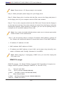
Step 1. Place the CD in your computer (Windows should have been installed). If
you have autorun enabled, you will see the following screen (see below). Otherwise
double click on the CD-ROM icon in your ‘My computer’ window, and it will bring
up the screen below.
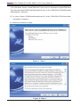
Step 2. Click on ‘Make BMC Firmware Upgrade Diskette’.
Step 3. Follow the instructions on the next screen and choose your motherboard
from the list provided.
3-5
AOC-SIMSO-HTC/AOC-SIMLC-HTC User’s Manual
Note: Please have a 3.5 floppy ready to be inserted.
Step 4. When prompted, place floppy into your floppy drive.
Step 5. When floppy drive is written with the files, remove the floppy and place it
in the floppy drive of your computer with the IPMI card installed.
Step 6. Turn on the computer which has the IPMI card. Ensure that the floppy is
on the top in boot priority. Once the computer is booted from the floppy, it will start
flashing the firmware. When flashing is complete, you can use the ipmicfg utility to
configure the IP and MAC address of the card.
Note: If you make a bootable diskette please make sure to choose appropriate
model number of the motherboard.
Step 7. Use the ipmicfg utility to configure IP address, MAC address, gateway IP
etc. Please use instructions below to choose the correct IP and MAC address.
•
IP address: IP address of LAN1
•
MAC address: MAC address of LAN1.
•
IP address and MAC address of your LAN1 can be seen using ‘ipconfig’ command in Windows and ‘ifconfig’ command in Linux/BSD.
Note: When plugging or unplugging a BMC card, you must first unplug the
AC power cord.
IPMICFG usage:
IPMICFG Version 1.06 (Build 070824) Copyright 2007 SuperMicro Computer Inc.
Usage: IPMICFG params (Example: IPMICFG -m 192.168.1.123)
-m
Show IP and MAC
-m IP
Set IP (format: ###.###.###.###)
-a MAC
Set MAC (format: ##:##:##:##:##:##)
-k
Show Subnet Mask
-k Mask Set Subnet Mask (format: ###.###.###.###)
-dhcp on Enable the DHCP
3-6
Chapter 3: Troubleshooting
-dhcp off Disable the DHCP
-g
Show Gateway IP
-g IP
Set Gateway IP (format: ###.###.###.###)
-r
BMC cold reset
-garp on Enable the Gratuitous ARP
-garp off Disable the Gratuitous ARP
3-2
Overview of IPMI View
IPMI View is management software based on IPMI specification version 1.5 - 2.0.
IPMI View sends IPMI messages to and from the BMC (Base Management Card) on
a remotely managed system. IPMI messages are encapsulated in RMCP (Remote
Management Control Protocol) packets called “datagrams”. This method is also
referred to as “IPMI over LAN”.
The Distributed Management Task Force (DMTF) has defined RMCP for supporting
pre-OS and OS-absent management. RMCP is a simple request-response protocol
that can be delivered using UDP (User Datagram Protocol) datagrams. IPMI-overLAN uses version 1 of the RMCP protocol and packet format. An RMCP packet
is transmitted via IP (Internet Protocol) networking. Thus, system managers may
manage their IPMI-enabled system over the Internet. (Of course, in a private LAN
this is a basic feature.) IPMI uses the same UDP port number (623 in decimal)
with ASF (Alert Standard Forum) protocol. If the managed system is protected by
a firewall, UDP port 623 must be opened.
In Supermicro’s IPMI solution, a BMC shares the LAN1 NIC on the mainboard. The
NIC will re-route the IPMI packet to the BMC instead of forwarding it to the upper
layer network protocol stacks (as other protocol packets do).
IPMI View V2.0 covers Supermicro’s BMCs for both IPMI v1.5 and IPMI v2.0.
However, according to design changes, some functions added to IPMI v2.0 are
not available in IPMI v1.5, and some functions are no longer available in IPMI v2.0
implementation. IPMI View will automatically hide any function that is not available
to the BMC version being used.
3-3
Software Installation Procedures
1. On the system you will manage from:
a) Installing the IPMIView:
3-7
AOC-SIMSO-HTC/AOC-SIMLC-HTC User’s Manual
i) For Windows: Select “Install IPMIView” from auto-run windows to install IPMIView.
You may also select IPMIView20setupwin32.exe” in the “IPMI SOLUTION/Windows/
Administrator” directory.
ii) For Linux: Select “IPMIView20setuplinux.bin” in the “IPMI SOLUTION/Linux/Administrator” directory.
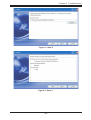
iii) IPMIView installation steps:
Figure 1: Step 1
Figure 2: Step 2
3-8
Chapter 3: Troubleshooting
Figure 3: Step 3
Figure 4: Step 4
3-9
AOC-SIMSO-HTC/AOC-SIMLC-HTC User’s Manual
Figure 5: Step 5
Figure 6: Step 6
3-10
Chapter 3: Troubleshooting
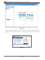
3-4
System Management
The following screen shows the main functions of the IPMI View screen. From this
screen, the user can manage the features of the IPMI View software.
Figure 2-1
Note: This screen is only a model of the System Management.
As shown in Figure 2-1, there are several components in the IPMI View window
(Figure 2-2):
•
•
•
•
•
•
•
Menu Bar: Contains functions allowing you to add/delete systems or groups
and save configurations.
System List: Lists the computers managed with a BMC card.
Group List: Lists managed computer groups for more convenient management.
Viewing Window: shows detailed information including Login, IPMI Device, Event
Log, Sensors, BMC Setting and Text Console.
Status Area: Shows messages regarding current status.
System View Sessions: IPMI View may manage up to 20 systems at the same
time. The current managed system is indicated in the System View window.
Logo: Press Logo to visit Supermicro’s web site.
3-11
AOC-SIMSO-HTC/AOC-SIMLC-HTC User’s Manual
Figure 2-2
Step 1. As shown in Figure 2-3, click “File>New…>System” to add a new system
to IPMI View. An “Add a new system…” dialog box will pop up as shown in Figure
2-4.
Figure 2-3
3-12
Chapter 3: Troubleshooting
Figure 2-4
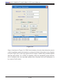
Step 2. As shown in Figure 2-4, in the “Add a new system” dialog box, type in the
desired System Name for the managed system and the correct IP address, as well
as a description. Then click OK.
Figure 2-5
Step 3. As shown in Figure 2-5, To maintain systems easier, the manager may
categorize managed systems into different groups. A system may be included in
multiple groups. The default group is IPMI Domain. All managed systems belong
to IPMI Domain even if they join other groups.
In Figure 2-3, click menu “File>New…>Group” to add a new group to IPMI View.
An “Add a new group” dialog will pop up as shown in Figure 2-5. In the “Add a
new group” dialog box, type in the desired Group Name and description. Then
click OK.
3-13
AOC-SIMSO-HTC/AOC-SIMLC-HTC User’s Manual
Figure 2-6
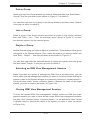
Step 4. As shown in Figure 2-6, IPMI View includes a function that allows the user to
collect candidate system information in order to build their information into a System
List (see Figure 2-6). User may specify the IP range to search any possible system
that has either IPMI 1.5 or IPMI 2.0 capability. After the candidate system information is collected, the user may add systems into a System List by IP addresses, or
by a given Prefix name.
3-14
Chapter 3: Troubleshooting
Figure 2-7
Step 5. As shown in Figure 2-7,
Reload Configuration
From the pull-down menu, click “File>Reload Configuration” to load the previous
saved configuration.
Save Configuration
From the pull-down menu, click “File>Save Configuration” to save the current IPMI
View configuration.
To exit IPMI View from the pull-down menu, click “File>Exit” or press Alt-F4 when
the IPMI View is running.
Note: Remember to save your configuration before exiting.
3-15
AOC-SIMSO-HTC/AOC-SIMLC-HTC User’s Manual
Figure 2-8
Step 6. As shown in Figure 2-8,
Modify System
Select a system in the System Window you want to modify and then click
“Edit>Modify…>System” from the pull-down menu shown in Figure 2-7 to modify
it.
You can also right click on a system in the System Window, and then select “Modify”
in the pop-up menu to modify it.
Delete System
Select a system in the System Window you want to delete, and then click
“Edit>Delete…>System” from the pull-down menu shown in Figure 2-7 to delete
it.
You can also right click on a system in the System Window, and then select “Delete”
in the pop-up menu to delete it.
Modify Group
Select a group in the Group Window you want to modify and then click “Edit>Modify…
>Group” from the pull-down menu shown in Figure 2-7 to modify it.
You can also right click on a group in the Group Window, and then select ”Modify”
in the pop-up menu to modify it.
3-16
Chapter 3: Troubleshooting
Delete Group
Select a group in the Group Window you want to delete and then click “Edit>Delete…
>Group” from the pull-down menu shown in Figure 2-7 to delete it.
You can also right click on a group in the Group Window, and then select ”Delete”
in the pop-up menu to delete it.
Join a Group
Select a group in the Group window and select a system in the System Window,
then click “Edit>…Join…” from the pull-down menu shown in Figure 2-7 to have
the selected system join the desired group.
Disjoin a Group
Double click the group you want to disjoin a system from. The members of that group
will appear in the System Window. Then, select the system you want to disjoin and
click “Edit>…Disjoin…” from the pull-down menu shown in Figure 2-7.
You can also right click the selected system to disjoin the system from the group
and then select “Disjoin” in the pop-up menu to delete it.
Selecting an IPMI View Management Session
When more than one system is managed by IPMI View at the same time, you can
select which opened management session you want to control by double clicking on
system’s name in the System Window or by selecting “Session><<System name>>”
in the pull-down menu, where <<System name>> denotes the name of the target
system you want to control (as shown in Figure 2-8).
Closing IPMI View Management Session
To close the opened IPMI View management session, select the IPMI View management session you want to close as the current IPMI View management session
and then click “Session>Close <<System name>>” in the pull-down menu, where
<<System name>> denotes the name of the system you want to close (as shown
in Figure 2-8).
3-17
AOC-SIMSO-HTC/AOC-SIMLC-HTC User’s Manual
Or - right click on the system in the System Window you want to close and select
“Close Session” in the pop-up menu to close it.
When closing a session, a session will not be closed until 1) replies have been
received for all outstanding packets or 2) all outstanding packets have timed out.
3-5
Login
In Figure 3-1, double click the system in the System Window you want to manage.
A login screen along with some information about the managed system will appear
in the Viewing Window. Type in the login ID and password and click the Login button to log in. When a login is successful, the Login button is grayed (i.e. disabled)
and the Logout button is enabled as well as the availability of other management
functions, as shown in Figure 3-0.
Figure 2-9
3-18
Chapter 3: Troubleshooting
Figure 3-0
Note: The default Login ID is “ADMIN”,,which has the default password of
“ADMIN”. Both the Login ID and Password are case-sensitive.
In the IPMI design, an MD5 algorithm will encrypt the password when it is transmitted through the network. Once the password is confirmed, IPMI View will show a
CONNECTED symbol, and all available function pages will be shown as seen in
Figure 3-0. If the password is invalid, it will show a message in the Status Area
that reads “Unable to activate a session, please check ID and Password” and a
Break symbol will be shown (see Figure 2-9).
3-19
AOC-SIMSO-HTC/AOC-SIMLC-HTC User’s Manual
Figure 3-1
Note: In order to reduce overhead on the managed system, all pages will not
refresh automatically. The user must refresh manually as needed.
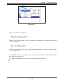
3-6
IPM Device
Figure 3-2
3-20
Chapter 3: Troubleshooting
Clicking the IPM Device tab of the IPMI View management session in the
Viewing Window (shown in Figure 3-2) will display some information and
functions of the system’s BMC firmware.
Device Information
This shows the revision levels of the BMC and IPMI firmware.
ACPI System Power State
This shows the managed system’s power state. If the managed system
is in a power-off state, the green light will be off. This status will update
automatically every five seconds.
Graceful Power Control (Administrator and
Operator only)
Graceful power control will inform the OS running on the managed system
to shutdown/reboot/power-cycle within a specified time (the default is
30 seconds). When the OS running on the managed system receives a
graceful power control request, it will generate a pop-up window on the
managed system’s monitor and start a count down. This pop-up notice
window gives the user who is working on the system a chance to save any
working files. However, remote login users or service users (for example
Web site visitors) will not see this notice.
Graceful Shutdown
Same as the shutdown function in Windows. The managed system will
enter an S5 state.
Graceful Reboot
Same as the reboot function in Windows.
Graceful Power Cycle
This function is a combination of the Graceful Shutdown and Power Up
functions.
3-21
AOC-SIMSO-HTC/AOC-SIMLC-HTC User’s Manual
The Power Cycle function will shut down the managed system for a few seconds
and then power up the system. Graceful power control will send an event to the
System Event Log (next section). If no more memory space is left for the incoming
event, graceful power control will not function.
Chassis Power Control (Administrator and Operator only)
This function is used to forcibly control the power state of the managed system’s
chassis. When the BMC receives a chassis power control command, it will have
direct control over the power button or reset button of a system.
Reset
This is the same as pressing the Reset button on a managed system’s chassis to
reset the managed system.
Power Down
This is the same as pressing the Power button on a managed system’s chassis to
remove power from the managed system.
Power Up
This is the same as pressing the Power button on a managed system’s chassis to
turn on the power of the managed system.
Power Cycle
This function is a combination of the Power Down and Power Up functions.
The Power Cycle function will shutdown the managed system for a few seconds
and then power up the system.
BMC Cold Reset (Administrator only)
Clicking the Cold Reset button allows you to reset the BMC. After confirming to reset
the BMC, the session will break immediately. The user has to close this session
manually. This function is rarely used, only in events such as when a malfunction
is suspected.
3-22
Chapter 3: Troubleshooting
3-7
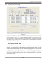
System Event Log
Figure 3-3
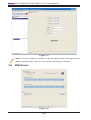
Clicking on the Event Log tab of the IPMI View management session in the Viewing
Window (shown in Figure 3-3) gives you detailed information on the System Event
Log for the BMC. It shows the System Event Log version, number of log entries,
free space for the System Event Log and the times of recently added and recently
erased System Event Logs.
Get System Event Log
In the Get Entries group on the upper left side of the Event Log tab in the Viewing
Window, you can decide how many logs you want to get from the BMC. Click the
<From> button and type in the first and last numbers of the logs you wish to view,
or click the <All> button to get all the logs from the BMC. The logs retrieved from
the BMC will listed as a table in the central part of the Viewing Window. Please
refer to the IPMI specifications version 2.0 for detailed descriptions of each field.
Some helpful fields:
3-23
AOC-SIMSO-HTC/AOC-SIMLC-HTC User’s Manual
Timestamp
The time the event happened.
Sensor Type
This could be health sensors or a system event.
Event Type
The event description.
Because the BMC communicates with the NIC on the mainboard via a slow channel,
requesting only the events you need to see is recommended. Choosing “all” to get
hundreds of event entries will result in a very long delay.
Clear System Event Log
Clicking the Clear All Entries button clears the logged system events on the BMC.
The total event log space is 16 KB. When all this space is used, any incoming event
will be lost. The user has to clear the system event log manually as needed.
Time Stamp of System Event Log and Time Zone
To set the time stamp of the BMC on the managed system, type in the time in
the Current SEL Device Timestamp field. Then click the Set Timestamp button to
update the BMC.
3-24
Chapter 3: Troubleshooting
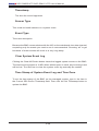
3-8
Sensors
Figure 3-4
Clicking on the Sensors tab of the IPMI View management session in the Viewing
Window (as shown in Figure 3-4) provides you with detailed information on the
sensors monitored by the BMC. It shows the reading of supported voltages and fan
speeds and temperatures monitored by the BMC. The current reading is shown in
yellow numbers, the high limits/low limits in red numbers and a description for the
monitoring sensors in blue text beneath the monitoring sensor figures.
Fan speeds have only a low limit, temperatures have only a high limit, and voltages
have both high and low limits.
Refreshing Monitor Status
You can configure the IPMI View to automatically refresh the monitoring status periodically by checking the Auto Refresh check box and selecting the refresh period
in seconds in the seconds list. Or, click the Manual Refresh button to refresh the
monitoring status every time you need an update.
3-25
AOC-SIMSO-HTC/AOC-SIMLC-HTC User’s Manual
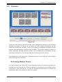
Hide Inactive Item
IPMI View gets predefined sensor information from the mainboard. Some items may
be not installed for different configurations. For example, there will be no CPU fan if
using a passive CPU heat sink, and only one CPU on a dual CPU mainboard that
has only a single CPU installed. The first time the sensors page is shown, IPMI View
will hide inactive items (the default setting) if any. A manager may change this option
later by un-checking the “Hide inactive item” box, as shown in Figure 3-5.
Figure 3-5
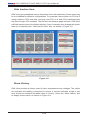
Show History
IPMI View provides a history chart for fans, temperatures and voltages. The yellow
line indicates the reading correspond to sensor. A red line indicates a high or low
limit. A blue line indicates the base value of 0 (zero). Check the “Show History” box
to display these charts, as shown in Figure 3-6.
3-26
Chapter 3: Troubleshooting
Figure 3-6
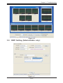
3-9
BMC Setting (Administrator only)
Figure 3-7
3-27
AOC-SIMSO-HTC/AOC-SIMLC-HTC User’s Manual
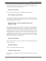
Clicking on the BMC Setting tab of the IPMI View management session in the
Viewing Window (as shown in Figure 3-7) gives you detailed information on the
BMC LAN Configuration, SNMP trap configuration and serial communication port
of the BMC.
In order to support the power-down state management capability under the IPMI
specification, the manager has to configure the proper MAC address for each IP address. To deliver an IP packet to a receiver, the sender needs to know the receiver’s
MAC address or the gateway’s MAC address. ARP (Address Resolution Protocol)
is used to get the MAC address from the IP address. While the managed system’s
OS is running, the network protocol stack will take care of this function. However,
when the managed system is in a power down state, this function cannot be accomplished. Therefore, each MAC address has to be configured manually.
The BMC and the OS running on a managed system may use different IP addresses
for security reasons. For example, the OS may use 66.201.4.73 (which can be
reached by public access) while the address for BMC may be set to 192.168.1.55,
which can only be reached in a private LAN. But, LAN MAC addresses must be
the exact same. If the BMC uses a private IP address, you have to make sure that
the manager’s system can communicate with the private IP address for the BMC
on a managed system.
BMC LAN Configuration
This shows the IP address, LAN MAC, Gateway IP, Gateway MAC and Subnet
Mask of the BMC and allows you to modify them.
Note: Please make sure that the MAC address of the LAN and the gateway for
the BMC are correct before updating it by clicking the Update button. Be careful
to enter the correct values, especially for the LAN MAC. If you enter the wrong
LAN MAC, IPMI View will not be able to connect to that system any more.
If you accidentally enter a wrong LAN MAC value, you may use the ipmicfg instructions from the BMC firmware update (See section 4, page 13).
SNMP
This shows the SNMP trap configuration of the system needing to receive the
SNMP traps generated by the BMC and allows you to modify them. To change the
configuration on the BMC, type in the SNMP community name in the Community
3-28
Chapter 3: Troubleshooting
text field and the IP address and MAC address in the SNMP Trap Receivers table
in the SNMP group, and then click the Update button.
The SNMP Trap may have multiple destinations. When any critical error occurs, an
SNMP trap packet will be sent to all receivers in the list. To remove an SNMP receiver, you may change both IP and MAC addresses to 0.0.0.0 and 00:00:00:00:00:00
respectively, and then click Update.
On the system receiving the SNMP traps, an SNMP trap receiver software needs
to be installed and run. The managed system will send out an SNMP trap packet to
receivers at the moment the event occurs. If an SNMP trap receiver is not running,
the trap packet is discarded and won’t be queued anywhere.
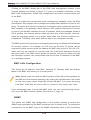
3-10 Users
There are several buttons that allow you to add/delete a user, set user privileges,
change passwords and enable/disable paging.
Group Privilege Levels
Callback
This may be considered the lowest privilege
level. Only commands necessary to support
initiating a Callback is allowed. (Only available for IPMI 1.5.)
User
Only ‘benign’ commands are allowed. These
are primarily commands that read data
structures and retrieve status. Commands
that can be used to alter BMC configuration,
write data to the BMC or other management
controllers or perform system actions such
as resets, power on/off, and watchdog activation are not allowed.
Operator
All BMC commands are allowed, except for
configuration commands that can change
the behavior of the out-of-band interfaces.
For example, Operator privilege does not
allow the capability to disable individual
channels or change user access privileges.
Administrator
All BMC commands are allowed, including
configuration commands. An Administrator
can even execute configuration commands
that would disable the channel that the Administrator is communicating over
Clicking on Paging Setting allows you to set the parameters for an individual user
(Figure 3-8). There are two types of paging service: Numeric paging and alphanumeric paging. To use a paging service, a modem must be connected to the RS232
connector on the BMC.
3-29
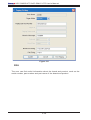
AOC-SIMSO-HTC/AOC-SIMLC-HTC User’s Manual
Figure 3-8
FRU
The user can find useful information about the board and product, such as the
serial number, part number and part name of the board and product.
3-30
Chapter 3: Troubleshooting
3-11 Text Console Redirection (SOL, Serial Over LAN)
Figure 3-9
On the Text Console tab of the IPMI View management session in the Viewing
Window (as shown in Figure 3-9), there is a function for you to remotely control
the managed system in a text mode console. Click the Start button to start the text
console redirection. During control, click the Re-synch button to synchronize the
text console with the managed system if you think the screen is not shown properly.
Click the Stop button to stop the text console.
SOL for IPMI 2.0
IPMI specification V2.0 defines Serial over LAN (SOL) to support Text Console
Redirection. This implementation performs better than the one we implemented for
IPMI 1.5. The Text mode console remains working on Windows 2003, even when
the OS is running. To support Text Console Redirection on Windows 2003, Special
Administration Console (SAC) must be enabled. The following instruction is used
to enable SAC:
3-31
AOC-SIMSO-HTC/AOC-SIMLC-HTC User’s Manual
For Windows 2003:
1. Enable Console Redirection in BIOS, and set it to COM 2 (or COM B)
2. Modify boot.ini in C:\. Boot.ini is a hidden file. Below is an example of boot.ini
[boot loader] redirect=com2 redirectbaudrate=19200 timeout=30 default=multi(0)di
sk(0)rdisk(0)partition(1)\WINDOWS [operating systems] multi(0)disk(0)rdisk(0)parti
tion(1)\WINDOWS=”Windows Server 2003, Standard” / fastdetect /redirect
For Linux:
1. BIOS POST:
(i) Enable “Console Redirection” in BIOS Setup. For example, COM2 /
19.2Kbps / 8N1
(ii) Disable “Enable Console Redirection after POST” in BIOS setup.
2.
BOOT LOADER:
(i) For GRUB, add the following TWO lines into /boot/grub/grub.conf, but
comment out “splashimage=(hd0,0)/grub/splash.xpm.gz”
serial --unit=1 --speed=19200 --word=8 --parity=no --stop=1
terminal --timeout=10 serial console
#splashimage=(hd0,0)/grub/splash.xpm.gz
(ii) Then add “serial console=ttyS1,19200n8” to the end of kernel /vmlinuz in
/boot/grub/grub.conf.
For example:
kernel /vmlinuz-2.6.5-1.358smp ro root=LABEL=/ rhgb quiet serial
console=ttyS1,19200n8
This will result in all boot messages to be output to console ttyS1, and you will
not see all these boot messages at the local console until login message promt
up.
c) Under LINUX OS:
(i) Add the following line into /etc/inittab.
s0:2345:respawn:/sbin/agetty ttyS1 19200
(ii) Edit /etc/securetty and add ttyS1
3-32
Chapter 1: Introduction
Chapter 4
Troubleshooting
4-1
1.
Frequently Asked Questions
Question: How do I configure SIMLC-HTC/SIM1U-HTC/SIMSO-HTC?
Answer: Boot from the supplied CD with your IPMI card. The CD will auto-detect
motherboard type and flash IPMI card. You can use the ipmicfg.exe utility to configure the IP address and MAC address of the IPMI card.
2.
Question: Which IP and MAC address should I use for SIMLC-HTC/
SIMSO-HTC?
Answer: You need to use LAN1 IP and MAC address for your IPMI card when you
program it using ipmicfg.exe utility.
3.
Question: Can I configure Gateway IP address of my IPMI card?
Answer: Yes you can use the ipmicfg.exe utility to configure IPMI card.
4.
Question: Do I need to install any driver on my server, which has an
IPMI card?
Answer: No driver installation is required on your host which has an IPMI card.
4-2
Contacting Supermicro’s Technical Support
If you still have problems after trying out all the recommended solutions, please
contact our technical support @ (408) 503-8000 or visit our web site @ www.
supermicro.com/support/.
4-1
AOC-SIMSO-HTC/AOC-SIMLC-HTC User’s Manual
Notes
4-2