1
X7DBR-3/X7DBR-E User's Manual
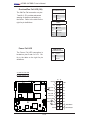
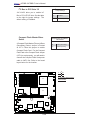
Wake-On-Ring
Wake-On-Ring
Pin Definitions
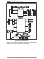
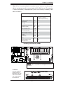
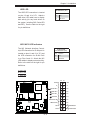
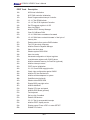
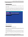
The Wake-On-Ring header is designated JWOR. This function allows
your computer to receive and be
"awakened up" by an incoming call
Pin#
Definition
1
Ground
2
Wake-up
to the modem when the system is in
the suspend state. See the table on
the right for pin definitions. You must
have a Wake-On-Ring card and cable
to use this feature.
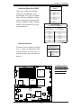
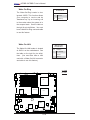
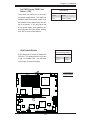
Wake-On-LAN
Wake-On-LAN
Pin Definitions
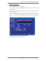
The Wake-On-LAN header is located
at JWOL1 on the motherboard. See
the table on the right for pin definitions. (You must also have a LAN
card with a Wake-On-LAN connector
and cable to use this feature.)
Pin#
Definition
1
+5V Standby
2
Ground
3
Wake-up
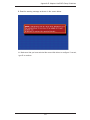
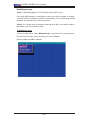
A. WOR
SUPER
20-pin ATX Main PWR
Fan1
DIMM 3A
Fan2
CPU1
FP Ctrl
DIMM 2B
DIMM 2A
DIMM 1B
DIMM 1A
Fan3
North Bridge
PXH-V
JI 2C2
SXB- E3x8
Battery
JWF1
S I/O
JPG1
Act#4-7
SIMSO
JPS1
SMB
IPMB
A
BIOS
JBT1
B
WOL
LE1
Pres#4-7
COM2
SAS
CTRLR
JP11 JP10
SAS 4-7
VGA
CTRLR
Buzzer
JP12
South
Bridge
SGPIO2SGPIO1
JOH1
J7
Pre#0-3
JL1
Act#0-3
SAS 1-3
JPL1
JPL2
VGA
GLAN
CTRLR
Fan5
IDE1
SXB- E2x8
PCI-X 133MHz
JCF1JWD
SXB-E1x8
PCI-X 100MHz ZCR
GLAN2
Compact Flash
JI 2C1
GLAN1
Fan4
CPU2
Floppy
Bank1
COM1
B. WOL
4-pin
8-pin PWR
PWR
JPWF
JAR
DIMM 4A
Bank2
USB0/1
PWR
SMB
PWR
X7DBR-3/E 3rd
Fail
DIMM 3B
Bank3
MS
®
DIMM 4B
Bank4
KB
USB4/5 USB2/3 SATA1 SATA3 SATA5
J8
SATA0 SATA2 SATA4 JS10
WOR PWLED SPK J4E3
2-18