1
5
PM3 and PM4 Series
Modular Surge Protection Device (SPD)
User’s Manual
Copyright © 2000 American Power Conversion Corporation
132 Fairgrounds Road
P.O. Box 278
West Kingston, Rhode Island 02892 USA
990-0524 10/00
6XUJH$UUHVW306HULHV
Contents
INTRODUCTION.......................................................................................................................................... 1
Installation.......................................................................................................................................... 1
Testing ................................................................................................................................................ 1
UNPACKING AND PRELIMINARY INSPECTION................................................................................ 1
Unpacking & Preliminary Inspeciton................................................................................................. 1
Storage................................................................................................................................................ 1
LOCATION CONSIDERATIONS ............................................................................................................... 2
Environment ....................................................................................................................................... 2
Audible Noise..................................................................................................................................... 2
Mounting and Cabinet Data ............................................................................................................... 2
Service Clearance............................................................................................................................... 3
Equipment Performance..................................................................................................................... 3
Product Orientation ............................................................................................................................ 3
System Grounding.............................................................................................................................. 3
ELECTRICAL CONNECTIONS ................................................................................................................ 4
Overcurrent Protection ....................................................................................................................... 4
Voltage Rating .................................................................................................................................... 4
Terminals ............................................................................................................................................ 4
System Gounding ............................................................................................................................... 4
Parallel Connection ............................................................................................................................ 5
Wire Size ............................................................................................................................................ 5
PM SERIES INSTALLATION INSTRUCTIONS...................................................................................... 5
Typical Unit Installation, Three Phase WYE, 4 Wire, plus Ground .................................................. 5
Disconnect Switch Option.................................................................................................................. 8
OPERATION and FEATURES .................................................................................................................... 9
6WDWXV3DQHO&RQWUROV,QGLFDWRUVDQG$ODUPV ................................................................................. 10
Surge Counter Option....................................................................................................................... 10
Dry Contacts Option......................................................................................................................... 10
CORRECTIVE MAINTENANCE (Repair) ............................................................................................. 11
Troubleshooting................................................................................................................................ 11
Display Board Removal and Replacement Instructions................................................................... 13
Diagnostic Board Removal and Replacement Instructions.............................................................. 14
Surge Module Removal and Replacement Instructions ................................................................... 14
PREVENTIVE MAINTENANCE - Inspection and Cleaning ................................................................. 15
REPLACEMENT PARTS LIST................................................................................................................. 16
LIMITED WARRANTY ............................................................................................................................. 17
TECHNICAL SUPPORT ............................................................................................................................ 17
i
Contents - continued
Tables
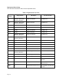
Table 1 - PM3 and PM4 Dimensions and Weights ............................................................................ 2
Table 2 - Voltage Rating and Service Type (by Model) ..................................................................... 4
Table 3 - Relay Contact Pin Arrangement ....................................................................................... 11
Table 4 - Replacement Parts List...................................................................................................... 16
Figures
Figure 1 - Typical Parallel Connections ............................................................................................. 5
Figure 2 - Basic PM3 Configuration and Wiring Diagram ................................................................ 7
Figure 3 - Basic PM4 Configuration with Disconnect Switch Option............................................... 8
Figure 4 - Status Panel with Surge Counter Option ......................................................................... 10
Figure 5 - Troubleshooting Flow Chart............................................................................................ 12
Figure 6 - Display Board Locator Diagram ..................................................................................... 13
Figure 7 - Diagnostic Board Locator Diagram................................................................................. 14
Figure 8 - Surge Module Removal and Replacement ...................................................................... 15
ii
INTRODUCTION
Thank you for choosing the APC SurgeArrest PM3 or PM4 Series Surge Protection Device.
The APC modular Surge Protection Device (SPD) is a high quality, high energy surge attenuation system that has
been designed to protect sensitive equipment from damaging transient voltage surges. Proper installation is imperative to maximize the surge suppressor’s effectiveness and performance.
Read and understand all information contained in this manual prior to installation. This manual is to be used as a
guide for installing the device. The procedures contained in this manual are not intended to supercede local or
national electical codes. Check all applicable electrical codes to assure compliance. In all instances, local and/or
national electric code requirements are to be followed.
This device must be installed by a licensed electrician. The electrician should follow the steps outlined in this manual to insure proper installation. A copy of the installer’s invoice detailing the installation of this device is
required in order to obtain warranty service for the device.
The PM Series modular product line is a parallel SPD designed for service entrance and downstream panelboard
applications.
The PM Series has one module per phase and is available with a 120kA or 160kA per phase rating. All APC products
are extensively tested according to industry standards as set by IEEE C62.41, and C62.45, for Categories A, B, and C.
The connection method of these devices may require several feet of wire. Increased lead length adversely affects
clamping voltages.
Save this manual! It includes instructions for obtaining warranty service and replacement parts.
INSTALLATION
During installation into an electrical system, SPD’s must NOT be energized until the electrical system is completely
installed, inspected, and tested. All conductors must be connected and functional, including the neutral (if required).
The voltage rating of the device and system must always be verified before energizing the SPD.
Failure to follow these guidelines can lead to abnormally high voltage being applied to the SPD. This may cause the
SPD to prematurely fail or significantly shorten the effective life. The warranty does not cover an incorrectly installed
device.
TESTING
Any factory or on-site testing that exceeds the normal operating voltage such as high-potential insulation testing, or
any other tests where the suppression components will be subjected to voltages higher than their rated "turn on" voltage must be run with the suppressor disconnected from the power source. For 4-wire TVSS devices, the neutral connection at the TVSS must also be disconnected prior to performing high-potential testing and then reconnected upon
completion of the test.
Failure to disconnect this surge suppression device and its associated suppression components during elevated voltage testing will result in damage to the suppression components and/or other electronic components.
Unpacking & Preliminary Inspection
,QVSHFWWKHHQWLUHVKLSSLQJFRQWDLQHUIRUGDPDJHRUVLJQVRIPLVKDQGOLQJEHIRUHXQSDFNLQJWKHXQLW
5HPRYHWKHFDUGERDUGSDFNLQJDQGIXUWKHULQVSHFWWKHXQLWIRUDQ\REYLRXVVKLSSLQJGDPDJHV
,IGDPDJHIRXQGLVDUHVXOWRIVKLSSLQJRUKDQGOLQJLPPHGLDWHO\ILOHDFODLPZLWKWKHVKLSSLQJFRPSDQ\DQG
IRUZDUGDFRS\WR$3&
Storage
The unit should be stored in a clean, dry environment. Storage temperature is -40o C (-40o F) to +60o C (+140o F).
Avoid exposing the unit to areas of high condensation. All of the packaging materials should be left intact until the
unit is ready for installation. If the unit has been stored for an extended period of time, it may be necessary to clean
the unit and make a complete inspection of the unit prior to installing and placing it into service.
Page 1
LOCATION CONSIDERATIONS
7KHIROORZLQJSDUDJUDSKVSURYLGHLQIRUPDWLRQDQGJXLGDQFHDERXWZKDWVKRXOGEHWDNHQLQWRFRQVLGHUDWLRQEHIRUH
LQVWDOOLQJDQ$3&63'
Environment
The unit is designed to operate indoors in an ambient temperature* range of -40o C (-40o F) to +60o C (+140o F) with
a relative humidity of 0% to 95% non-condensing. The standard unit is in a Type 1 industrial use enclosure intended
for indoor use. Primarily, it provides a degree of protection against contact with the enclosed equipment. It should
not be installed in areas with excessive dust, flammable materials, corrosive vapors or explosive atmospheres.
*Surge Counter option has an operating temperature range of -0o C (32o F) to +60o C (+140o F).
Audible Noise
The unit background noise is negligible, and does not restrict the location of the installation.
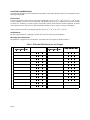
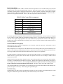
Mounting and Cabinet Data
The PM Series is designed to be wall mounted. Unit model sizes and weights are defined in Table 1.
7DEOH30DQG30'LPHQVLRQVDQG:HLJKWV
:[+['
:HLJKW6KLSSLQJ:HLJKW
[[FP
U
H
E
P
X
1
O
H
G
R
0
Page 2
:[+['
[[FP
:HLJKW6KLSSLQJ:HLJKW
303
OEVNJ
303'
OEVNJ
303
OEVNJ
303'
OEVNJ
30)
OEVNJ
30)'
OEVNJ
30)
OEVNJ
30)'
OEVNJ
30/
OEVNJ
30*'
OEVNJ
30*
OEVNJ
30*'
OEVNJ
30*
OEVNJ
30/'
OEVNJ
30/
OEVNJ
30/'
OEVNJ
30/6
OEVNJ
30/'6
OEVNJ
30*6
OEVNJ
30*'6
OEVNJ
30/6
OEVNJ
30)6
OEVNJ
Service Clearance
In addition to national and local code requirements, 32 inches of service clearance is needed at the front of the SPD.
**Surge Protection Devices are designed for use on the load side
of the service entrance disconnect only**
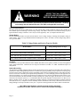
:$51,1*
0$,17(1$1&(2)7+,6685*(3527(&7,21'(9,&(6+28/'%(3(5)250('%<
48$/,),('3(56211(/21/<
'85,1*1250$/23(5$7,21+$=$5'28692/7$*(6$5(35(6(17,16,'(7+(81,7
:+(16(59,&,1*7+,681,7%(685(72)2//2:$//(/(&75,&$/6$)(7<35(&$8
7,216
$//32:(56285&(6727+,681,76+28/'%(/2&.('2))%()25(6(59,&,1*
7+,6:,//35(9(177+(5,6.2)5(&(,9,1*$1(/(&75,&$/6+2&.
Equipment Performance
To obtain the maximum system performance, the unit must be located as close to the circuit to be protected as possible, minimizing the interconnecting wire length. For every foot of wire length, approximately one (1) nanosecond of
turn-on/turn-off time will be added, and approximately 175 volts (6kV/3kA, 8/20 microseconds) will be added to the
clamp voltage.
For optimum transient surge protection, staged surge suppression should be implemented at the service entrance and
all other electrical connections to the building (telephone, CATV, etc.). It should also be implemented at recognized
surge generating loads within the building (arc welding rigs, large motors, switched capacitors, etc.). Additionally, it
should be implemented for sensitive electronic loads (computer equipment, facsimile machines, copy machines, solid
state motor drives, variable frequency drives, etc.). For interconnected electronic loads (via data cabling), surge protection devices should also be utilized to protect the devices on either end of the interconnecting data cables.
APC manufactures a complete line of surge protection devices for both alternating current (AC) and direct current
(DC) applications. Contact an authorized APC reseller, or order directly from APC at www.APC.com.
Product Orientation
To decode the Model Number and determine the unit’s configuration, locate the printed nameplate on the inside of the
unit door. Note: The Serial Number, Date of Manufacture, and UL 1449 Suppression Voltage Rating (SVR) are also
on the unit identification nameplate. The Model Number can be decoded as follows:
30LGHQWLILHVD6XUJH$UUHVW3DQHO0RXQW7KHIROORZLQJDOSKDFKDUDFWHULQGLFDWHVWKHYROWDJHDQGZLULQJ
FRQILJXUDWLRQRIWKHGHYLFH
)ROORZLQJWKHDOSKDFKDUDFWHULVWKHQXPEHURU7KHVHQXPEHUVLGHQWLI\6XUJH&XUUHQW5DWLQJVRIN$
RUN$SHUSKDVHUHVSHFWLYHO\
)ROORZLQJWKHOHWWHUGHVLJQDWLRQLVRSWLRQDOHTXLSPHQWVKRZQDV' 'LVFRQQHFW6 6XUJH&RXQWHU
2SWLRQVDUHGHWDLOHGODWHULQWKLVPDQXDO
Page 3
:$51,1*
9(5,)<7+$7$//32:(5
&,5&8,76$5('((1(5*,=('
%()25(0$.,1*&211(&7,216
All electrical connections should be performed by a qualified (licensed) electrician. All wiring
must comply with the National Electric Code (NEC) and applicable local codes.
Overcurrent Protection
The Surge Protection Device (SPD) draws very little current under normal conditions and will only conduct for a
brief duration upon encountering a transient surge voltage. APC SPD’s contain UL Listed internal fusing to protect
against abnormal voltage conditions. Note: Only use fuses supplied by APC (see Replacement Parts list).
Voltage Rating
Prior to mounting the SPD, verify that the unit has the correct voltage rating by checking the nameplate voltage or
model number. The service type should match the intended power source. See Table 2 for the voltage rating and service type of the SPD.
7DEOH9ROWDJH5DWLQJDQG6HUYLFH7\SHE\0RGHO
0RGHO1XPEHU
9ROWDJH5DWLQJDQG6HUYLFH7\SH
303303'303DQG303'
9ROWV6LQJOH3KDVH
30)30)'30)630)DQG30)'
9ROWV3KDVH:<(:LUH
30*30*'30*30*'30*6DQG30*'6
9ROWV3KDVH:<(:LUH
30/30/'30/630/30/'30/6DQG30/'6
9ROWV3KDVH:<(:LUH
Terminals
Terminals have been provided inside the APC modular SPD units for line (phase), neutral (if used), and equipment
safety ground connections. Terminal wire size range for all models is #8 AWG - #1 AWG. Installation torque is 65
inch-pounds.
System Grounding
An equipment grounding conductor must be used on all electrical circuits connected to the SPD. This requirement is
primarily for safety, although SPD performance is enhanced by proper grounding. Proper operation of any surge suppression system or device depends on a proper grounding system. Incorrect grounding practices will reduce the effectiveness or interfere with SPD system operation and performance, as well as endanger personnel and equipment. For
the best performance, use a single point ground system where the service entrance grounding electrode system is connected to and bonded to all other available electrodes, building steel, metal water pipes, driven rods, etc. For sensitive
electronics and computer systems, it is recommended that the ground impedance measurement be 25 ohms or less.
When a metallic raceway is used as an additional grounding conductor, an insulated grounding conductor should be
run inside the raceway. Adequate electrical continuity must be maintained at all raceway connections. Do not use isolating bushings to interrupt a metallic raceway run. A separate isolated ground for the SPD is NOT recommended.
**On 4-Wire Power Systems, neutral to ground bonding should be
installed per the NEC. Failure to do so could cause equipment damage.**
Page 4
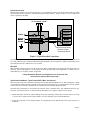
Parallel Connection
When making a parallel type of connection (Figure 1), the length of the wiring to the Surge Protection Device (SPD)
must be kept as short as possible to substantially enhance the performance. Long wire runs are to be avoided if the
unit is to perform as intended.
7R3URWHFWHG/RDGV
3KDVH$
3KDVH%
3KDVHV
1HXWUDO
3KDVH&
1HXWUDO%XV
1HXWUDO
LIXVHG
LIXVHG
*URXQG
*URXQG
*URXQG%XV
Interconnecting Wiring
* Minimize Length
* Avoid Sharp Bends
)LJXUH7\SLFDO3DUDOOHO&RQQHFWLRQV
To reduce the impedance the wire displays to surge currents, the phase, neutral (if used), and ground conductors are to
be routed within the same conduit and should be tightly bundled or twisted together to optimize performance of the
unit. Sharp bends in the conductors are to be avoided.
Wire Size
With a parallel connection, the size of the wiring to the SPD is independent of the ampere rating of the circuit to be
protected. The recommended wire size is based on the unit’s transient surge current capabilities. #6 AWG is the recommended wire size for phase, neutral, and ground.
**Surge Protection Devices are designed for use on the load side
of the service entrance disconnect only**
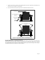
Typical Unit Installation - Three Phase WYE, 4 Wire, plus Ground
This section provides basic installation instructions for the PM3 and PM4 SPDs. Per UL 1449 Paragraph 1.4, SPDs
"are intended for installation on the load side of the main overcurrent protection". Locate the SPD as close as possible
to the circuit to be protected to minimize the wire length. This will optimize SPD performance.
Note that these instructions are not intended to supercede local or national codes. The installation should be performed by a licensed electrician. To install a PM3 or PM4 SPD, refer to Figure 2 and proceed as follows:
1. Unpack and inspect the unit for signs of damage. If the unit is damaged, contact APC Customer Service (see Page
17 for the APC Customer Service phone number, as well as obtaining service under the Warranty.
2. Locate where the unit is to be installed. Ensure wire lengths between the SPD and the service panel are kept to a
minimum.
Page 5
3. Open the door on the unit by loosening the two screws that secure the door latches in place. Slide the top latch
upward and rotate it so that it no longer secures the door. Slide the bottom latch downward and rotate it so that it
no longer secures the door.
4. Drill a hole large enough to allow for the installation of the correct sized UL approved conduit with anti-short
bushings (not supplied) to accomodate the wiring being installed. NOTE: In order to keep wiring length and bend
radii at a minimum, APC recommends that wiring be installed through the left side or bottom of the SPD. APC
also recommends that the hole be sealed with putty after wiring installation.
5. Drill four (4) pilot holes (mounting holes in the SPD are 5/16" in diameter) to provide for mounting of the SPD.
6. Mount the device via the flanges as close as possible to the panel being protected.
:$51,1*
9(5,)<7+$7$//32:(5
&,5&8,76$5('((1(5*,=('
%()25(0$.,1*&211(&7,216
All electrical connections should be performed by a qualified (licensed) electrician. All wiring
must comply with the National Electric Code (NEC) and applicable local codes.
7. Connect the unit to the service panel through the UL approved conduit with anti-short bushings. The connecting
wires should be twisted together or tightly bundled and kept as short as possible to enhance the performance of the
SPD. Terminal wire size range is #8 AWG to #1 AWG. Torque screws to 65 inch-pounds. The recommended wire
size for phase, neutral, and ground is #6 AWG.
Connect a wire (in conduit) to the safety ground bus of the distribution panel, and to the ground connection of the
SPD as shown in the diagram on the following page, and as marked on the unit. Proper grounding is essential, use
a green wire or yellow/green striped wire for the ground connection. Connect a wire (in conduit) to the NEUTRAL
bus of the panel and to the NEUTRAL connector of the SPD as marked on the unit. Use a white wire or mark with
a white band for the neutral connection.
Connect a wire (in conduit) to each phase (HOT) feed on the LOAD side of the three-pole breaker. Be sure the
breaker is turned OFF prior to making any connections of any kind. If a breaker is not available, then it will be necessary to install or connect to an existing main disconnect switch (on the LOAD side). Disconnect switches are
available from APC as an option and must be specified at the time of purchase; the disconnect is not an "add-on"
device and may change the size of the enclosure. Be sure the disconnect switch is open (OFF) and the power is
secured before making any connections. Refer to the diagram on the following page and the markings on the unit
when connecting the phase wires.
For answers to questions about installation, call APC’s Customer Service Department at: 800-800-4APC.
**Always Install the SPD on the LOAD side of the main disconnect**
After all connections have been made and no hazards exist, restore power to the panel, breaker, or disconnect
switch as required. If the SPD is installed and functioning properly, the green LED indicators on the front panel
display will be lit, the module LED indicators will be lit, and there will be no audible or visual alarms.
Page 6
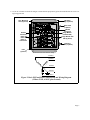
8. Use an AC voltmeter to check all voltages to ensure that the proper unit type has been installed for the service rating being protected.
0RXQWLQJ
+ROHSODFHV
0RXQWLQJ
)ODQJHSODFHV
'RRU/DWFK
SODFHV
1(875 $/
*URXQG
&RQQHFWRU
3KDVH$
3KDVH%
3KDVH&
&RQQHFWRUV
1HXWUDO
&RQQHFWRU
6XUJH0RGXOH
ZLWKRXW/('
*5281 '
6XUJH0RGXOHZLWK
/('SODFHV
3+$6($
3+$6(%
5HWDLQLQJ
6FUHZSODFHV
3+$6(&
)XVH
SODFHV
Not to exact scale. Door remove for clarity.
Phase A
Phase B
Neutral
Ground
Phase C
)LJXUH%DVLF30DQG30&RQILJXUDWLRQDQG:LULQJ'LDJUDP
3KDVH:<(:LUHSOXV*URXQG
Page 7
Disconnect Switch Option
All APC modular series SPDs can be equipped with an optional internal disconnect switch (Figure 3). The disconnect
switch provides a means to de-energize the entire suppressor, to facilitate servicing of unit’s components. (See Warning regarding the Neutral when testing the distribution system).
NOTE: A disconnect switch will add length, which increases the response time and the clamp voltage. To minimize
the additional lead length and optimize performance, units are available with an optional internal disconnect switch.
The disconnect switch is not a device that can be added to the unit after purchase. It must be ordered with the unit as
the mounting cabinet is larger for units having the option.
1(875 $/
&
1
%
$
$ % 1 &
If an internal disconnect switch is to be used, the location of the SPD and the disconnect switch should be planned
out carefully to avoid excessive lead length when wiring the devices.
'LVFRQQHFW
2SWLRQ
)LJXUH%DVLF30DQG30&RQILJXUDWLRQZLWK'LVFRQQHFW6ZLWFK2SWLRQ
'DXJKWHUERDUGIRU2SWLRQDO6XUJH&RXQWHU6KRZQ
Page 8
:$51,1*
0$,17(1$1&(2)7+,6685*(3527(&7,9('(9,&(6+28/'%(3(5)250('%<
48$/,),('3(56211(/21/<
'85,1*1250$/23(5$7,21+$=$5'28692/7$*(6$5(35(6(17,16,'(7+(81,7
:+(16(59,&,1*7+,681,7%(685(72)2//2:$//(/(&75,&$/6$)(7<35(&$8
7,216
$//32:(56285&(6727+,681,76+28/'%(/2&.('2))%()25(6(59,&,1*
7+,6:,//35(9(177+(5,6.2)5(&(,9,1*$1(/(&75,&$/6+2&.
Operation and Features
SPD’s do not require alot of operator intervention after installation.
NOTE: The PM Series has a green LED for each phase which extinguishes when the module is no longer providing
protection (fault condition).
All of the PM series of SPDs contain a diagnostic circuit which monitors the suppressors status continuously and
automatically. If a fault condition were to occur, the built-in front panel audible alarm will sound and a red "Service"
LED will light, indicating that the unit is in need of service by a qualified technician.
The audible alarm can be silenced by pressing the "Mute Alarm" button on the touchpad, until a qualified electrician
or service person is available to service the unit. The red "Service" LED will continue to be illuminated even though
the audible alarm has been silenced. This will continue until the fault condition has been cleared.
Each of the internal surge protection modules have a green LED that lights to signify that the module is on-line and
functioning properly (the N-G module does not have an LED). In addition to module LED’s, the front panel also displays the status of each internal module by use of diagnostically controlled green LED’s. This technique ensures that
a false indication does not occur if an LED were to burn out. A true/hard fault condition can be confirmed by having
an audible alarm with the red "Service" LED lit, as well any module LED and front panel status LED extinguished.
By utilizing all of these built in diagnostic features, an operator can more easily determine if a hard fault exists or if a
status LED is faulty. If power is applied to the SPD and one or more of the module LED’s are extinguished and any
diagnostic LED on the front panel concurs with any module LED, then the faulted module may need to be replaced.
Use the troubleshooting section of this manual to locate and repair the fault.
Page 9
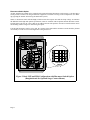
Status Panel Controls, Indicators, and Alarms
$OOLQGLFDWRUVDQGFRQWUROVDUHORFDWHGRQWKHIURQWGLDJQRVWLFSDQHO)LJXUHRIWKH6'3XQLW(DFKSKDVHIHDWXUHVD
WULFRORU/('LQGLFDWRU*UHHQLQGLFDWHVFRUUHFWRSHUDWLRQ$PEHULQGLFDWHVUHGXFHGSURWHFWLRQ5HGLQGLFDWHVORVVRI
SURWHFWLRQ,IDQLQRSHUDWLYHFRQGLWLRQZHUHWRRFFXUWKHEXLOWLQDXGLEOHDODUPZLOOVRXQGDQGWKHUHG6HUYLFH/('
ZLOOLOOXPLQDWH7KLVLQGLFDWHVWKDWWKHXQLWQHHGVHYDOXDWLRQE\DTXDOLILHGHOHFWULFLDQRUWHFKQLFLDQ8QWLODTXDOLILHG
SHUVRQHYDOXDWHVWKHXQLWSUHVVWKH0XWH$ODUPWRXFKSDGWRVLOHQFHWKHDODUP7KH/('LQGLFDWRUDERYHWKH0XWH
$ODUP WRXFKSDG LOOXPLQDWHV ZKHQ WKH DODUP LV GHDFWLYDWHG 1RUPDO RSHUDWLRQ RFFXUV ZLWK WKH 0XWH $ODUP /('
H[WLQJXLVKHG7KHUHG6HUYLFH/('ZLOOUHPDLQLOOXPLQDWHGHYHQWKRXJKWKH$XGLEOH$ODUPKDVEHHQVLOHQFHG7KH
7HVWWRXFKSDGWHVWVWKHUHG6HUYLFH/('DQGWKH$XGLEOH$ODUP
,I/('VDUHLOOXPLQDWHGLQDPDQQHUWKDWVXJJHVWVFRQWUDGLFWRU\LQIRUPDWLRQWKHUHPD\EHDQLQWHUQDOORJLFSUREOHP
DQGWKHXQLWQHHGVUHSODFHPHQW,IQRQHRIWKH/('VDUHLOOXPLQDWHGWKHXQLWPD\QRWEHLQVWDOOHGFRUUHFWO\3OHDVH
QRWHWKDWWKHLQWHUQDOVWRUDJHFDSDFLWRUIRUVXUJHFRXQWHUEDFNXSPXVWEHHQHUJL]HGIRUDERXWPLQXWHVEHIRUHWKH
³FRXQW´ SXVK EXWWRQ ZLOO IXQFWLRQ ,I D JUHHQ /(' LV QRW LOOXPLQDWHG DQG LV VXVSHFW RI EHLQJ IDXOW\ D TXDOLILHG
HOHFWULFLDQRUWHFKQLFLDQPD\DWWHPSWWRGLDJQRVHWKHSUREOHPE\GHHQHUJL]LQJWKHXQLWUHPRYLQJWKHIURQWFRYHUDQG
H[FKDQJLQJULEERQFDEOHOHDGVZLWKDQRWKHUSKDVHLIDYDLODEOH8SRQUHHQHUJL]LQJWKH63'WKHDSSURSULDWH/('
ZLOOLOOXPLQDWHLIWKHVXVSHFW/('KDVIDLOHG,IWURXEOHVKRRWLQJLQGLFDWHVDIDLOHG/('SOHDVHFRQWDFW$3&7HFKQLFDO
6XSSRUWDW$3&
6XUJH$UUHVW30
5
Test: Tests the red Service LED and audible alarm
Count: Increments the optional surge counter by one.
3KDVH$
3KDVH%
3KDVH&
6HUYLFH
7HVW
&RXQW
5HVHW
Reset: Resets the optional surge counter.
Mute Alarm: Turns the Alarm off. (Note that the
alarm is de-activated when the LED is lit).
6XUJH&RXQWHU
0XWH
$ODUP
Phase A, B, and C: Tri-color LED status indicators:
Green = Full protection
Amber = Partial protection
Red = No protection
Service: LED illuminates for any amber or red indication.
Surge Counter: Displays the total number of surges
encountered by the SPD.
)LJXUH6WDWXV3DQHOZLWK6XUJH&RXQWHU2SWLRQ
Surge Counter Option
In units so equipped, the surge counter option provides a means to total the number of transient voltage surges
encountered since the counter was last reset. The surge counter circuitry includes a "supercap". This will provide
power up to four days to retain memory should a power outage occur. NOTE: There is a 10 - 15 minute charging
cycle once power is connected, before the surge counter operates. The Surge Counter registers the sum of L-N and LG transient surges. There are Count and Reset touchpads. Pressing the Count touchpad increments the counter by
one. Pressing the Reset touchpad resets the counter to zero count.
Page 10
Dry Contacts Option
The Dry Contacts option utilize a DB-9 connector. This feature provides two sets of both normally open (NO) and
normally closed (NC) contacts through the DB-9 connector. These relay contacts can be used for remote indication
of the SPD’s operating status by changing state when there is an alarm condition. Examples could include a computer
interface board, an emergency management system, etc. The relay contact pin arrangement is defined in Table 3.
(Please note the jumpered connections. Pins 7, 8, & 9 do not represent a third set of contacts)
7DEOH5HOD\&RQWDFW3LQ$UUDQJHPHQW
3LQ
&RQWDFW7\SH
1RUPDOO\&ORVHG
&RPPRQ
1RUPDOO\2SHQ
1RUPDOO\&ORVHG
&RPPRQ
1RUPDOO\2SHQ
For custom applications using Dry Contacts, please note the following information: The Dry Contacts are designed
for low voltage or control signals only. Maximum switching current is 1 amp. Maximum switching voltage is 24
volts, DC or AC. Higher energy application may require additional relay implementation outside the PM. Damage to
the PM’s relay caused by implementation with energy levels in excess of those discussed in this manual will not be
covered by warranty.
Corrective Maintenance (Repair)
Surge Protection Devices (SPD) are designed for years of reliable, trouble-free operation. Unfortunately, even the
most reliable equipment can fail.
Built-in diagnostics are an integral part of the SPD and will aid in isolating which of the protection module(s) have
failed. To keep the SPD operating at peak performance, replacement of any bad module should be performed according to surge module removal and replacement instructions at the earliest service opportunity.
If a single module on a particular phase fails, the fuse takes the module off-line. It is recommended by APC that if a
module fails on any specific phase, that all modules be replaced at the same time, according to module removal
instructions that follow.
Standard troubleshooting procedures should be used to isolate other problems not associated with failed modules.
See Figure 5 (Troubleshooting Flowchart) for assistance. Replace bad components with identically rated parts to
continue proper operation and safety. It is very important that fuses be replaced with the exact fuse specified on
the fuse replacement warning label shipped with each unit. This label is found on the SPD mounting plane.
After all failed modules have been replaced, prior to returning power, inspect the entire SPD for other damaged components and replace as necessary. Table 4 lists typical replacement parts.
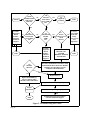
Troubleshooting
7URXEOHVKRRWLQJRIDQ63'FRQVLVWVRISHUIRUPLQJWKHVHTXHQFHRIVWHSVSURYLGHGLQWKH7URXEOVKRRWLQJ)ORZ&KDUW
LQ)LJXUH3HUIRUPWKHVWHSVLQWKLVFKDUWRQO\WRWKHH[WHQWQHFHVVDU\WRFOHDUWKHIDXOW
Page 11
$ODUP
$XGLEOH9LVXDO
5HG6HUYLFH
/('/LW"
67$57
1R
<HV
3RVVLEOH
'LDJQRVWLFV
%RDUG
)DLOXUH
&DOO$3&
7HFKQLFDO
6XSSRUW
<HV
$OO
,QWHUQDO
)URQW3DQHO
*UHHU/('V
/LW"
1R
$SSDUHQW
3UREOHP
<HV
(1'
1R
$OO
,QWHUQDO
)URQW3DQHO
*UHHQ/('V
/LW"
1R
$UH
$OO,QWHUQDO
0RGXOH
/('V
/LW"
1R
&RUUHFW
,V
3RZHU8WLOLW\
6HUYLFH
1R )HHGDQG
9ROWDJH&RUUHFW
9HULI\
RQDOO
3RZHU/HYHOV
3KDVHV"
DQG
2SHUDWLRQ
$3&
3RVVLEOH
'LDJQRVWLFV
%RDUG
)DLOXUH
&DOO$3&
7HFKQLFDO
6XSSRUW
(1'
:$51,1*
6(&85($//
32:(5
5(029(32:(5
727+(63'
'LVFRQQHFWDOO:+,7(1HXWDO:LUHVIURP
3&%7HUPLQDOVWKHQ&KHFN$//0RGXOHV
DQG)XVHVIRU2SHQ6KRUW&LUFXLW
&RQGLWLRQVZLWK2+00HWHU
$UH
0RGXOHV
6KRUWHG"
1R
<HV
5HSODFH)XVHV
5HSODFH%DG0RGXOHV
)XVHVDQGDQ\RWKHU
0RGXOHVRQWKH6DPH3KDVH
3URSHU
2SHUDWLRQ"
(QHUJL]H63'DQG9HULI\3URSHU2SHUDWLRQ
63'1RW2SHUDWLQJ3URSHUO\"
1R
(1'
3RVVLEOH'LDJQRVWLF%RDUG)DLOXUH
&DOO$3&7HFKQLFDO6XSSRUW
$3&
)LJXUH7URXEOHVKRRWLQJ)ORZ&KDUW
3DJH
(1'
:$51,1*
0$,17(1$1&(2)7+,6685*(3527(&7,9('(9,&(6+28/'%(3(5)250('%<
48$/,),('3(56211(/21/<
'85,1*1250$/23(5$7,21+$=$5'28692/7$*(6$5(35(6(17,16,'(7+(81,7
:+(16(59,&,1*7+,681,7%(685(72)2//2:$//(/(&75,&$/6$)(7<35(&$8
7,216
$//32:(56285&(6727+,681,76+28/'%(/2&.('2))%()25(6(59,&,1*
7+,6:,//35(9(177+(5,6.2)5(&(,9,1*$1(/(&75,&$/6+2&.
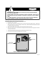
Display Board Removal & Replacement Instructions
7RUHPRYHWKH'LVSOD\ERDUGUHIHUWR)LJXUHDQGSURFHHGDVIROORZV
'LVFRQQHFWSRZHUWRWKH63'
2SHQWKHGRRURQWKHXQLWE\ORRVHQLQJWKHWZRVFUHZVWKDWVHFXUHWKHGRRUODWFKHVLQSODFH6OLGHWKHWRS
ODWFKXSZDUGDQGURWDWHLWVRWKDWLWQRORQJHUVHFXUHVWKHGRRU6OLGHWKHERWWRPODWFKGRZQZDUGDQGURWDWH
LWVRWKDWLWQRORQJHUVHFXUHVWKHGRRU
5HPRYHWKHQXWVWKDWVHFXUHWKHGLVSOD\ERDUGWRWKHSDQHOWKHQUHPRYHWKHERDUG
5HPRYHWKHFRQQHFWRUVRQHDWDWLPHIURPWKHH[LVWLQJERDUGDQGLQVHUWWKHPLQWRWKHDSSURSULDWHFRQQHFWRU
RQWKHUHSODFHPHQWERDUG
,QVWDOOWKHUHSODFHPHQWERDUGLQWRWKHSDQHOLQVWDOOWKHQXWVDQGWLJKWHQVHFXUHO\
&ORVHDQGVHFXUHWKHFDELQHWGRRUDQGDSSO\SRZHUWRWKH63'
'$ 1*(5
+,*+92/7$ *(
:$51,1*
Display Board
FOR CONTINUED PROTECTION
AGAINST RISK OF FIRE, REPLACE WITH
SAME TYPE AND RATING OF FUSE
Cabinet Door
(Cabinet not shown)
)LJXUH'LVSOD\%RDUG/RFDWRU'LDJUDP
3DJH
Diagnostic Board Removal and Replacement Instructions
To remove and replace the Diagnostic Board, refer to Figure 7 and proceed as follows:
1. Disconnect power to the SPD.
2. Remove the board from the standoffs.
3. Remove the connectors one at a time from the existing board and insert them into the appropriate connector
on the replacement board.
4. Install the replacement board onto the standoffs.
Diagnostic
Board
1 (8 75$ /
Cabinet Interior
(Door not shown)
&
1
%
$
)LJXUH'LDJQRVWLF%RDUG/RFDWRU'LDJUDP
Surge Module Removal and Replacement Instructions
Surge modules within the SPD may become damaged and require replacement. To remove and replace a surge module, refer to Figure 8 and proceed as follows:
1. Disconnect power to the SPD.
2. Open the door on the unit by loosening the two screws that secure the door latches in place. Slide the top
latch upward and rotate it so it no longer secures the door. Slide the bottom latch downward and rotate it so
that it no longer secures the door.
3. Remove the two allen-head screws that secure the surge module to the chassis.
4. Pull the surge module out of the chassis.
1RWHWKHORFDWLRQDQGSDUWQXPEHURIHDFKPRGXOHUHPRYHGDVWKLVLQIRUPDWLRQLVQRWVXSSOLHGHOVHZKHUHLQ
WKHFDELQHW
127(6XUJH0RGXOHVVKRXOGRQO\EHUHSODFHGZLWKDQHZPRGXOHKDYLQJWKHVDPHSDUWQXPEHUDVWKH
UHPRYHGPRGXOH
8QSDFNDQGLQVSHFWWKHUHSODFHPHQWVXUJHPRGXOHIRUGDPDJH,IWKHUHSODFHPHQWPRGXOHLVGDPDJHGFRQ
WDFW$3&7HFKQLFDO6XSSRUW
3DJH
$OLJQWKHUHSODFPHQWVXUJHPRGXOHZLWKWKHPRXQWLQJKROHVLQWKHFKDVVLV,QVWDOOWKHWZRDOOHQKHDGVFUHZV
UHPRYHGLQVWHSDQGWRUTXHWRLQFKSRXQGV
3RZHUXSWKH63'DQGYHULI\WKDWWKHJUHHQ/('LVOLWDQGWKDWDOODODUPVKDYHFOHDUHG
/(',QGLFDWRU
$OOHQ+HDG6FUHZ
SODFHV
6XUJH0RGXOH
,QVXODWRU
3DQHO
%DFNSODQH
$OOHQ+HDG6FUHZ
SODFHV
)LJXUH6XUJH0RGXOH5HPRYDODQG5HSODFHPHQW
Preventive Maintenance - Inspection and Cleaning
Inspection of the SPD should be performed periodically to maintain reliable system performance and continued transient voltage surge protection. While it is difficult to establish a preventive maintenance schedule because conditions
vary from location to location, inspections for failed modules and other signs of trouble utilizing the built-in diagnostics should be performed on a routine basis (weekly or monthly).
3DJH
Replacement Parts Listing
APC offers the items listed in Table 4 as field replaceable items.
7DEOH5HSODFHPHQW3DUWV/LVW
$3&0RGHO
1XPEHU
9ROWDJH6\VWHP
'HVFULSWLRQ
3DUW:RUNV:LWK
0
93KDVH:<(
96SOLW3KDVH
N$3KDVH0RGXOH
DOO303XQLWV
01
93KDVH:<(
96SOLW3KDVH
N$1*0RGXOH
DOO303XQLWV
0*
9
N$3KDVH0RGXOH
DOO30*XQLWV
0*1
9
N$1*0RGXOH
DOO30*XQLWV
0/
N$3KDVH0RGXOH
DOO30/XQLWV
0/1
N$1*0RGXOH
DOO30/XQLWV
0
93KDVH:<(
96SOLW3KDVH
N$3KDVH0RGXOH
DOO303XQLWV
01
93KDVH:<(
96SOLW3KDVH
N$1*0RGXOH
DOO303XQLWV
0*
9
N$3KDVH0RGXOH
DOO30*XQLWV
0*1
9
N$1*0RGXOH
DOO30*XQLWV
0/
9
N$3KDVH0RGXOH
DOO30/XQLWV
0/1
9
N$1*0RGXOH
DOO30/XQLWV
5)
DOO
)XVHIRUDOOPRGXODUXQLWV
DOOPRGXODUXQLWV
'%
93KDVH:<(
96SOLW3KDVH
9ROW'LDJQRVWLF3&%
DOOPRGXODU30330)XQLWV
'%*
9
9ROW'LDJQRVWLF3&%
DOOPRGXODU30*XQLWV
'%/
9
9ROW'LDJQRVWLF3&%
DOOPRGXODU30/XQLWV
6%
DOO
6XUJH&RXQWHU3&%
DOOPRGXODUXQLWVZLWK6XUJH
&RXQWHU
'3%
DOO
'LVSOD\3&%
DOON$XQLWVZLWKRXW
6XUJH&RXQWHU
'3%6
DOO
'LVSOD\3&%ZLWK6XUJH&RXQWHU
DOON$XQLWVZLWK6XUJH
&RXQWHU
3DJH
Limited Warranty
APC warrants it’s AC panel protection products against defects in workmanship and materials for 5 years from the
date of original purchase. The panel protection device must be installed by a qualified and licensed electrician in
order to qualify for warranty proctection.
Liability is limited to the replacement of the defective product. A Return Material Authorization must be given by
APC prior to the return of any product (see Technical Support and Customer Service). A copy of the invoice from the
installer (electrician or electrical service company) must accompany the defective device being returned. If the return
of a device is authorized by APC, APC will immediately ship a replacement unit to the customer. Along with the
replacement unit, APC will include a pre-paid shipping tag for the return of the originally defective unit. The replacement unit will not be warranteed unless the defective unit is received by APC.
Under no circumstance is APC responsible for the cost of removal or installation of any panel protection device.
APC also offers unlimited replacement of modular and component parts within the warranty period previously
described.
The company specifically disclaims all other warranties, expressed or implied. Additionally, the company will not be
responsible for incidental or consequential damages resulting from any defect in any product or component thereof.
Technical Support and Customer Service
United States and Canada:
1-800-800-4APC
This manual, as well as information about the entire APC product line is available on the internet at: www.apc.com.
Prior to calling APC for technical assistance or ordering parts, please have the following information available:
Model Number of unit:
________________________________________________________
Serial Number of unit:
________________________________________________________
Manufacture Date:
________________________________________________________
Purchase Date:
________________________________________________________
Your Order Number:
________________________________________________________
Return Shipment Address
American Power Conversion Corporation
132 Fairgrounds Road
P.O. Box 278
West Kingston, Rhode Island 02892
USA
3DJH3DJH%ODQN