1
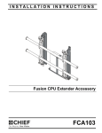
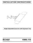
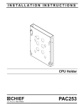
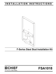
INSTALLATION INSTRUCTIONS
Instrucciones de instalación
Installationsanleitung
Instruções de Instalação
Istruzioni di installazione
Installatie-instructies
Instructions d´installation
CPU WALL MOUNT
Spanish Product Description
German Product Description
Portuguese Product Description
Italian Product Description
Dutch Product Description
French Product Description
KSA-1023
KSA-1023
Installation Instructions
DISCLAIMER
Milestone AV Technologies and its affiliated corporations and
subsidiaries (collectively "Milestone"), intend to make this
manual accurate and complete. However, Milestone makes no
claim that the information contained herein covers all details,
conditions or variations, nor does it provide for every possible
contingency in connection with the installation or use of this
product. The information contained in this document is subject
to change without notice or obligation of any kind. Milestone
makes no representation of warranty, expressed or implied,
regarding the information contained herein. Milestone assumes
no responsibility for accuracy, completeness or sufficiency of
the information contained in this document.
Chief® is a registered trademark of Milestone AV Technologies.
All rights reserved.
IMPORTANT WARNINGS AND
CAUTIONS!
CAUTION: A CAUTION alerts you to the possibility of
damage or destruction of equipment if you do not follow the
corresponding instructions.
WARNING: Failure to read, thoroughly understand, and
follow all instructions can result in serious personal injury,
damage to equipment, or voiding of factory warranty! It is the
installer’s responsibility to make sure all components are
properly assembled and installed using the instructions
provided.
WARNING: Failure to provide adequate structural strength
for this component can result in serious personal injury or
damage to equipment! It is the installer’s responsibility to
make sure the structure to which this component is attached
can support five times the combined weight of all equipment.
Reinforce the structure as required before installing the
component.
WARNING: Exceeding the weight capacity can result in
WARNING: A WARNING alerts you to the possibility of
serious injury or death if you do not follow the instructions.
serious personal injury or damage to equipment! It is the
installer’s responsibility to make sure the combined weight of
all components located between the KSA-1023 up to (and
including) the display/projector does not exceed 50 lbs (22.7
kg).
DIMENSIONS
149
5.87
MIN 1.75 [44.5]
MAX 3.75 [95.3]
224
8.83
2
Installation Instructions
KSA-1023
LEGEND
Tighten Fastener
Pencil Mark
Apretar elemento de fijación
Marcar con lápiz
Befestigungsteil festziehen
Stiftmarkierung
Apertar fixador
Marcar com lápis
Serrare il fissaggio
Segno a matita
Bevestiging vastdraaien
Potloodmerkteken
Serrez les fixations
Marquage au crayon
Loosen Fastener
Drill Hole
Aflojar elemento de fijación
Perforar
Befestigungsteil lösen
Bohrloch
Desapertar fixador
Fazer furo
Allentare il fissaggio
Praticare un foro
Bevestiging losdraaien
Gat boren
Desserrez les fixations
Percez un trou
Phillips Screwdriver
Adjust
Destornillador Phillips
Ajustar
Kreuzschlitzschraubendreher
Einstellen
Chave de fendas Phillips
Ajustar
Cacciavite a stella
Regolare
Kruiskopschroevendraaier
Afstellen
Tournevis à pointe cruciforme
Ajuster
Open-Ended Wrench
Remove
Llave de boca
Quitar
Gabelschlüssel
Entfernen
Chave de bocas
Remover
Chiave a punte aperte
Rimuovere
Steeksleutel
Verwijderen
Clé à fourche
Retirez
By Hand
Optional
A mano
Opcional
Von Hand
Optional
Com a mão
Opcional
A mano
Opzionale
Met de hand
Optie
À la main
En option
Hex-Head Wrench
Security Wrench
Llave de cabeza hexagonal
Llave de seguridad
Sechskantschlüssel
Sicherheitsschlüssel
Chave de cabeça sextavada
Chave de segurança
Chiave esagonale
Chiave di sicurezza
Zeskantsleutel
Veiligheidssleutel
Clé à tête hexagonale
Clé de sécurité
3
KSA-1023
Installation Instructions
TOOLS REQUIRED FOR INSTALLATION
1/2" (12.7mm) (steel stud or drywall)
7/64" (2.8mm) (wood stud)
#2
1/8"
(only if mounting to KSA-1022)
PARTS
C(2)
A(1)
B(1)
E(2)
1/4-20 x 1 1/2"
D(2)
1/4-20"
4
F(2)
#10-24 x 1/2"
G(2)
#12 x 2 1/2"
Installation Instructions
KSA-1023
Site Requirements for Using Steel Studs
WARNING: IMPROPER INSTALLATION CAN LEAD TO EQUIPMENT FALLING CAUSING SERIOUS PERSONAL INJURY
OR DAMAGE TO EQUIPMENT! The figure below identifies the minimum requirements for installation of display mounts onto a
steel stud structure. If the structure or its components do not meet these requirements contact the mount manufacturer for specific
instructions before attempting installation. It should also be noted that no other equipment should be mounted to the same stud.
16" or 24" (on center) Studs
Mount Installation Location
(Must be centered on stud)
If back side of wall is unfinished, drywall must be installed
to a minimum of one stud left and right of the stud(s)
being used to install the mount. Drywall must be
secured to studs with screws 12" on center
There must be a minimum of
1 7/8" (48mm) clearance
inside wall
FRONT
Drywall
**1/2"
minimum Drywall
Thickness
(Both Sides of Stud)
**See Hazard statement
on page 2!
Steel Stud (2 x 4 / 25ga minimum)
Stud type and structural strength must conform to the North American
Specification for the Design of Cold-Formed Steel Structural Members.
[362 S 125 18, C-Shaped, S-Stud Section]
Figure 1
5
KSA-1023
Installation Instructions
Assembly And Installation
8.
Slide plastic cap on anchor (D) towards wall until flange of
cap is flush with wall. (See Figure 4)
Attach to Wall Using Steel Studs or Drywall
After determining the site meets the installation requirements:
1.
2.
3.
Steel Stud
Identify desired mounting location on wall.
Using a stud finder or similar method locate stud.
Align mounting holes in CPU wall plate (A) with stud making
sure mounting holes are centered on stud. (See Figure 2)
Drywall
Plastic Cap
WARNING: IMPROPER INSTALLATION CAN LEAD TO
EQUIPMENT FALLING CAUSING SERIOUS PERSONAL
INJURY OR DAMAGE TO EQUIPMENT!
4.
Mark location of two mounting holes on wall using the wall
plate as a template. Mark holes where the top and bottom
holes of the bracket will be connected. (See Figure 2)
5.
8
(D) x 2
Drill two 1/2" holes. (See Figure 2)
7
Anchor Metal Channel
(Side View)
5
Figure 4
9.
Snap off plastic straps on anchor at wall by pushing side to
side, snapping off straps level with flange of plastic cap.
(See Figure 5)
10. Repeat steps 6 through 9 for remaining mounting hole.
4
Steel Stud
Drywall
9
Plastic Cap
must be centered on stud
Plastic Straps
Figure 2
6.
Hold metal channel on anchor (D) flat alongside plastic
straps and slide channel through hole. (See Figure 3)
Anchor Metal Channel
(SIDE VIEW)
Drywall
Plastic Straps
6
(D) x 2
Figure 3
7.
6
Holding plastic straps on anchor (D), pull anchor away from
wall until channel rests flush behind wall making sure
anchor channel is positioned vertically on stud. (See Figure
4)
Figure 5
11. Place CPU mounting plate (A) over anchors and align
mounting holes in display mount with holes in anchors. (See
Figure 6)
12. Insert 1/4-20 x 1-1/2" Phillips flat machine screw (E) into
mounting hole on CPU mounting plate (A) and into anchor
(D) and tighten until flush against mounting plate. DO NOT
overtighten! (See Figure 6)
13. Repeat steps 11 through 13 for remaining mounting hole.
Installation Instructions
KSA-1023
Attach to Wall Track Accessory
NOTE: The KSA-1023 CPU Wall Mount can be mounted on the
Steel Stud
KSA-1022 Wall Track Accessory. Refer to KSA-1022
installation manual for specific weight limits for the
accessory.
Drywall
12
(E) x 2
1.
Attach wall track accessory to wall according to wall track
accessory installation manual.
2.
Install two #10-24 x 1/2" flat head cap screw (F) through
upper holes on CPU wall mount plate (A) into holes on wall
track accessory brackets. (See Figures 8 and 9)
Wall track accessory
(not included)
(A)
Anchor Metal Channel
(SIDE VIEW)
2
(F) x 2
Figure 6
Attach to Wall Using Wood Studs
1.
Determine location for mount keeping in mind CPU size and
safety requirements.
2.
Using the CPU wall mount plate (A) as a template, mark and
then drill two 7/64" diameter pilot holes through the lower
holes of CPU wall mount plate into wall structure. (See
Figure 7)
3.
Install two #12 x 2 1/2" Phillips flat wood screws (G) through
CPU Wall Mount Plate and into holes. (See Figure 7)
3
(G) x 2
(horizontal wall track)
Figure 8
2
2
(F) x 2
(vertical wall track)
Figure 7
Figure 9
7
KSA-1023
Installation Instructions
CPU Installation
1.
Set CPU Support Bracket (B) on top of CPU Wall Mount
Plate (A). (See Figure 10)
2.
Use knobs (C) to secure CPU Support Bracket (B) to CPU
Wall Mount Plate (A). (See Figure 10)
3
Figure 11
2
4.
Loosen knobs (C) below CPU Wall Mount in order to allow
adjustment.
5.
Collapse the mount until it fits tightly around CPU. (See
Figure 12)
(C) x 2
Figure 10
5
WARNING: Exceeding the weight capacity can result in
serious personal injury or damage to equipment! It is the
installer’s responsibility to make sure the combined weight of
all components located between the KSA-1023 up to (and
including) the display/projector does not exceed 50 lbs (22.7
kg).
3.
Insert CPU into CPU Wall Mount. (See Figure 11)
NOTE: Center CPU on the mount to ensure weight of CPU is
evenly distributed.
6
(C) x 2
(side view)
Figure 12
6.
8
Tighten knobs (C) below CPU Wall Mount to secure plate in
position. (See Figure 12)
Installation Instructions
KSA-1023
9
KSA-1023
10
Installation Instructions
Installation Instructions
KSA-1023
11
KSA-1023
Installation Instructions
USA/International
Europe
Chief Manufacturing, a products division
of Milestone AV Technologies
8834-000010
©2008 Milestone AV Technologies, a
Duchossois Group Company
www.chiefmfg.com
12/08
Asia Pacific
A
P
F
A
P
F
A
8401 Eagle Creek Parkway, Savage, MN 55378
800.582.6480 / 952.894.6280
877.894.6918 / 952.894.6918
Fellenoord 130 5611 ZB EINDHOVEN, The Netherlands
+31 (0)40 2668620
+31 (0)40 2668615
Room 24F, Block D, Lily YinDu International Building
LuoGang, BuJi Town, Shenzhen, CHINA.
P +86-755-8996 9226
F +86-755-8996 9217