1
INSTALLATION INSTRUCTIONS
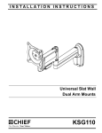
Universal Slat Wall
Dual Arm Mounts
KSG110
KSG110
Installation Instructions
DISCLAIMER
CSAV, Inc., and its affiliated corporations and subsidiaries
(collectively, "CSAV"), intend to make this manual accurate and
complete. However, CSAV makes no claim that the information
contained herein covers all details, conditions or variations, nor
does it provide for every possible contingency in connection
with the installation or use of this product. The information
contained in this document is subject to change without notice
or obligation of any kind. CSAV makes no representation of
warranty, expressed or implied, regarding the information
contained herein. CSAV assumes no responsibility for
accuracy, completeness or sufficiency of the information
contained in this document.
IMPORTANT WARNINGS AND
CAUTIONS!
WARNING: A WARNING alerts you to the possibility of
serious injury or death if you do not follow the instructions.
CAUTION: A CAUTION alerts you to the possibility of
damage or destruction of equipment if you do not follow the
corresponding instructions.
DIMENSIONS
2
WARNING: Failure to read, thoroughly understand, and
follow all instructions can result in serious personal injury,
damage to equipment, or voiding of factory warranty! It is the
installer’s responsibility to make sure all components are
properly assembled and installed using the instructions
provided.
WARNING: Failure to provide adequate structural strength
for this component can result in serious personal injury or
damage to equipment! It is the installer’s responsibility to
make sure the structure to which this component is attached
can support five times the combined weight of all equipment.
Reinforce the structure as required before installing the
component.
WARNING: Exceeding the weight capacity can result in
serious personal injury or damage to equipment! It is the
installer’s responsibility to make sure the combined weight of
all components located between the supporting structure and
mount does not exceed the 40 lbs (18.14 kg).
Installation Instructions
KSG110
LEGEND
Tighten Fastener
Pencil Mark
Apretar elemento de fijación
Marcar con lápiz
Befestigungsteil festziehen
Stiftmarkierung
Apertar fixador
Marcar com lápis
Serrare il fissaggio
Segno a matita
Bevestiging vastdraaien
Potloodmerkteken
Serrez les fixations
Marquage au crayon
Loosen Fastener
Drill Hole
Aflojar elemento de fijación
Perforar
Befestigungsteil lösen
Bohrloch
Desapertar fixador
Fazer furo
Allentare il fissaggio
Praticare un foro
Bevestiging losdraaien
Gat boren
Desserrez les fixations
Percez un trou
Phillips Screwdriver
Adjust
Destornillador Phillips
Ajustar
Kreuzschlitzschraubendreher
Einstellen
Chave de fendas Phillips
Ajustar
Cacciavite a stella
Regolare
Kruiskopschroevendraaier
Afstellen
Tournevis à pointe cruciforme
Ajuster
Open-Ended Wrench
Remove
Llave de boca
Quitar
Gabelschlüssel
Entfernen
Chave de bocas
Remover
Chiave a punte aperte
Rimuovere
Steeksleutel
Verwijderen
Clé à fourche
Retirez
By Hand
Optional
A mano
Opcional
Von Hand
Optional
Com a mão
Opcional
A mano
Opzionale
Met de hand
Optie
À la main
En option
Hex-Head Wrench
Security Wrench
Llave de cabeza hexagonal
Llave de seguridad
Sechskantschlüssel
Sicherheitsschlüssel
Chave de cabeça sextavada
Chave de segurança
Chiave esagonale
Chiave di sicurezza
Zeskantsleutel
Veiligheidssleutel
Clé à tête hexagonale
Clé de sécurité
3
KSG110
Installation Instructions
TOOLS REQUIRED FOR INSTALLATION
3/16"
(Provided)
5/32"
(Provided)
PARTS
A (1)
B (1)
E (1)
C (1)
3/16"
D (1)
5/32"
G1
G5
G2
F (2)
8-32 x 3/8"
G4
G3
G (1)
4
Installation Instructions
KSG110
INSTALLATION
B
WARNING: FAILURE TO PROVIDE ADEQUATE
STRUCTURAL STRENGTH FOR THIS COMPONENT CAN
RESULT IN SERIOUS PERSONAL INJURY OR DAMAGE
TO EQUIPMENT! It is the installer’s responsibility to make
sure the structure to which this component is attached can
support five times the combined weight of all equipment.
Reinforce the structure as required before installing the
component.
1.
Install the slat wall bracket (B) following the instructions
included with kit.
IMPORTANT ! : If the display being installed has a recessed
mounting surface, the display must be assembled to the mount
prior to mount installation. See Display Installation in this
document before proceeding.
2.
3
A
Insert top of mount (A) over lip on top of wall bracket (B).
(See Figure 1)
Figure 2
4.
A
Tighten set screw using 5/32" hex key (D). (See Figure 3)
CAUTION: IMPROPER INSTALLATION CAN LEAD TO
DISPLAY FALLING CAUSING SERIOUS PERSONAL
INJURY OR DAMAGE TO EQUIPMENT! Make sure set
screw engages back side of mounting dish on wall bracket
(B). (See Figure 3)
2
A
B
B
4
Figure 1
3.
Swing mount (A) down flush against wall bracket (B). (See
Figure 2)
Figure 3
DISPLAY INSTALLATION
The mounting holes on the back of the display will be flush with
the back surface, or recessed into the back. Refer to the
applicable installation procedure below.
Swing Arm Flush Display Installation
CAUTION: IMPROPER INSTALLATION CAN LEAD TO
DISPLAY FALLING CAUSING SERIOUS PERSONAL
INJURY OR DAMAGE TO EQUIPMENT! Using screws of
improper size may damage your display! Proper screws will
easily and completely thread into display mounting holes.
5
KSG110
Installation Instructions
CAUTION: IMPROPER INSTALLATION CAN LEAD TO
DISPLAY FALLING CAUSING SERIOUS PERSONAL
INJURY OR DAMAGE TO EQUIPMENT! Inadequate thread
engagement in display may cause display to fall! Back out
screws ONLY as necessary to allow installation of Centris
bracket!
1.
2.
3.
Centris Cup
4
Ensure Centris cup is able to swivel and tilt easily, yet still
be tight enough to hold display in desired position. Adjust
as required before proceeding. See "ADJUSTMENT" for
detail.
Using Phillips screwdriver, carefully install two screws (G1)
into the upper mounting holes on the display. Thread
screws completely into display, then back out 3 complete
turns.
Align two screws (G1) (installed on the back of the display
in the previous step) with the two top teardrop mounting
holes on the Centris cup.
G1 x 2
Figure 5
6.
CAUTION: IMPROPER INSTALLATION CAN LEAD TO
DISPLAY FALLING CAUSING SERIOUS PERSONAL
INJURY OR DAMAGE TO EQUIPMENT! Smaller area of
teardrop mounting holes must be facing downward for proper
installation. Reposition Centris cup if required.
G1 x 2
2
Proceed to "CABLE MANAGEMENT."
Swing Arm Recessed Display Installation
1.
Ensure Centris bracket is able to swivel and tilt easily, yet
still be tight enough to hold display in desired position.
Adjust as required before proceeding. See
"ADJUSTMENT" for detail.
2. Carefully place display face down on a clean and dry
surface.
3. Determine depth of recessed mounting holes relative to
back surface of display.
4. Select proper length spacer and screw from table below:
IMPORTANT ! : All spacers used should be the same length.
If the recess depths result in multiple spacer lengths, then
select the longer spacer.
IF recess DEPTH is: THEN use spacer:
3
3/8" or less
G4 (3/8" long)
G2 (G4 x 20mm)
More than 3/8" up to
and including 3/4"
G5 (3/4" long)
G3 (G4 x 30mm)
5.
Centris Cup
6.
Figure 4
4.
5.
Using Phillips screwdriver, install two screws (G1) through
the lower mounting holes in Centris cup into the display.
Tighten all screws (G1). Do not overtighten!
Place the four (G4 or G5) spacers over each mounting hole
on the back of display. (See Figure 6)
Orient mount so that mounting holes in the Centris cup are
aligned with the holes in the spacers (G4 or G5); rotate the
Centris cup as required (See Figure 6).
CAUTION: IMPROPER INSTALLATION CAN LEAD TO
DISPLAY FALLING CAUSING SERIOUS PERSONAL
INJURY OR DAMAGE TO EQUIPMENT! Using screws of
improper size may damage your display! Proper screws will
easily and completely thread into display mounting holes.
7.
8.
9.
6
AND screw:
Using Phillips screwdriver, install four screws (G2 or G3)
through the mounting holes in Centris cup, through the
spacers (G4 or G5), into display (See Figure 6).
Tighten all four screws. Do not overtighten!
Return to mount installation section to continue.
Installation Instructions
KSG110
Centris Cup
7
5
G2 or G3
(4 places)
G4 or G5
(4 places)
Cable Management
Bracket (in open position)
Cable Path (typical)
NOTE: Display not shown for clarity.
Figure 8
4.
Figure 6
Close cable management bracket by sliding it back towards
the centerline of the arm (See Figure 7).
NOTE: If necessary, cable management bracket attach screws
Cable Management
may be tightened using hex key.
1.
Attach all cables to display.
2.
Open the cable management bracket by sliding it towards
the edge of the arm (See Figure 7).
CAUTION: Ensure that adequate cable slack exists for
movement of display, and that cables will not be pinched by
installation of cover (E) or screws (F).
NOTE: If necessary, cable management bracket attach screws
may be loosened using hex key.
5.
Carefully insert cables in cavity located in lower portion of
mount arm (See Figure 9).
6.
Using Phillips screwdriver, install cover (E) with two
screws (F).
Attach
Screws
Cable Path
(typical)
CLOSED Position
OPEN Position
View from Bottom
Figure 7
E
CAUTION: Ensure that adequate cable slack exists for
Fx2
movement of display, and that cables will not be pinched
when bracket is closed.
3.
Carefully insert cables into bracket (See Figure 8).
Figure 9
Installation is complete.
Adjustments
Centris Head Tension Adjustment
1. If previously attached, disconnect cables from
display, remove display.
7
KSG110
Installation Instructions
2. Using Phillips screwdriver, slightly loosen or tighten
the adjustment screw as necessary (See Figure 10).
Adjustment Screw
2
Figure 10
3. Reinstall display. See Display Installation in this
document.
Display Adjustment
Lateral position on display:
1.
Using your fingers, slightly loosen adjustment knob "A".
(See Figure 11)
2. Slide display to desired position.
3. Using your fingers, tighten adjustment knob "A". (See
Figure 11)
PITCH / YAW / ROLL Tension
1.
2.
3.
Using your fingers, slightly loosen adjustment knob "B".
(See Figure 11)
Adjust display as desired.
Using your fingers, tighten adjustment knob "B".
A B
Figure 11
Swing Arm Tension
1.
8
Using 3/16" hex wrench (C), loosen or tighten adjustment
screw(s) as necessary (See Figure 12).
Figure 12
Installation Instructions
KSG110
9
KSG110
Installation Instructions
USA/International
Europe
Asia Pacific
8832-000237
2007 Chief Manufacturing
www.chiefmfg.com
08/07
A
P
F
A
P
F
A
8401 Eagle Creek Parkway, Savage, MN 55378
800.582.6480 / 952.894.6280
877.894.6918 / 952.894.6918
Fellenoord 130 5611 ZB EINDHOVEN, The Netherlands
+31 (0)40 2668620
+31 (0)40 2668615
Room 30I, Block D, Lily YinDu International Building
LuoGang, BuJi Town, Shenzhen, CHINA. Post Code: 518112
P +86-755-8996 9226 ; 8996 9236 ; 8996 9220
F +86-755-8996 9217