1
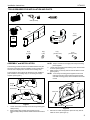
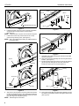
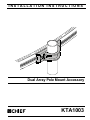
INSTALLATION INSTRUCTIONS
Instrucciones de instalación
Installationsanleitung
Instruções de Instalação
Istruzioni di installazione
Installatie-instructies
Instructions d´installation
Dual Array Pole Mount Accessory
Spanish Product Description
German Product Description
Portuguese Product Description
Italian Product Description
Dutch Product Description
French Product Description
KTA1003
KTA1003
Installation Instructions
DISCLAIMER
CSAV, Inc., and its affiliated corporations and subsidiaries
(collectively, "CSAV"), intend to make this manual accurate and
complete. However, CSAV makes no claim that the information
contained herein covers all details, conditions or variations, nor
does it provide for every possible contingency in connection
with the installation or use of this product. The information
contained in this document is subject to change without notice
or obligation of any kind. CSAV makes no representation of
warranty, expressed or implied, regarding the information
contained herein. CSAV assumes no responsibility for
accuracy, completeness or sufficiency of the information
contained in this document.
IMPORTANT WARNINGS AND
CAUTIONS!
WARNING: A WARNING alerts you to the possibility of
WARNING: Failure to read, thoroughly understand, and
follow all instructions can result in serious personal injury,
damage to equipment, or voiding of factory warranty! It is the
installer’s responsibility to make sure all components are
properly assembled and installed using the instructions
provided.
WARNING: Failure to provide adequate structural strength
for the installation of this kit can result in serious personal
injury or damage to equipment! It is the installer’s
responsibility to make sure the structure to which this mount
is attached can support five times the combined weight of all
equipment.
WARNING: Exceeding the weight capacity can result in
serious personal injury or damage to equipment! See the
installation instructions that came with the array onto which
this accessory is being installed for weight limits.
serious injury or death if you do not follow the instructions.
CAUTION: A CAUTION alerts you to the possibility of
damage or destruction of equipment if you do not follow the
corresponding instructions.
LEGEND
2
Tighten Fastener
Adjust
Apretar elemento de fijación
Ajustar
Befestigungsteil festziehen
Einstellen
Apertar fixador
Ajustar
Serrare il fissaggio
Regolare
Bevestiging vastdraaien
Afstellen
Serrez les fixations
Ajuster
Loosen Fastener
Hex-Head Wrench
Aflojar elemento de fijación
Llave de cabeza hexagonal
Befestigungsteil lösen
Sechskantschlüssel
Desapertar fixador
Chave de cabeça sextavada
Allentare il fissaggio
Chiave esagonale
Bevestiging losdraaien
Zeskantsleutel
Desserrez les fixations
Clé à tête hexagonale
Installation Instructions
KTA1003
TOOLS REQUIRED FOR INSTALLATION AND PARTS
.200" (Ø 5mm)
A (1)
B (1)
C (1)
(5/32")
I/M
x1
D (2)
(1/4-20)
E (4)
(1/4")
ASSEMBLY and INSTALLATION
The following procedures assume an additional base and pole
have been purchased and are available. The procedures also
assume that no displays are mounted to the existing array.
The KTA1003 is used to allow the attachment of an additional
pole and base to an existing array or connecting two arrays
together. (See Figure 1)
F (2)
(1/4-20 x 3/4")
G (2)
(1/4-20 x 7/8")
NOTE: Steps 1 and two do not apply if two arrays are being
joined together.
Loosen and remove end lock retaining screw and set aside
for reuse. (See Figure 2)
4. Slide end lock out of array channel and set aside for reuse.
(See Figure 2)
NOTE: If two arrays are being joined together the end lock
retaining screw and end lock must be removed from
ends that are being joined, and the hardware will not be
reused.
3.
Array
Single
Array
Dual Arrays
End Lock
Figure 1
1.
2.
Loosen four Button head cap screws securing existing pole
clamp to array.
Slide existing base towards left hand side of array
approximately halfway between middle and left hand Centris
cup.
Square Nut
Figure 2
5.
Remove two cable management clips from array and set
aside for reuse. (See Figure 3)
3
KTA1003
Installation Instructions
Array
(D) x 2
(E) x 2
(G) x 2
Cable Management Clip
(A) x 1
Figure 3
Figure 5
6.
Install two square nuts (D) into array channel and position
at approximate mounting location of second base.
(See Figure 4)
NOTE: Chamfered side of square nuts should be facing pole.
Array
7.
Install end lock into array channel and secure to array
channel using retaining screw. (See Figure 4)
NOTE: Step 7 only applies when adding an additional base to
one existing array.
(A) x 1
(C) x 1
Figure 6
9.
(D) x 2
Array
Assemble pole to base following the instructions provided
with the accessories.
10. Align pole of new base assembly with new array attachment
bracket . (See Figure 7)
11. Install two button head cap screws (F) and two flat washers
(E) through pole clamp (B) and into array attachment
bracket (A). (See Figure 7) and (See Figure 8)
Array
(A) x 1
(E) x 2
End Lock
(F) x 2
Array
(B) x 1
Square Nut
Figure 4
Figure 7
Align outer mounting holes in front array attachment bracket
(A) with two square nuts (D) in array channel(s) and secure
using two flat washers (E) and two button head cap screws
(G). (See Figure 5) and (See Figure 6)
NOTE: DO NOT tighten at this time!.
12. Secure pole clamp (B) to array attachment bracket (A) using
hex wrench (C) provided. DO NOT fully tighten at this time!
(See Figure 8)
8.
4
Installation Instructions
KTA1003
(A) x 1
Array
(A) x 1
(C) x 1
Figure 8
13. Slide base assemblies left or right and turn poles
accordingly to ensure bases are evenly spaced across
array and properly positioned.
(See Figure 9) and
(See Figure 10)
Array
Figure 9
Figure 10
14. Tighten all button head cap screws to secure array
attachment bracket(s) (A) to array(s) using 5/32" hex
wrench (C) provided.
15. Install displays following the installation instructions
provided with the array mount.
5
KTA1003
Installation Instructions
USA/International
Europe
Asia Pacific
8832-000225
2007 Chief Manufacturing
www.chiefmfg.com
05/07
A
P
F
A
P
F
A
8401 Eagle Creek Parkway, Savage, MN 55378
800.582.6480 / 952.894.6280
877.894.6918 / 952.894.6918
Fellenoord 130 5611 ZB EINDHOVEN, The Netherlands
+31 40 2668620
+31 (0) 40 2668615
Room 30I, Block D, Lily YinDu International Building
LuoGang, BuJi Town, Shenzhen, CHINA. Post Code: 518112
P +86-755-8996 9226 ; 8996 9236 ; 8996 9220
F +86-755-8996 9217