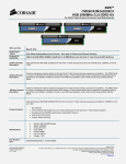
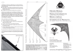
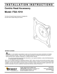
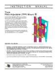
1
INSTALLATION INSTRUCTIONS
Horizontal Array Pole Clamp
Models: KTA-220/225 and KTA-320/325
The KTA-220/225 and KTA-320/325 pivot arrays allow
horizontal (yaw), vertical (pitch), and roll display
adjustment. The pitch adjustment range is 30° (15° up /
15° down).
The KTA is designed to mount two or three 17" displays.
The KTA accommodates standard VESA® 75mm/100mm
compliant displays.
KTA-220/225
KTA-320/325
BEFORE YOU BEGIN
CAUTION: To prevent damage to your display, which could affect or void the Factory warranty, thoroughly study all
instructions and illustrations before you begin to install the mount. Pay particular attention to the "Important Warnings
and Cautions" on Page 2.
CAUTION: The combined weight of the displays installed must not exceed 70 lbs (31.8 kg) for the KTA-220 and
KTA-225 and 90lbs (40.8 kg) for the KTA-320 and KTA-325, the maximum load capacity of the mounts. The weight of
each individual display must not exceed 35 lbs (15.9 kg) for the KTA-220 and KTA-225 or 30 lbs (13.6 kg) for the
KTA-320 and KTA-325.
CHIEF MANUFACTURING INC.
1-800-582-6480 952-894-6280 FAX 952-894-6918
8401 EAGLE CREEK PARKWAY, STE 700
SAVAGE, MINNESOTA 55378 USA
8832-000141 Rev E
©2008 Chief Manufacturing
www.chiefmfg.com
11/08
Models: KTA-220/225 and KTA-320/325
•
Installation Instructions
IMPORTANT WARNINGS AND CAUTIONS!
WARNING: A WARNING alerts you to the possibility of serious injury or death if you do not follow the instructions.
CAUTION: A CAUTION alerts you to the possibility of damage or destruction of equipment if you do not follow the
corresponding instructions.
WARNING: RISK OF ELECTRIC SHOCK ! Using the wrong screws could result in severe personal injury or damage
to your display. If your display uses a longer screw size than those included in the kit, DO NOT use the screws
provided with the kit. Use the screws provided with your display or contact the manufacturer.
WARNING: Improper installation can result in serious personal injury! Make sure that the mounting surface can
support a redundant weight factor five times the total weight of the equipment. If not, reinforce the mounting surface
structural members before installing the mount.
WARNING: Be aware of the potential for personal injury or damage to the unit if it is not adequately mounted.
WARNING: The installer is responsible for verifying that the mounting surface to which the KTA is anchored will
safely support the combined load of all attached components or other equipment.
WARNING: Watch for pinch points. Do not put your fingers between movable parts.
WARNING: Make sure the mount is correctly oriented.
WARNING: The combined weight of the displays installed must not exceed 70 lbs (31.8 kg) for the KTA-220 and
KTA-225 and 90lbs (40.8 kg) for the KTA-320 and KTA-325, the maximum load capacity of the mounts. The weight of
each individual display must not exceed 35 lbs (15.9 kg) for the KTA-220 and KTA-225 or 30 lbs (13.6 kg) for the
KTA-320 and KTA-325.
CAUTION: Check the unit for shipping damage before you begin the installation.
CONTENTS
IMPORTANT WARNINGS AND CAUTIONS!................... 2
TOOLS REQUIRED FOR INSTALLATION........................ 3
Parts................................................................................... 3
INSTALLATION ................................................................. 4
Display Installation ......................................................... 4
Attach Centris Head to Flush Mount Display .............. 4
Attach Centris Head to Recessed Mount Display....... 5
ADJUSTMENTS............................................................. 6
Array Adjustment............................................................ 6
Display Adjustment......................................................... 6
Display Horizontal Position Adjustment ...................... 6
Display Pitch, Roll, and Yaw Adjustment.................... 6
2
Installation Instructions
Models: KTA-220/225 and KTA-320/325
TOOLS REQUIRED FOR INSTALLATION
•
•
•
Phillips screwdriver
3/16" Hex Key
5/32" Hex Key
Table 1: Parts
ITEM
NOTE: Other tools may be required depending on your
method of installation.
DESCRIPTION
QTY*
10
ARRAY ASSEMBLY, KTA-220/225
1
20
ARRAY ASSEMBLY, KTA-320/325
1
30
SCREW, Phillips Pan Head, M4 x 12mm
4
40
SCREW, Phillips Pan Head, M4 x 20mm
4
50
SCREW, Phillips Pan Head, M4 x 30mm
4
60
SPACER, Nylon, 3/8" (used with item 40)
4
70
SPACER, Nylon, 3/4" (used with item 50)
4
80
KEY, Hex, 5/32"
1
90
BRACKET, Pole Clamp, Back
1
100
SCREW, Button Head, 1/4-20 x3/4"
2
110
WASHER, Flat. 1/4"
2
Parts
Unpack carton and verify kit contents . Read installation
instructions completely. If any listed parts are missing,
contact Chief Customer Service.
* Quantity varies depending upon the number of displays being
mounted.
30
50
70
60
40
10
20
80
100
110
90
Figure 1: PARTS
3
Models: KTA-220/225 and KTA-320/325
Installation Instructions
INSTALLATION
1. Assemble pole clamp back (90) to pole mount front
using two FW (110) and two BHCS (100) using a
5/32" hex key. (See Figure 2)
M4 x 12mm Phillips Pan Head Screw (30)
2. Secure pole mount back (90) to pole mount front and
pole by tightening two BHCS (100) using a 5/32" hex
key.
3. Secure pole mount back to pole mount front and pole
by tightening three BHCS using 5/32" hex key.
Display
Pole
Pole Mount front
with Array
Figure 3: Prepare Display
(110)
Display
(100)
Pole Clamp Back (90)
Array Rail
Centris Head
Figure 2: Mount Array on Pole
Figure 4: Hang Display
Display Installation
Attach Centris Head to Flush Mount Display
Centris Head
Display
CAUTION: If display uses a screw size other than
those included in the kit, DO NOT use the screws
provided. Using the wrong screws could result in
damage to your monitor.
1. Install two M4 x 12mm Phillips pan head screws (30)
into two upper mounting holes in display back.
(See Figure 3)
NOTE: DO NOT fully tighten at this time.
Array Rail
2. Hang display on Centris head. (See Figure 4)
3. Install bottom two M4 x 12mm Phillips pan head
screws (30) through Centris head mounting holes and
into lower mounting holes in display back.
4. Tighten four M4 x 12mm Phillips pan head screws
(30).(See Figure 5)
4
M4 x 12mm Phillips Pan Head Screw (30)
Figure 5: Secure Display to Centris Bracket
Installation Instructions
Models: KTA-220/225 and KTA-320/325
Attach Centris Head to Recessed Mount Display
CAUTION: If display uses a screw size other than
those included in the kit, DO NOT use the screws
provided. Using the wrong screws could result in
damage to your monitor.
1. Uninstall end lock using the 5/32" hex key (80).
(See Figure 6)
Phillips Pan Head Screw
(40 or 50)
Centris Head
Spacer (60 or 70)
2. Remove Centris head from mounting rail.
(See Figure 7)
Centris Head
Square Nut
Display
Figure 8: Mount Centris Bracket to Display
Array Rail
End Lock
7. Slide display with Centris bracket onto mounting rail.
(See Figure 9)
NOTE: Repeat previous steps for each additional display.
Figure 6: Remove End Lock(s)
8. Install end locks into mounting rail using the 5/32" hex
key (80). (See Figure 10)
Display with Centris Bracket
Array Rail
Centris Head
Figure 7: Slide Centris Bracket off Array Rail
Array Rail
3. Place display face down on a clean dry surface.
4. Place four 3/8" or 3/4" nylon spacers (60 or 70) over
four mounting holes in display back.
Figure 9: Mount Display with Centris Bracket to
Array Rail
NOTE: Refer to Table 1 to select the applicable screw
and spacer combination.
5. Align Centris head mounting holes with four nylon
spacers.
6. Secure Centris head to display using four
M4 x 20mm Phillips pan head screws (40), or four M4
x 30mm Phillips pan head screws (50).(See Figure 8)
5
Models: KTA-220/225 and KTA-320/325
Installation Instructions
Array Rail
Pitch/Roll
Adjustment
Knob
End Lock
End Lock Retaining Screw
Centris Head
Figure 12: Display Pitch and Roll Adjustment
Figure 10: Install End Lock(s)
Display Adjustment
These pivot arrays allow horizontal, pitch, roll, and yaw
adjustment of each display with a maximum pitch range
of 15° up and 15° down.
These pivot arrays also allow a full 360 deg. of display
roll.
Display Horizontal Position Adjustment
To adjust display horizontal position:
1. Loosen Centris bracket rear adjustment knob.
(See Figure 11)
2. Slide Centris bracket with display left or right until
properly positioned on array rail.
3. Tighten Centris bracket rear adjustment knob.
Horizontal
Adjustment
Knob
Figure 11: Display Horizontal Adjustment
Display Pitch, Roll, and Yaw Adjustment
To adjust display position:
1. Loosen Centris bracket front adjustment knob.
(See Figure 12)
2. Tilt display up or down, or adjust display roll left or
right until properly positioned.
3. Tighten Centris bracket front adjustment knob.
6
Installation Instructions
Models: KTA-220/225 and KTA-320/325
7
Models: KTA-220/225 and KTA-320/325
8
Installation Instructions