1
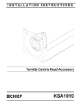
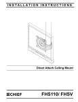
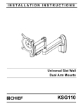
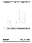
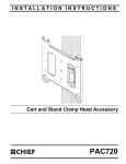
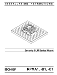
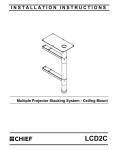
INSTALLATION INSTRUCTIONS
Centris Head Accessory
Model: FSA-1014
The FSA-1014 Centris Head Accessory is designed for
use with Chief F-Series Swing Arm mounts.
BEFORE YOU BEGIN
WARNING: It is the installer’s responsibility to make sure all components are properly assembled and installed
using the instructions provided. Failure to read, thoroughly understand, and follow all instructions can result in
serious personal injury, damage to equipment, or voiding of factory warranty.
•
If you have any questions about this these instructions or your specific installation, contact Chief Manufacturing
at 1-800-582-6480 or 952-894-6280.
CSAV, Inc., and its affiliated corporations and subsidiaries (collectively, "CSAV"), intend to make this manual accurate and complete. However,
CSAV makes no claim that the information contained herein covers all details, conditions or variations, nor does it provide for every possible
contingency in connection with the installation or use of this product. The information contained in this document is subject to change without notice
or obligation of any kind. CSAV makes no representation of warranty, expressed or implied, regarding the information contained herein. CSAV
assumes no responsibility for accuracy, completeness or sufficiency of the information contained in this document.
CHIEF MANUFACTURING INC.
1-800-582-6480 952-894-6280 FAX 952-894-6918
8401 EAGLE CREEK PARKWAY, STE 700
SAVAGE, MINNESOTA 55378 USA
8804-000294
2006 Chief Manufacturing
www.chiefmfg.com
06/06
Model: FSA-1014
Installation Instructions
IMPORTANT WARNINGS AND CAUTIONS!
WARNING: A WARNING alerts you to the possibility of serious injury or death if you do not follow the instructions.
CAUTION: A CAUTION alerts you to the possibility of damage or destruction of equipment if you do not follow the
corresponding instructions.
WARNING: Exceeding the weight capacity can result in serious personal injury or damage to equipment! Read and
understand the installation instructions provided with the mount this accessory is being installed on, and thoroughly
understand the mounts weight limits.
2
Installation Instructions
Model: FSA-1014
TOOLS REQUIRED FOR INSTALLATION
•
•
Phillips Screwdriver
5/32" Hex Wrench
Other tools may be required depending on your method
of installation.
PARTS
After unpacking carton, inspect and verify contents
(See Table 1 and Figure 1). If any listed parts are
missing or damaged, contact Chief Customer Service at
1-800-582-6480.
Table 1: Parts
Item
Description
Qty
10
Centris Head Assembly
1
20
WASHER, Nylon
1
30
PIN, Pivot
1
40
SCREW, Button Head Cap, 5/16-18 x 4"
1
50*
SCREW, Button Head Cap, 5/16-18 x 4 1/2"
1
60
Nut, NYLOCK, 5/15-18
1
70
SPACER
2
80
WASHER, UHMW
1
90
SCREW, Phillips head machine, M4 x 12mm
4
100
SCREW, Phillips head machine, M4 x 20mm
4
110
SCREW, Phillips head machine, M4 x 30mm
4
120
SPACER, Nylon, 1/2 x .194 x 3/8"
4
130
SPACER, Nylon, 1/2 x .194 x 3/4"
4
* Used when installing onan adjustable arm mount.
10
50
40
30
20
70
80
60
90
110
130
120
100
Figure 1: PARTS
3
Model: FSA-1014
Installation Instructions
MOUNT INSTALLATION
4. Install threaded end of BHCS (40 or 50) through
Centris Head (10), pivot pin (30) Nylon Washer (20)
and through mount end.
Existing Mount Preparation
If the FSA-1014 Accessory is being installed on an
existing Chief F- Series static or height adjustable mount
the existing mount needs to be modified before
installation.
5. Slide Nylock nut (60) up into bottom of mount end.
6. Hold Nylock nut (60) in position and thread Nylock nut
(60) onto bottom of BHCS (40 or 50). (See Figure 3)
To prepare the existing mount:
1. Disconnect all cables and wiring from display.
1. Remove display, if present, from existing mount
following the instructions supplied with mount.
40 or 50
2. Loosen button head cap screw securing display end
of mount to mount arm using a 5/32" hex key.
70
3. Uninstall button head cap screw, one nylon washer,
and two flat washers from swing arm and set aside for
reuse. (See Figure 2)
80
4. Remove large nylon washer, pivot pin, and Nylock nut
from existing mount base and set aside for reuse.
(See Figure 2)
70
button head cap screw
Flat Washer
Swing Arm or other
mount end.
Nylon Washer
30
Flat Washer
10
Large Nylon Washer
20
Pivot Pin
Existing Mount Base
Nylock Nut
Figure 2: Prepare Existing Mount
Existing Mount
Centris Cup Installation
To install the FSA-1014:
1. Place pivot pin (30) into mount end. (see Figure 4)
60
2. Place nylon washer (20) on top of mount end.
3. Assemble two spacers (70) and one UHMW washer
to BHCS (40 or 50).
Figure 3: Centris Head Installation
4
Installation Instructions
Model: FSA-1014
DISPLAY INSTALLATION
3. Select proper length spacer and screw from table
below:
SINGLE DISPLAY AND KCY-210/-220
The mounting holes on the back of your display will either
be flush with the back surface, or recessed into the back
surface. Refer to the appropriate installation procedure
below.
NOTE: All spacers used should be the same length. If
the recess depths result in multiple spacer
lengths, then select the longer spacer.
IF recess DEPTH is: THEN use spacer:
FLUSH MOUNTING HOLES
CAUTION: Using screws of improper size may
damage your display! Proper screws will easily and
completely thread into display mounting holes.
CAUTION: Inadequate thread engagement in display
may cause display to fall! Back out screws ONLY as
necessary to allow installation of Centris bracket!
1. Using Phillips screwdriver, carefully install two screws
(90) into the upper mounting holes on the display.
Thread screws completely into display, then back out
3 complete turns.
2. Pick up and align display so that screws (90) (installed
on the back of the display in the previous step) fit into
the mounting holes on the Centris bracket (10); rotate
the bracket as required (See Figure 4). Lower the
display firmly into place.
AND screw:
3/8" or less
120 (3/8" long)
100 (M4 x 20mm)
More than 3/8" up to
and including 3/4"
130 (3/4" long)
110 (M4 x 30mm)
4. Place the four selected spacers (120 or 130) over
each of the mount holes on the back of the display.
5. Pick up and orient the mount such that the mounting
holes in the Centris bracket (10) are aligned with the
holes in the spacers (120 or 130); rotate the bracket
as required (See Figure 5).
10
Mount
90, 100, or 110
(4 places)
120 or 130
(4 places)
Mount
Figure 5: Single Display - Recessed Mount
90
(2 places)
10
Figure 4: Single Display - Flush Mount
3. Using Phillips screwdriver, install two remaining
screws (90) through the lower mounting holes in
Centris bracket into the display.
CAUTION: Using screws of improper size may
damage your display! Proper screws will easily and
completely thread into display mounting holes.
6. Using Phillips screwdriver, install four selected
screws (100 or 110) through the mounting holes in
Centris bracket (10), through the spacers (120 or
130), into the display (See Figure 5). Tighten all four
screws. Do not overtighten!
4. Tighten all four screws (90). Do not overtighten!
RECESSED MOUNTING HOLES
1. Carefully place display face down on protective
surface.
2. Determine depth of recessed mounting holes relative
to back surface of display (against which Centris head
will contact).
5
Model: FSA-1014
6
Installation Instructions