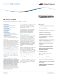
1
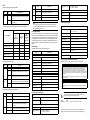
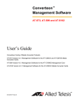
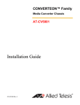
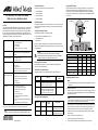
Setting the DIP Switches This product is supported in all four Converteon enclosures: The line card has DIP switches for setting the operating mode. You can also set the operating mode with the optional AT-CV5M02 Management Card. To use the DIP switches, refer to the figure and table. For background information on the operating modes, refer to the Converteon AT-S73, AT-S99, and AT-S102 Management Software User’s Guide. AT-CV5000 Chassis AT-CV1203 Chassis AT-CV1200 Chassis AT-CV1000 Chassis 100Base-FX Port Fiber Optic Port Connectors Operating Modes IEEE 802.3u Auto-Negotiation Half- or full-duplex mode Auto-MDI/MDI-X RJ-45 connector IEEE 802.3x flow control at 10 or 100 Mbps AT-CM301 - duplex ST AT-CM302 - duplex SC Link Test MissingLink™ Smart MissingLink Other Features The following items should be in the shipping container: One AT-CM301 or AT-CM302 Media Converter This Installation Guide Warranty card Loopback tests* Remote Converteon line card management* Remote management software downloads* Dying gasp** Variable requests* Jumbo frames up to 10,240 bytes Ingress and egress packet rate limiting* Operating mode and port status LEDs Low power mode Cyclical redundancy check Suitable for managed and unmanaged network environments Management available with the AT-CV5M02 Management Card AT-S102 Management Software (preinstalled) SW1 4 1 4 3 2 1 1448 Caution The media converter line card is sensitive to and can be damaged by electrostatic discharge. Wear a grounding device and observe electrostatic discharge precautions when installing the card in the chassis. Operating Mode Switch 4 Switch 3 Switch 2 Switch 1 Link Test (default setting) Off Off Off Off MissingLink Off Off Off On Before installing the media converter, review the safety precautions detailed in the Converteon chassis’ Installation Guide. Smart MissingLink Off Off On Off Link Test with OAM Off On Off Off Twisted Pair Cable Specifications MissingLink with OAM Off On Off On Smart MissingLink with OAM Off On On Off Reviewing Safety Precautions The cable specifications for the 10/100Base-TX twisted pair port are listed here. Speed Maximum Operating Distance Cable Type 10 Mbps Standard TIA/EIA 568-B-compliant Category 3 or better shielded or unshielded cabling with 100 ohm impedance and a frequency of 16 MHz. 100 m (328 ft) 100 Mbps Standard TIA/EIA 568-A-compliant Category 5 or TIA/EIA 568-B-compliant Enhanced Category 5 (Cat 5e) shielded or unshielded cabling with 100 ohm impedance and a frequency of 100 MHz. 100 m (328 ft) Installing the Media Converter Note The media converter supports hot swapping and can be installed while the chassis is powered on. To install the media converter: 1. Fiber Optic Cable Specifications Line Card Connector (* Requires the AT-CV5M02 Management Card.) (** Requires an AT-CV5M02 Management Card in the upstream AT-CV5000 Chassis.) Note These line cards cannot be managed with the AT-CV5M01 Management Card. *613-001068 RevA* On 1447 If any item is missing or damaged, contact your Allied Telesis sales representative for assistance. You should retain the original shipping material in case you need to return the unit to Allied Telesis. The operating modes can be activated with or without support for Operations, Administration, and Maintenance. Operations, Administration, and Maintenance (OAM) Features Off Verifying the Package Contents Supports distances up to 2 kilometers (1.24 miles) using 50/125 µm or 62.5/125 µm (core/cladding) multimode fiber optic cable. 1 ON 10/100Base-TX Twisted Pair Port For background information on the Converteon product, refer to the Converteon AT-S73, AT-S99, and AT-S102 Management Software User’s Guide, available from the Allied Telesis web site. ON The AT-CM301 and AT-CM302 Media Converters are members of the Converteon family of media converter products. They provide a simple and reliable way to connect Fast Ethernet networks across distances of up to 2 kilometers (1.24 miles) using multimode fiber optic cable. The products feature a 10/100Base-TX port and a 100Base-FX port. The two cards support all of the same features, but they have different connectors on the 100Base-FX fiber optic ports. The features are listed here. SW1 4 1 2 3 4 Overview DIP Switch 1 DIP Switch 4 Related Documents OFF OFF AT-CM301 and AT-CM302 Fast Ethernet Media Converters Installation Guide Converteon Enclosures Maximum Distance Note Retain the slot cover and reinstall it if you ever remove the card. An open slot allows dust to enter the unit and reduces proper airflow in the chassis. Fiber Optic Cable AT-CM301 Duplex ST 2 km (1.24 mi.) 50/125 µm or 62.5/125 µm (core/ cladding) multimode fiber optic cable AT-CM302 Duplex SC 2 km (1.24 mi.) 50/125 µm or 62.5/125 µm (core/ cladding) multimode fiber optic cable 613-001068 Rev. A 1 Remove the slot cover from one of the slots in the Converteon chassis by loosening the captive screw with a Phillips head screwdriver. The unit can be installed in any of the media converter slots. 2 2. Align the edges of the line card with the guides in the slot and carefully slide the card into the chassis until it is flush with the front of the chassis. Light pressure may be needed to seat the module on the connector on the backplane in the chassis. 3. Secure the line card in the chassis by tightening the captive-screw with a Phillips head screwdriver. 4. Remove the dust cover from the fiber optic port. 5. Connect the fiber optic cable to the fiber optic port. 6. Connect a twisted pair cable to the RJ-45 twisted pair port on the line card. 3 LEDs LED The RDY LED displays general status information. LED State RDY (Ready) Off Status/Operating Mode The line card is initializing the AT-S102 Management Software, which takes approximately one minute, or the card is not receiving power. Green The line card has initialized its management software and is ready to transfer network traffic. ML (Missing Link) Off The port is operating in half-duplex mode. Green The port is operating in full-duplex mode. Wavelength 1310 nm 100M Off The port is operating at 10 Mbps. Sensitivity -31 dBm max. Green The port is operating at 100 Mbps. Maximum Input Power -14 dBm min. Technical Specifications Off Off Off Link Test mode with OAM Off Off On Default Settings MissingLink mode Off On Off The default settings for the media converters are listed here. MissingLink mode with OAM Off On On Smart MissingLink mode On Off Off Smart MissingLink mode with OAM On Off On Feature LK (Link) AT (Activity) Default Setting 22 mm x 73 mm x 130 mm (.86 in. x 2.9 in. x 5.1 in.) Weight 113 grams (0.25 lb.) Operating Temperature 0° C to 40° C (32° F to 104° F) Storage Temperature -25° C to 70° C (-13° F to 158° F) Operating Relative Humidity 5% to 90% RH (non-condensing) Storage Relative Humidity 5% to 95% RH (non-condensing) Operating Altitude Range Up to 3,048 m (10,000 ft.) MTBF 1,500,000 hours Description Power Consumption Operating Mode Link Test Maximum Frame Size 10240 bytes Twisted Pair Port Auto-Negotiation with auto-MDI/MDI-X Ingress and Egress Filtering None Off The fiber optic port has not formed a link with the remote device. Low Power Mode Disabled Green The port has formed a link with the fiber optic port on the remote device. Operating Mode DIP Switches Enabled Blinking Green The media converter is operating in the Smart MissingLink mode and the twisted pair port has not formed a link with a network device. Off The port is not connected to a fiber optic cable, has not formed a link with the remote device, or is not sending or receiving network traffic. Blinking Green Dimensions (H x W x L) Electrical Ratings Basic Settings The 100Base-FX port has two LEDs. Color Physical and Environmental The recessed ECO Friendly button on the front panel of the line card is used to toggle the low power mode, which controls the LEDs. You can use the mode to turn off the LEDs to conserve power when you are not monitoring them. To toggle the LEDs on or off, press the recessed button with a pointed object, such as the end of a straightened paperclip. You can also toggle the low power mode with the AT-CV5M02 Management Card. The low power mode does not affect the network operations of the line card or control the RDY LED. Link Test mode LED Receiver ECO Friendly Button OAM (Operations, Administration and Maintenance) Admin State Enabled Mode Passive Electrical, Safety, and Emissions Statements U.S. Federal Communications Commission RADIATED ENERGY Note: This equipment has been tested and found to comply with the limits for a Class A digital device pursuant to Part 15 of FCC Rules. These limits are designed to provide reasonable protection against harmful interference when the equipment is operated in a commercial environment. This equipment generates, uses, and can radiate radio frequency energy and, if not installed and used in accordance with this instruction manual, may cause harmful interference to radio communications. Operation of this equipment in a residential area is likely to cause harmful interference in which case the user will be required to correct the interference at his own expense. Note: Modifications or changes not expressly approved of by the manufacturer or the FCC, can void your right to operate this equipment. Industry Canada Maximum OAMPDU Size 1518 bytes This Class A digital apparatus meets all requirements of the Canadian Interference-Causing Equipment Regulations. Loopback Support Enabled Variable Retrieval Support Enabled Cet appareil numérique de la classe A respecte toutes les exigences du Règlement sur le matériel brouilleur du Canada. Emission The 10/100Base-TX twisted pair port has four LEDs. Fiber Optic Port Specifications LED LK (Link) Color Off The port has not formed a link with a network device. Green The port has formed a link with a network device. Flashing Green AT (Activity) Description Off The port is not receiving or transmitting network packets. Blinking Green The port is receiving or transmitting network packets. Maximum Distance 2 km (1.24 miles) Fiber Optic Cable 50/125 µm or 62.5/125 µm (core/cladding) multimode fiber optic cable FCC Class A, EN55022 Class A, VCCI Class A, C-TICK, CE Warning In a domestic environment this product may cause radio interference in which case the user may be required to take adequate measures. General The media converter is operating in the Smart MissingLink mode and the fiber optic port has not formed a link with a network device. 8.5 Watts maximum Standards: This product meets the following standards when installed in compliant host equipment. OAM Settings The fiber optic port is receiving or transmitting network packets. BOL: -19 dBm min.; -14 dBm max. EOL: -20 dBm min.; -14 dBm max. FD (Full duplex) For more information on the Link LEDs, refer to the explanation of the media converter operating modes in the Converteon AT-S73, AT-S99, and AT-S102 Management Software User’s Guide. LEDs SML (Smart MissingLink) Output Optical Power - 62/ 125 µm Description Note The operating mode of the line card is displayed by the SML, ML and OAM LEDs. Operating Mode Color Immunity EN55024 Electrical Safety UL60950-1 (cULus), EN60950-1 (TUV), CAN/CSA C22.2 No. 60950-1 Transmitter 4 Wavelength 1310 nm Output Optical Power - 50/ 125 µm BOL: -22.5 dBm min.; -14 dBm max. EOL: -23.5 dBm min.; -14 dBm max. Copyright © 2008 Allied Telesis, Inc. All rights reserved. No part of this publication may be reproduced without prior written permission from Allied Telesis, Inc. www.alliedtelesis.com. 5 6