1
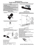
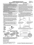
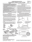
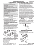
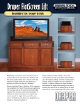
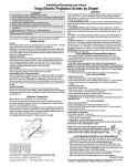
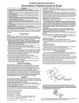
Installation/Operating Instructions
Access/Series M Projection Screen by Draper
Caution
➀ Read instructions through completely before proceeding.
➁ Follow instructions carefully. Installation contrary to instructions
invalidates warranty.
➂ Entire bottom of screen case should be unobstructed to permit access
to bottom panel for servicing.
➃ Screen should be installed level (using a carpenter’s level).
➄ Nothing should be fastened to screen dowel or viewing surface.
NOTE: Screen has been thoroughly inspected and tested at factory and
found to be operating properly prior to shipment.
With bottom access panel
angled up approx. 20 degrees,
engage hook on the panel
with lip of the housing
Using the hook and lip as a pivot,
pull the panel downward until the
engagement brackets click into
place with the ball detent
on each endcap
Hanging Screen
When locating viewing surface and checking clearance for screen operation,
remember surface is centered in the length of the case. Regardless of
mounting method used, the following points apply:
➀ Mounting brackets are shipped attached to the case. Engage each bracket
with top of housing as shown below and tighten set screws. A bracket
should be within 18" of each end of screen case. Brackets can be removed
and case mounted with lag screws through top of case (holes drilled on
site).
➁ Screen should be positively and securely supported so that vibration or
even abusive pulling on viewing surface will not weaken installation.
➂ Installer must insure that fasteners used are of adequate strength and
suitable for the mounting surface chosen. Supporting hardware (chains,
cables, 3/8" rods, etc.) must be essentially vertical.
➃ Entire bottom of case must be readily accessible after installation is
complete.
➄ Front, back and top of case must be straight—not forced to warp or bow.
➅ If case is painted on location, removal of roller/fabric assembly is
recommended prior to painting. If not removed, slot on bottom of case
should be shielded to protect viewing surface from paint splatters or
overspray.
Engagement bracket
(one on each end of the
bottom access panel)
Remove bottom access panel by pushing up at each corner of panel adjacent
to slot in bottom of the housing.
With bottom access panel angled up approximately at 20° it can be lifted off of
the lip of the housing and then lowered out of the housing completely.
Bottom flange of Access housing
Bottom access panel pushup
points for panel removal
Caution: Beware of pinch
points at ends of closure
Typical
Installation
Access case as seen from below
Spring Roller/Fabric Installation
Slots along
top of case
permit
brackets to
be set at an
angle
Alternate
Installation
(additional
set of
brackets
required
but not
included)
Bottom Access Panel Installation/Removal
Bottom access panel hooks over the lower inside edge of the screen housing
and then is pivoted downward until the engagement brackets on each end of
the bottom panel click into place with the ball detents on each endcap. Make
sure bottom access panel clicks in place at each end of its length.
®
The bottom access panel must be removed first.
The spear end mounting bracket has rectangular openings for accepting roller
spear. Back out the four set screws in bracket until they are flush with top side
of bracket.
To engage the spear end bracket flange above the two channels in the top of
the screen housing, rotate the bracket approximately 45° counterclockwise
to allow the top surface of the motor bracket to rest flat against the top
inside of the housing. Rotating the bracket clockwise until it is engaged with
the channels, slide it along the length of the housing toward the left end of
housing, leaving approximately 3/4" clearance between bracket and endcap.
Tighten the four set screws on the bracket flange using 1/8" hex key.
Engage the idler end bracket (nylon bushing) in the same manner as the
spear end bracket and slide it toward the opposite end of the screen housing.
Do not tighten the set screws on this bracket until the roller/fabric assembly is
installed.
Locate the roller/fabric assembly and remove the retaining clip and flat washer
from the idler end pin, and remove retaining clip from the spear. Remove
brackets from roller.
NOTE: This may require two people to perform safely. Raise the roller/
fabric assembly up into the screen housing and engage the spear of the roller
completely into the spear mounting bracket.
If roller is 13/4" diameter, there will be an arrow imprinted on the spring end
of the roller. This arrow must be pointing UP, and you must use the slot
closest to the edge of the bracket.
If roller is 21/4" or 3" diameter, there will be a notch cut out on the spring
end of the roller. This notch must be pointing DOWN, and you must use the
appropriate slot.
(Continued on page 2)
Copyright © 2009 Draper Inc. Form AccessM_Inst09
Printed in U.S.A.
If you encounter any difficulties installing or servicing your Access/Series M screen, call
your dealer or Draper, Inc., in Spiceland, Indiana, (765) 987-7999 or fax (765) 987-7142.
Page 2 of 2
Access/Series M by Draper
(Continued from Page 1)
Install the retaining clip on the spear, locking spear and bracket together.
While supporting the idler end of the roller, slide the idler end mounting
bracket toward the roller. Insert the roller pin into the nylon bushing on the
idler end mounting bracket.
The roller idler pin needs to go through the idler bracket far enough to allow
the washer and retaining clip to be reinstalled on the pin. Failure to replace
the washer and retaining clip as shown could result in the separation of the
roller from the brackets.
Securely tighten the four set screws on the idler end mounting bracket.
Reinstall the bottom access panel as previously described.
Roller pin
Retaining clip
Washer
Nylon bushing
Roller mtg. brkt.
Retaining
clip
Roller
Spring Roller/Fabric Removal
Standard Roller
Reverse the instructions above “Spring Roller/Fabric Installation” for removal
of the unit.
AutoReturn Roller
Roller Hole
Dia. Position
1¾"
A
2¼"
B
3"
C
Operating Instructions—Standard
To lower picture surface, pull screen down. Hesitate—then allow screen to
retract very slowly until it locks in place.
To raise picture surface, pull screen down and, while holding, allow for slow
retraction into the case to reduce risk of injury from falling screen.
B
B
C
A
A
Operating Instructions—AutoReturn
To lower picture surface, pull screen down. Hesitate—then allow screen to
retract very slowly until it locks in place.
To raise picture surface, pull screen down gently until it stops, then release.
water. Sponge the surface, rinse with clear water and blot dry. Do not use
cleaning solvents or abrasives.
Glass Beaded
Viewing Surface Care & Maintenance
Matt White & High Contrast Grey
Clean surface with a solution of mild dishwashing liquid diluted with warm
Clean with a very soft brush or cloth and carefully dust the surface. DO
NOT USE SOAP, WATER, SOLVENTS OR ABRASIVES. These substances
will damage a glass beaded viewing surface.
Case Dimensions
Mounting hardware supplied by others
Mounting brackets slide
left and right as needed.
9"
1"
11
/16"
7"
5
6 /8"
11
/16"
65/8"
21/8"
slot
3"
8"
Engagement bracket (one on each end
of the bottom access panel) clicks into
place with the ball detent on each endcap.
15/32"
21/8"
423/32"
Mounting Bracket Dimensions
3
/ 8"
13/8"
11/2"
1
/2"
R1/4"
3
5
/16" 3
/16"
/16"
1
/ 8"
11/8"
1
/4"
R1/8"
5
41/2"
/16"
11/4"
413/16"
3
7 /4"
9"
www.draperinc.com
(765) 987-7999
1
/4"