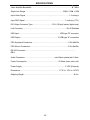
1
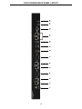
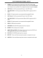
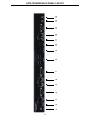
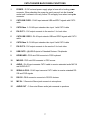
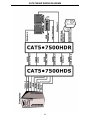
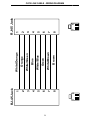
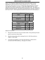
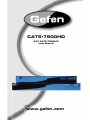
CAT5•7500HD
EXT-CAT5-7500HD
User Manual
www.gefen.com
ASKING FOR ASSISTANCE
Technical Support:
Telephone
(818) 772-9100
(800) 545-6900
Fax
(818) 772-9120
Technical Support Hours:
8:00 AM to 5:00 PM Monday thru Friday Pacific Time
Write To:
Gefen, LLC
c/o Customer Service
20600 Nordhoff St.
Chatsworth, CA 91311
[email protected]
www.gefen.com
Notice
Gefen, LLC reserves the right to make changes in the hardware, packaging and any
accompanying documentation without prior written notice.
All trademarks are the property of their respective owners.
© 2010 Gefen, LLC, All Rights Reserved
Rev A5
TABLE OF CONTENTS
1
Introduction and Operation Notes
2
How it Works
3
CAT5•7500HD Front Panel Descriptions
4
CAT5•7500HDS Back Panel Layout
5
CAT5•7500HDS Back Panel Functions
6
CAT5•7500HDR Back Panel Layout
7
CAT5•7500HDR Back Panel Functions
8
CAT5•7500HD - Wiring Diagram
9
CAT5 Link Cable Wiring Diagram
10
Service Switch Usage Guide
11
Frequently Asked Questions
12
Terminology
13
System Specifications
14
Warranty
INTRODUCTION
Thank you for purchasing the new ex•tend•it CAT5•7500HD series by Gefen, Inc.
cc.
di iin,
The CAT5•7500HD by Gefen allows users the benefits of extending USB, audio
audio out, PS/2, RS-232, and video signals beyond the desktop. In a growing number
of applications, broadcast stations and production facilities there is a need to locate a
computer remotely, from the keyboard, mouse, and video monitor. A CPU may need to be
shared between several users or moved to another room because of annoying fan noise.
The CAT5•7500HD series can be used to extend computers with noisy fans, printers, hard
drives, scanners, cameras, keyboards, mouse, and any other USB-type peripherals. The
CAT5•7500HD has the potential to cover the distance of 200 feet over industry standard
Category 5 (CAT-5) cables. One can connect additional CAT5•7500HD series to the
same computer, allowing access to the same computer from other locations up to 200
feet apart.
Lengths and Distances Supported:
Up to 200 Feet....................................................................................1280x1024 @ 60Hz
Up to 150 Feet....................................................................................1920x1200 @ 60Hz
OPERATION NOTES
READ THESE NOTES BEFORE INSTALLING
OR OPERATING THE CAT5•7500HD SYSTEM
• Industry standard Category-5 (CAT-5) cables are used to operate CAT5•7500HD systems.
• The CAT5•7500HD units are housed in a metal box for better RF shielding.
1
HOW IT WORKS
CONTENTS
The CAT5•7500HD system consists of:
--- (1) CAT5•7500HDS (Sender unit)
--- (1) CAT5•7500HDR (Receiver unit)
--- (2) 5 VDC power supply
--- (2) DVI cables (6FT)
--- (1) USB cable (6FT)
--- (2) PS/2 cables (6FT)
--- (1) Audio cable (6FT)
--- (1) Rack ears
--- (1) User Manual
HOW IT WORKS
In its most basic application, the CAT5•7500HDS Sender unit resides next to the computer.
Supplied with the system, DVI cables, PS/2 keyboard, PS/2 mouse, audio, and USB cables,
they connect the computer to the CAT5•7500HDS Sender unit.
The CAT5•7500HDR Receiver unit is placed next to the monitors, keyboard, mouse, and
USB peripherals at the remote location. The monitor and keyboard are connected to the
CAT5•7500HDR, similar to the way they are connected to the back of the computer (PC
or Macintosh).
2
CAT5•7500HDS FRONT PANEL DESCRIPTIONS
1
Front Panel Function Descriptions
1
Power On Indication - Indicates that the unit is on and plugged in.
CAT5•7500HDR FRONT PANEL LAYOUT
1
Front Panel Function Descriptions
1
POWER ON INDICATOR - Indicates that the unit is on and plugged in.
3
1
2
3
4
5
6
7
8
9
10
11
12
13 14
CAT5•7500HDS BACK PANEL LAYOUT
4
CAT5•7500HDS BACK PANEL LAYOUT
1
POWER - 5V DC external power supply plugs in here with a locking power
er
e
connector. When attaching the power tip, gently screw it into the threaded
d socket
until it refuses to turn any further. Do not apply force when turning the connector.
nnector
2
CAT5 Video 1 - RJ-45 input extends DVI input 1 with CAT-5 cable
3
CAT5 USB / DDC1 - RJ-45 input extends USB and DDC1 signals with CAT-5
cable
4
DVI IN 1 - DVI Input connects to your computer with the supplied DVI cable
5
CAT5 Video 2 - RJ-45 input extends DVI input 2 with CAT-5 cable
6
CAT5 USB / DDC2 - RJ-45 input extends USB and DDC2 signals with CAT-5
cable
7
DVI IN 2 - DVI Input connects to your computer with the supplied DVI cable
8
USB IN - USB Input from computer
9
KEYBOARD - Mini-DIN PS/2 keyboard input from computer
10
MOUSE - PS2 mouse input from computer
11
AUDIO / PS2 and RS-232 - RJ-45 input extends audio as well as RS-232 and
PS2 signals with a set of two (2) CAT-5 cables here.
12
RS-232 IN - RS-232 DB9 serial input from computer
13
MIC OUT - 3.5mm mini-Stereo input jack connects to computers' mic input
14
AUDIO IN - 3.5mm mini-Stereo input jack connects to computers' audio output
5
1
2
3
4
5
6
7
8
9
10
11
12
13
14 15
CAT5•7500HDR BACK PANEL LAYOUT
6
CAT5•7500HDR BACK PANEL FUNCTIONS
1
POWER - 5V DC external power supply plugs in here with a locking power
wer
w
connector. When attaching the power tip, gently screw it into the threaded
ed
g the
th
socket until it refuses to turn any further. Do not apply force when turning
connector.
2
CAT5 USB / DDC1 - RJ-45 input extends USB and DDC1 signals with CAT-5
cable
3
CAT5 Video 1 - RJ-45 input extends video input 1 with CAT-5 cable
4
DVI OUT 1 - DVI output connects to the monitor 1 for local video
5
CAT5 USB / DDC2 - RJ-45 input extends USB and DDC2 signals with CAT-5
cable
6
CAT5 Video 2 - RJ-45 input extends video input 2 with CAT-5 cable
7
DVI OUT 2 - DVI output connects to the monitor 2 for local video
8
USB OUTS - (4) USB Outputs to Extended Devices / Peripherals
9
KEYBOARD - PS/2 mini-DIN connects to PS/2 keyboard
10
MOUSE - PS/2 mini-DIN connects to PS/2 mouse
11
AUDIO - RJ-45 input connects CAT-5 cable to receive extended audio MIC IN
and AUDIO OUT.
12
SERIAL & PS/2 - RJ-45 input connects CAT-5 cable to receive extended RS232 and PS/2 signals
13
RS-232 - DB-9 connector connects to RS-232 devices
14
MIC IN - 3.5mm mini-Stereo jack connects to microphone
15
AUDIO OUT - 3.5mm mini-Stereo audio jack connects to speakers
7
CAT5•7500HD WIRING DIAGRAM
8
9
1
8
8
7
6
5
4
3
2
1
RJ-45 Jack
Brown
White/Brown
Green
White/Blue
Blue
White/Green
Orange
White/Orange
8
7
6
5
4
3
2
1
1
8
RJ-45 Jack
CAT5 LINK CABLE - WIRING DIAGRAM
SERVICE SWITCH USAGE GUIDE
Gefen C
CAT5 HD products (Sender and Receiver) both contain a pair of service
switchess (also called dip switches) located underneath the unit. These service
switchess are used to select from sets of configurations that will equalize the signal to
best ma
mat
match the conditions in your setup. For the CAT5•7500HD, there are 1 set of
switches for each monitor under both the Sender and Receiver units. The switches are
hidden beneath black stickers. Each bank of dip switches have 4 switches. Switches 3
and 4 are not used. (*Note: Adjustments should be done with sources and display on.)
Sender Dip Switch Settings
Setting
Switch 1 Switch 2
No Boost
OFF
ON
Normal Boost (Default)
OFF
OFF
Strong Boost
ON
OFF
Undefined
ON
ON
Receiver Dip Switch Settings
Setting
Switch 1 Switch 2
No EQ (Default)
OFF
OFF
EQ Setting 2
ON
OFF
EQ Setting 3
OFF
ON
Maximum EQ
ON
ON
Adjustment Guidelines:
1)
Strong boost should not be used on stranded cables. Strong boosting will cause
pixels or no picture on these cables.
2)
Using the wrong settings will not damage the units; it will either produce no
image or a noisy image.
3)
To eliminate the possibility of cross talk and interference, cables must be
terminated with 568B scheduling. (See page 9 for details)
10
FREQUENTLY ASKED QUESTIONS
What kind of CAT-5e cable should I be using?
Solid core CAT-5e cable rated at 350 Mhz and terminated in 568a or 568b is the
minimum requirement. For resolutions greater than 1280x1024 or 1080i, Gefen
recommends solid CAT-6 cables.
I’m getting no video on the screens, what can I check?
First thing to check is make sure that the video CAT5 is linked to the other video CAT5 port
and the same with the DDC ports. Test to make sure the units are working with short CAT-5e
cables 15-20 feet. You can also make sure you have the correct boost setting configured
(please refer to page 10).
I’m getting no video on the screens using ADC to DVI adapters, what is wrong?
ADC to DVI adapters remove the necessary 5V line that the extenders require on the input
to operate. To enable the 5V you will need to open up the Sender unit. Next to each DVI
input connector will be a jumper that needs to be shorted to enable 5V to the input. This
should only be enabled when using a ADC to DVI Adapter otherwise damage to your video
card may result.
How can I fix a flickering picture?
Flickering or a blinking image is the result of a loss of sync between the display and
the source. Try lowering the resolution, if this helps, the CAT-5 cables you are using
are unable to handle the bandwidth of the higher resolution and thus you are losing
sync. Try a shielded CAT-6 cable on the video line to reduce interference, which can
be caused by EMI. A shielded CAT-6 with metal RJ-45 connectors with the drain wire
soldered to the connectors will resolve an EMI issue. You can also try adjusting the
service switches. Page 10 contains a guide to setting the service switches.
Why is there a green or pink tint to my picture?
A tint of green or pink in the picture is a result of incorrect colorspace being transmitted.
This can be resolved by recycling power on your devices including the extender. If this
does not help, the DDC data containing the colorspace is not being transmitted correctly
due to loss in the CAT5 cable, try replacing the DDC cable.
Why is the USB dropping out every so often?
Drop outs occur on occasion but if it is happening quite often, then interference along the
DDC line that is also transmitting USB is causing the problem. Try using a shielded CAT5e cable on this line instead.
I can’t seem to get my RS-232 devices to detect and connect, what’s wrong?
The CAT5-7500HD system only extends the Tx and Rx lines of RS-232. If you need full
RS-232 extension of every line, you will need the standalone RS-232 Extender units.
Can I run the CAT-5 cable through a patch bay or punchdown block?
No, the signal will not transmit reliably.
11
TERMINOLOGY
CAT-5
Category 5 cable, commonly known as Cat 5, is an unshielded twisted pair type cable
designed for high signal integrity. The actual standard defi nes specific electrical
properties of the wire, but it is most commonly known as being rated for its Ethernet
capability of 100 Mbit/s. Its specific standard designation is EIA/TIA-568. Cat 5 cable
typically has three twists per inch of each twisted pair of 24 gauge copper wires within
the cable.
CAT-5e
Similar to Cat 5 cable, but is enhanced to support speeds of up to 1000 megabits per
second.
DDC
Short form for Display Data Channel, a VESA standard for communication between
a monitor and a video adapter. Using DDC, a monitor can inform the video card about
its properties, such as maximum resolution and color depth. The video card can then
use this information to ensure that the user is presented with valid options for confi
guring the display.
DDWG
Digital Display Working Group DDWG are the creators of the DVI specification.
DVI
Digital Visual Interface. Connection standard developed by Intel for connecting
computers to digital monitors such as fl at panels and DLP projectors. A consumer
electronics version, not necessarily compatible with the PC version, is used as a
connection standard for HDTV tuners and displays. Transmits an uncompressed
digital signal to the display. The latter version uses HDCP copy protection to prevent
unauthorized copying of source material.
USB
Universal Serial Bus. An external peripheral interface standard for communication
between a computer and external peripherals over a cable using bi-serial transmission.
VESA
Video Electronic Standards Association, a consortium of manufacturers formed to
establish and maintain industry wide standards for video cards and monitors. VESA was
instrumental in the introduction of the Super VGA and Extended VGA video graphics
standards with a refresh rate of 70 Hz, minimizing fl icker and helping to reduce user
eyestrain and fatigue.
PS/2
A port type developed by IBM for the purpose of connecting a keyboard or mouse to a
PC. The PS/2 port has a mini-DIN plug connector containing 6 pins. PS/2 ports are used
so that the serial port can be used by another device. The PS/2 port is often called the
mouse port.
12
SPECIFICATIONS
Video Amplifier Bandwidth ................................................................................ 165
65 MHz
6
Single Link Range ........................................................................... 1080p / 1920
0 x 1200
Input Video Signal ........................................................................................ 1.2 volts p-p
Input DDC Signal .................................................................................. 5 volts p-p (TTL)
DVI Output Connector Type ........................................DVI-I (29 pin) female (digital only)
Link Connector ........................................................................................ RJ-45 Shielded
USB Input .................................................................................. USB type "B" connector
USB Output ........................................................................... 2 USB type "A" connectors
PS/2 Keyboard Connectors ........................................................................ 6 Pin MiniDin
PS/2 Mouse Connectors ............................................................................ 6 Pin MiniDin
RS-232 Connector ....................................................................................................
DB-9
Audio Connection ........................................................... mini-Stereo phone jack 3.5mm
Power Consumption ............................................................... 20 Watts (max. each unit)
Power Supply ....................................................................................... 5 VDC (External)
Dimensions .............................................................................. 17”W x 1.75”H x 4.375”D
Shipping Weight ......................................................................................................8 Lbs
13
WARRANTY
Gefen warrants the equipment it manufactures to be free from defects in material
and workmanship.
If equipment fails because of such defects and Gefen is notified within two (2)
years from the date of shipment, Gefen will, at its option, repair or replace the
equipment, provided that the equipment has not been subjected to mechanical,
electrical, or other abuse or modifications. Equipment that fails under conditions
other than those covered will be repaired at the current price of parts and labor in
effect at the time of repair. Such repairs are warranted for ninety (90) days from
the day of reshipment to the Buyer.
This warranty is in lieu of all other warranties expressed or implied, including
without limitation, any implied warranty or merchantability or fitness for any
particular purpose, all of which are expressly disclaimed.
1.
Proof of sale may be required in order to claim warranty.
2.
Customers outside the US are responsible for shipping charges to and from
Gefen.
3.
Copper cables are limited to a 30 day warranty and cables must be in their
original condition.
The information in this manual has been carefully checked and is believed to
be accurate. However, Gefen assumes no responsibility for any inaccuracies
that may be contained in this manual. In no event will Gefen be liable for
direct, indirect, special, incidental, or consequential damages resulting from
any defect or omission in this manual, even if advised of the possibility of such
damages. The technical information contained herein regarding the features and
specifications is subject to change without notice.
For the latest warranty coverage information, please visit Gefen’s Warranty web
page at http://www.gefen.com/kvm/aboutus/warranty.jsp
PRODUCT REGISTRATION
Please register your product online by visiting Gefen’s web site at
http://www.gefen.com/kvm/Registry/Registration.jsp
14
*ma-cat5-7500hd*
Rev A5
20600 Nordhoff St - Chatsworth, CA 91311
1-800-545-6900
818-772-9100
www.gefen.com
Pb
fax: 818-772-9120
[email protected]