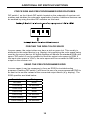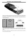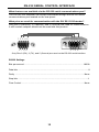
1
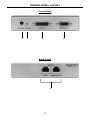
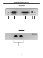
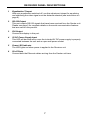
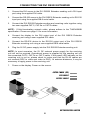
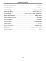
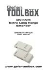
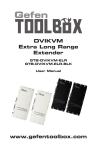
®
DVI RS232
Extender
EXT-DVIRS232-CAT5N
User Manual
www.gefen.com
ASKING FOR ASSISTANCE
Technical Support:
Telephone
Fax
(818) 772-9100
(800) 545-6900
(818) 772-9120
Technical Support Hours:
8:00 AM to 5:00 PM Monday thru Friday PST.
Write To:
Gefen LLC
c/o Customer Service
20600 Nordhoff St
Chatsworth, CA 91311
www.gefen.com
[email protected]
Notice
Gefen LLC reserves the right to make changes in the hardware, packaging and
any accompanying documentation without prior written notice.
DVI RS232 Extender is a trademark of Gefen LLC
© 2010 Gefen LLC, All Rights Reserved
All trademarks are the property of their respective owners
Rev A3
CONTENTS
1
Introduction
2
Features
3
Operation Notes
4
Sender Panel Layout
5
Sender Panel Descriptions
6
Receiver Panel Layout
7
Receiver Panel Descriptions
8
Connecting The DVI RS232 Extender
9
How to Equalize The Video Signal
10
Additional DIP Switch Functions
11
Network Cable Wiring Diagram
12
RS-232 Serial Control Interface
13
Specifications
14
Warranty
INTRODUCTION
Congratulations on your purchase of the DVI RS232 Extender. Your complete
satisfaction is very important to us.
Gefen
Gefen is a unique product line catering to the growing needs for innovative home
theater solutions. We specialize in total integration for your home theater, while
also focusing on going above and beyond customer expectations to ensure you
get the most from your hardware. We invite you to explore our distinct product
line and hope you find your solutions. Don’t see what you are looking for here?
Please call us so we can better assist you with your particular needs.
The DVI RS232 Extender
Extending state-of-the-art digital video displays, computer monitors and touch
screens has never been easier. Distances up to 150 feet at 1080p resolution (300
feet at 1080i resolution) are guaranteed to perform beautifully, giving you a reliable
method of all-digital extension while streamlining your installation cabling needs.
How It Works
You simply connect the DVI RS232 Extender sender unit to your DVI and RS232 source using the supplied cables. Your RS-232 device and the DVI display
plugs into the DVI RS232 Extender’s receiver unit. Two CAT-5 cables connect the
sender and the receiver units to each other allowing for up to 300 feet of extension
(300 feet at 1080i resolution or 150 feet of extension at 1080p resolution).
1
FEATURES
Features
•
Supports resolutions up to 1080p, 2K, and 1920 x 1200
•
Sends video at distances of up to 300 feet (1080i) / 150 feet (1080p)
•
Small and compact
•
Improved compensation for cable skew
•
Audio and video are transmitted digitally over the CAT-5, CAT-5e or CAT-6
cable for zero signal loss
•
Eliminates equipment noise in the viewing environment
Package Includes
(1) DVI RS232 Extender Sender Unit
(1) DVI RS232 Extender Receiver Unit
(1) 6 Foot DVI Cable (M-M)
(1) 6 Foot RS-232 Cable (M-M)
(2) 5V DC Power Supply
(1) User’s Manual
2
OPERATION NOTES
READ THESE NOTES BEFORE INSTALLING OR
OPERATING THE DVI RS232 EXTENDER
•
Use two industry standard CAT-5, CAT-5e or CAT-6 cables to operate the DVI
RS232 Extender. Gefen recommends CAT-6 cabling for maximum performance.
•
For 1080i video, maximum extension is 300 feet (91 meters).
•
This product features the option to force the output color space to RGB and/
or use a pre-programmed EDID. These features can be used to resolve
specific user issues or for troubleshooting purposes (see page 10 for more
information).
3
SENDER PANEL LAYOUT
Front Panel
1
2
3
4
Back Panel
5
4
SENDER PANEL DESCRIPTIONS
1
5V DC Power Supply Input
Connect the 5V DC external power supply to this port.
2
Power LED Indicator
This LED will become active once the included 5V DC power supply is properly
connected between the unit and an open wall power socket.
3
DVI Input
Connect the DVI source into this port.
4
RS-232 Input
This port is used to extend the RS-232 signals. Please see page 5 for complete
details on the serial communication features that are used on this product.
5
RJ-45 Ports
Use these ports to connect the Ethernet cables connecting the Sender and
Receiver together and the other Ethernet channel used for the RS-232 backchannel.
5
RECEIVER PANEL LAYOUT
Front Panel
1
2
3
Back Panel
6
6
4
5
RECEIVER PANEL DESCRIPTIONS
1
Equalization Trimpot
With auto-equalization switched off, use this adjustment trimpot for equalizing
and stabilizing the video signal over the distance selected (see instructions on
page 9).
2
RS-232 Output
This port outputs RS-232 signals that have been received from the Sender unit.
Please see page 5 for complete details on the serial communication features
that are used on this product.
3
DVI Output
Connect the display to this port.
4
5V DC Power Supply Input
This LED will become active once the included 5V DC power supply is properly
connected between the unit and an open wall power socket.
5
Power LED Indicator
The LED lights red when power is applied to the Receiver unit.
6
RJ-45 Ports
Connect both the Ethernet cables arriving from the Sender unit here.
7
CONNECTING THE DVI RS232 EXTENDER
1.
Connect the DVI source to the DVI RS232 Extender sending unit’s DVI input
port using the supplied DVI cable.
2.
Connect the RS-232 source to the DVI RS232 Extender sending unit’s RS-232
input port using the supplied DB-9 serial cable.
3.
Connect the DVI RS232 Extender sending and receiving units together using
two user supplied CAT-5, CAT-5e or CAT-6 cables.
NOTE: If field terminating network cable, please adhere to the TIA/EIA568B
specification. Please see page 12 for more information.
4.
Connect the display to the DVI output port of the DVI RS232 Extender
receiving unit using a user supplied DVI cable.
5.
Connect the RS-232 device to the RS-232 output port of the DVI RS232
Extender receiving unit using a user supplied DB-9 serial cable.
6.
Plug the 5V DC power supply into the DVI RS232 Extender sending unit.
NOTE: In most scenarios, the 5V DC external power supply for the receiving
unit will not be required. Operational power is supplied by the sending unit via
the connected CAT-5, CAT-5e or CAT-6 cable. If the power LED indicator on the
receiving unit is not on, please check to make sure that the RJ-45 cables are
not crossed (DDC to video and video to DDC). At extreme distances, it may be
necessary to apply power to the receiving unit.
7.
Power on the display. Power on the source.
CAT5E CABLE (2X)
(Up to 300 ft)
DVI CABLE
RS232 CABLE
Computer
Receiver
Sender
Touch Screen
n Monitor
EXT-DVIRS232-CAT5N
8
HOW TO EQUALIZE THE VIDEO SIGNAL
The DVI RS232 Extender has built-in auto equalization that will automatically
tune out any unwanted video noise. This feature is reliable with premium cable
runs up to a maximum of 130 feet. If your cable run is beyond 130 feet, it may be
necessary to use manual equalization.
The sender and receiver units both have sets of DIP switches located on the
underside of their enclosure. Remove the silver metallic tape to expose these
DIP switches. By default, all DIP switches on the sending and receiving units
should be in the OFF position (Auto EQ On). To turn on manual equalization, set
DIP switch 1 on the receiver to the ON position then follow the instructions below
(see page 10 for additional DIP switch information).
1.
Insert a small flat head tool into the trimpot on the receiver unit.
2.
Turn the trimpot in a clockwise fashion until it comes to a stop. Do not force the
trimpot beyond this point. Doing so may break the trimpot.
3.
Slowly turn the trimpot counter-clockwise in millimeter increments until the
image stabilizes and all video noise disappears.
NOTE: If the following steps still do not produce any video, it may be necessary
to increase the boost from the sending unit. Use the chart below to increase the
boost by changing the sender DIP switches. Once a new boost setting is set,
repeat steps 1 through 3 from above.
Sender DIP Switch Settings
Setting
Switch 1
Switch 2
No Boost (Default)
OFF
OFF
Very Low Boost
ON
ON
Medium Boost
OFF
ON
High Boost
ON
OFF
Note: DIP Switches 3 and 4 have no function on this unit
Receiver DIP Switch Settings
Setting
Switch 1
Switch 2
Manual EQ
ON
N/A
Switch 3
N/A
Auto EQ (Default)
OFF
OFF
N/A
Force RGB on Output
N/A
ON
N/A
Pre-Programmed EDID
N/A
N/A
ON
Note: DIP Switch 4 has no function on this unit
9
ADDITIONAL DIP SWITCH FUNCTIONS
FORCE RGB AND PRE-PROGRAMMED EDID FEATURES
DIP switch 1 on the 4-bank DIP switch located on the underside of receiver unit
enables and disables the automatic equalization function. Additional features can
be enabled by using the other DIP switches on this bank.
FORCING THE RGB COLOR SPACE
In some cases, the output video may have a pink or green tint. This usually is
attributed to the output device (e.g. display) not supporting the color space being
used by the source device. All digital displays will handle the standard RGB color
space. DIP switch 2 can be enabled to force the output color space to RGB. If
the input color space is YCbCr, the color space will be converted to RBG prior to
output on the receiver unit.
USING THE PRE-PROGRAMMED EDID
In some cases it may be necessary to force an EDID for troubleshooting
purposes. Enabling DIP switch 3 will force the use of a pre-programmed EDID to
be sent to the source instead of the connected output device (e.g. display). The
EDID specifics are listed below.
Resolution
Timing
640x480
60Hz
720x480i/p
59.94/60Hz
720x576i/p
50Hz
1280x720p
50Hz
1280x720p
59.94/60Hz
1920x1080i/p
50Hz
1920x1080i/p
59.94/60Hz
10
NETWORK CABLE WIRING DIAGRAM
Gefen has specifically engineered their products to work with the TIA/EIA-568-B
specification. Please adhere to the table below when field terminating cable for
use with Gefen products. Failure to do so may produce unexpected results and
reduced performance.
Pin
Color
1
Orange / White
2
Orange
3
Green / White
4
Blue
5
Blue / White
6
Green
7
Brown / White
8
Brown
12345678
CAT-5, CAT-5e, and CAT-6 cabling comes in stranded and solid core types. Gefen
recommends using solid core cabling. CAT-6 cable is also recommended for best
results.
Each cable run must be one continuous run from one end to the other: No splices
or use of punch down blocks.
11
RS-232 SERIAL CONTROL INTERFACE
What features are available via the RS-232 serial communications port?
The DVI RS-232 Extender can accept commands through the RS-232 serial
communications port located on the rear panel.
What pins are used for communication with the DVI RS-232 Extender?
Only pins 2 (Receive), 3 (Transmit), and 5 (Ground) are used for communication.
A null-modem adapter should not be used with this product.
12345
12345
6789
6789
Only Pins 2 (RX), 3 (TX), and 5 (Ground) are used on the RS-232 serial interface
RS232 Settings
Bits per second ................................................................................................. 19200
Data bits .................................................................................................................... 8
Parity .................................................................................................................. None
Stop bits .....................................................................................................................1
Flow Control ....................................................................................................... None
12
SPECIFICATIONS
Video Amplifier Bandwidth ....................................................................... 165 MHz
Input Video Signal .............................................................................. 1.2 Volts p-p
Input DDC Signal ......................................................................... 5 Volts p-p (TTL)
Single Link Range ................................................................... 1080p/1920 x 1200
DVI Connector ............................................... DVI-I (29 Pin) Female (Digital Only)
RS232 Input Connector .................................................................... DB-9 Female
RS232 Output Connector ...................................................................... DB-9 Male
RS-232 Standard ..................................................................................... RS-232C
Link Connector .............................................................................. RJ-45 Shielded
Power Supply .............................................................................................. 5V DC
Power Consumption ....................................................................... 10 Watts (max)
Dimensions ........................................................................3.2” D x 4.6”W x 1.25”H
Shipping Weight ............................................................................................. 4 lbs.
13
WARRANTY
Gefen warrants the equipment it manufactures to be free from defects in material
and workmanship.
If equipment fails because of such defects and Gefen is notified within two (2)
years from the date of shipment, Gefen will, at its option, repair or replace the
equipment, provided that the equipment has not been subjected to mechanical,
electrical, or other abuse or modifications. Equipment that fails under conditions
other than those covered will be repaired at the current price of parts and labor in
effect at the time of repair. Such repairs are warranted for ninety (90) days from
the day of reshipment to the Buyer.
This warranty is in lieu of all other warranties expressed or implied, including
without limitation, any implied warranty or merchantability or fitness for any
particular purpose, all of which are expressly disclaimed.
1.
Proof of sale may be required in order to claim warranty.
2.
Customers outside the US are responsible for shipping charges to and from
Gefen.
3.
Copper cables are limited to a 30 day warranty and cables must be in their
original condition.
The information in this manual has been carefully checked and is believed to
be accurate. However, Gefen assumes no responsibility for any inaccuracies
that may be contained in this manual. In no event will Gefen be liable for
direct, indirect, special, incidental, or consequential damages resulting from
any defect or omission in this manual, even if advised of the possibility of such
damages. The technical information contained herein regarding the features and
specifications is subject to change without notice.
For the latest warranty coverage information, please visit Gefen’s Warranty web
page at http://www.gefen.com/kvm/aboutus/warranty.jsp
PRODUCT REGISTRATION
Please register your product online by visiting Gefen’s web site at
http://www.gefen.com/kvm/Registry/Registration.jsp
14