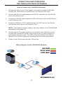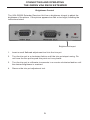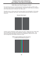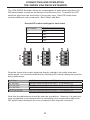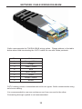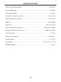
1
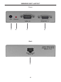
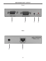
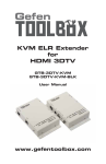
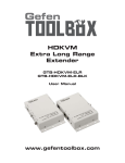
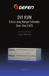
®
VGA RS232
Extender
EXT-VGARS232-141
User Manual
www.gefen.com
ASKING FOR ASSISTANCE
Technical Support:
Telephone
Fax
(818) 772-9100
(800) 545-6900
(818) 772-9120
Technical Support Hours:
8:00 AM to 5:00 PM Monday thru Friday, Pacific Time
Write To:
Gefen LLC
c/o Customer Service
20600 Nordhoff St
Chatsworth, CA 91311
www.gefen.com
[email protected]
Notice
Gefen LLC reserves the right to make changes in the hardware, packaging and
any accompanying documentation without prior written notice.
VGA RS232 Extender is a trademark of Gefen, LLC
© 2010 Gefen LLC, All Rights Reserved.
All trademarks are the property of their respective owners.
Rev A1
CONTENTS
1
Introduction
2
Operation Notes
3
Features
4
Sender Unit Layout
5
6
7
Sender Unit Descriptions
Receiver Unit Layout
Receiver Unit Descriptions
8
Connecting and Operating the VGA RS232 Extender
8
How to Connect the VGA RS232 Extender
8
Wiring Diagram
9
Brightness Control
10
Cable Skew / Color Divergence Control
12 RS-232 Serial Control
13 Network Cable Wiring Diagram
14 Wall Mounting Instructions
15 Specifications
16 Warranty
INTRODUCTION
Congratulations on your purchase of the Gefen VGA RS232 Extender. Your complete satisfaction is very important to us.
About Gefen
We specialize in total integration for your home theater, while also focusing on
going above and beyond customer expectations to ensure you get the most from
your hardware. We invite you to explore our distinct product line. Please visit
http://www.gefen.com for the latest offerings in High-Definition signal solutions
or call us between the hours of 8:00 am and 5:00 pm Monday-Friday, Pacific
Standard Time for assistance with your A/V needs. We’ll be happy to assist you.
The Gefen VGA RS232 Extender
The Gefen VGA RS232 extends any VGA source to a monitor or digital signage
application placed up to 330 feet (100 meters) using one CAT-5 cable. This
product also extends RS-232 using the same CAT-5 cable, allowing access to
control devices using RS-232.
How It Works
Place the Sender Unit next to the VGA source. Use the included VGA cable to
connect the source to the Sender Unit. Connect the Receiver Unit to the monitor
or digital signage display with a VGA cable (not supplied). Use one CAT-5 cable,
up to 330 feet (100 meters), to connect the Sender Unit to the Receiver Unit.
Connect an RS-232 serial cable from the RS-232 port on the Sender Unit to the
RS-232 control device. Connect the RS-232 port on the Receiver Unit to the RS232 device.
1
OPERATION NOTES
READ THESE NOTES BEFORE INSTALLING OR
OPERATING THE GEFEN VGA RS232 EXTENDER
•
CAT-5e cables should not exceed 330 feet (100 meters).
•
Unshielded (UTP) CAT-5e is recommended.
2
FEATURES
Features
•
Extends any VGA and RS-232 source up to 330 feet (100 meters)
•
Supports resolutions up to 1920x1200
•
All-digital signal transmission for zero signal loss
•
Metal enclosure improves RF shielding
Package Includes
(1) Gefen VGA RS232 Extender Sender Unit
(1) Gefen VGA RS232 Extender Receiver Unit
(1) 6 ft. VGA cable (M-F)
(1) 6 ft. serial cable (M-F)
(2) 5V DC Power Supplies
(1) Set of Wall Mounting Plates
(1) User Manual
3
SENDER UNIT LAYOUT
Front
1
2
3
4
Back
5
4
SENDER UNIT DESCRIPTIONS
1
5V DC Power Connector
Connect the included 5V DC power supply to this connector.
2
Power Indicator
This LED will turn bright red once the included 5V DC power supply has been
properly connected to the unit and the power supply has been connected to an
available electrical outlet.
3
Locking VGA Port
Connect a VGA source to this port.
4
RS-232 Port
Connect the RS-232 host device to this port.
5
CAT-5 Output Jack
Connects the Sender Unit to the Receiver Unit using a CAT-5 cable.
5
RECEIVER UNIT LAYOUT
Front
1
2
Back
5
5
6
3
4
RECEIVER UNIT DESCRIPTIONS
1
Locking VGA Port
Connect a VGA source device to this VGA port.
2
RS-232 Port
Connect the RS-232 device to this port.
3
Brightness Trimpot
Adjusts the brightness of the picture.
4
Power Indicator
This LED will turn bright red once the included 5V DC power supply has
been properly connected to the unit and the locking power supply has been
connected to an available electrical outlet.
5
5V DC Power Connector
Connect the included 5V DC power supply to this connector.
6
CAT-5 Input Jack
Connects the Sender Unit to the Receiver Unit using CAT-5 cabling.
7
CONNECTING AND OPERATING
THE GEFEN VGA RS232 EXTENDER
How to Connect the VGA RS232 Extender
1.
Connect the VGA source to the Sender Unit using the provided VGA cable.
Connect the VGA monitor to the Receiver Unit using a VGA cable.
2.
Connect the RS-232 cable between the RS-232 controller and the RS-232
port on the Sender Unit.
3.
Connect an RS-232 cable between the RS-232 device and the RS-232 port
on the Receiver Unit.
4.
Connect a CAT-5e or CAT-6 cable between the CAT-5 port on the Sender
Unit and the CAT-5 port on the Receiver Unit.
NOTE: If terminating network cables in the field, adhere to the TIA/EIA568B
specification (see page 12).
5.
Connect the 5V DC power supplies to the Sender Unit and Receiver Unit.
Connect the included AC power cords Plug the two (2) power supplies to
an available electrical outlet. The LED on both the Sender Unit and the
Receiver Unit will turn bright red, indicating that both units are powered.
6.
Power on the VGA monitor and the VGA source.
Wiring Diagram for the VGA RS232 Extender
VGA CABLE
RS232 CABLE
CAT5E CABLE
,
(Up to 330
ft)
Computer
Receiver
Sender
Digital Signage Display
EXT-VGARS232-141
8
CONNECTING AND OPERATING
THE GEFEN VGA RS232 EXTENDER
Brightness Control
The VGA RS232 Extender Receiver Unit has a brightness trimpot to adjust the
brightness of the picture. If the picture appears too dark or too bright, following the
instructions below.
Brightness trimpot
1.
Insert a small flathead adjustment tool into the trim pot.
2.
Turn the trim pot in a clockwise fashion until the trim pot stops turning. Do
not force the trim pot beyond this point as it may break.
3.
Turn the trim pot in millimeter increments in a counter-clockwise fashion until
the desired brightness is reached.
4.
Remove the trim pot adjustment tool.
9
CONNECTING AND OPERATING
THE GEFEN VGA RS232 EXTENDER
Cable Skew and Color Divergence Control
To reduce the amount of crosstalk between twisted pairs within a CAT-5 cable,
the rate of twist varies for each twisted pair. The rate of twist affects the length of
each twisted pair and is referred to as cable skew.
Normally, when a video signal with a single white line is displayed on the screen,
each color component (red, green, blue) combines with the other to create the
white line.
Normal video signal
However when extending a video signal over CAT-5, cable skew can cause each
color component to arrive at the destination (display) at different times. This
causes an undesirable effect known as color divergence, where one or more
color components are shifted to the left or right.
Video signal containing color divergence
(emphasized for illustrative purposes)
10
CONNECTING AND OPERATING
THE GEFEN VGA RS232 EXTENDER
The VGA RS232 Extender allows for compensation of cable skew using three (3)
DIP switch banks, located on the bottom of the Receiver Unit. To access the DIP
switches, peel back the small strip of silver-grey tape. Each DIP switch bank
controls a different color component: Red, Green, and Blue.
Default DIP switch settings for each bank
DIP Switch
Position
1
OFF
2
OFF
3
OFF
4
OFF
RED
GREEN
BLUE
Since the colors in the output signal are directly related to the cable skew and
cable length, it is recommended that the following DIP switch settings be used for
best performance:
0-25 Feet
26-100 Feet
101-200 Feet
201-300 Feet
301 Feet and Up
All DIP switches are set to OFF for all colors.
Set DIP switch #1 ON for all colors. 2,3,4 remain OFF.
Set DIP switch #2 ON for all colors. 1,3,4 remain OFF.
Set DIP switch #3 ON for all colors. 1,2,4 remain OFF.
Set DIP switch #4 ON for all colors. 1,2,3,remain OFF.
Note that the table above should be used as a guideline. However, if a particular
color component is not aligned with the remaining color components, adjust the
DIP switch bank relating to the color component that requires correction.
11
RS-232 SERIAL CONTROL
54321
12345
9876
6789
Only Pins 2 (RX), 3 (TX), and 5 (Ground) are used on the RS-232 serial interface
This feature allows for easy integration into automated systems capable of
transmitting RS-232 commands. Use the settings listed below to configure the
RS-232
RS-232 Settings
Bits per second ................................................................................................. 19200
Data bits .................................................................................................................... 8
Parity .................................................................................................................. None
Stop bits .....................................................................................................................1
Flow Control ....................................................................................................... None
12
NETWORK CABLE WIRING DIAGRAM
Gefen recommends the TIA/EIA-568-B wiring option. Please adhere to the table
below when field-terminating the CAT-5 cable for use with Gefen products.
Pin
Color
1
Orange / White
2
Orange
3
Green / White
4
Blue
5
Blue / White
6
Green
7
Brown / White
8
Brown
CAT-5 cabling comes in stranded and solid core types. Gefen recommends using
solid core cabling.
It is recommended to use one continuous run from one end to the other.
Connecting through a patch is not recommended.
13
WALL MOUNTING INSTRUCTIONS
Mounting Plate Installation
1
Remove the rubber
feet covering the screws
off the bottom of the
unit.
Remove the screws.
2
3
Line up the mounting
plates and screw it on to
the unit.
14
SPECIFICATIONS
Video Amplifier Bandwidth ....................................................................... 350 MHz
Actual Bandwidth ..................................................................................... 120 MHz
Input Video Signal .................................................................................... 1.2 Vp-p
Horizontal Frequency Range .................................................................15-70 KHz
Vertical Frequency Range ..................................................................... 30-170 Hz
Video In ............................................................................................... HD-15 Male
Video Out ....................................................................................... HD-15 Female
Serial In (RS232 Connector) ......................................................DB9 9-Pin Female
Serial Out (RS232 Connector)........................................................DB9 9-Pin Male
Link Connector ............................................................................................. RJ-45
Power Consumption ............................................................................. 5 W (max.)
Power Supply .............................................................................................. 5V DC
Dimensions ............................................................................. 4” W x 1.2” H x 3” D
Shipping Weight ............................................................................................ 4 lbs.
15
16
Rev A1
20600 Nordhoff St., Chatsworth CA 91311
1-800-545-6900
818-772-9100
www.gefen.com
Pb
fax: 818-772-9120
[email protected]