1
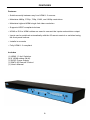
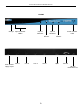
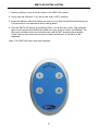
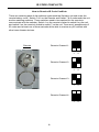
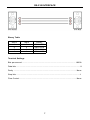
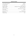
4x1 Switcher For
1.3
EXT-HDMI1.3-441
User Manual
www.gefen.com
f
ASKING FOR ASSISTANCE
Technical Support:
Telephone
(818) 772-9100
(800) 545-6900
Fax
(818) 772-9120
Technical Support Hours:
8:00 AM to 5:00 PM Monday thru Friday.
Write To:
Gefen Inc.
c/o Customer Service
20600 Nordhoff St
Chatsworth, CA 91311
www.gefen.com
[email protected]
Notice
Gefen Inc. reserves the right to make changes in the hardware, packaging and any
accompanying documentation without prior written notice.
HDMI 1.3 4x1 Switcher is a trademark of Gefen Inc.
HDMI is a trademark of HDMI.org
© 2007 Gefen Inc., All Rights Reserved
TABLE OF CONTENTS
1
Introduction
2
Features
3
Panel Descriptions
4
Connecting and Operating the HDMI 1.3 4x1 Switcher / Device Buttons
5
RMT4-IR Installation
6
IR Code Conflicts
7
RS-232 Interface
8
Specifications
9
Warranty
INTRODUCTION
Congratulations on your purchase of the HDMI 1.3 4x1 Switcher. Your complete
satisfaction is very important to us.
The HDMI 1.3 4x1 Switcher allows four HDTV HDMI devices to be switched easily
into one HDTV HDMI compatible monitor or projector. Simply connect your HDTV
display to the Switcher’s display output. The HDMI 1.3 4x1 Switcher can also be
placed at the end of a long HDMI cable to regenerate the HDMI signal.
Our Commitment
Gefen will always offer the finest quality product at the best possible price. Included
in that price is a lifetime support from a team of outstanding engineers.
Gefen’s line of HDTV switches, extenders, and splitters are designed to make your
A/V equipment use more comfortable, more productive and less expensive. Gefen
offers solutions for home theater, A/V installation, data center, information distribution, conference room presentation, school and corporate training environments.
1
FEATURES
Features
• Switches easily between any four HDMI 1.3 sources
• Maintains 480i/p, 576i/p, 720p, 1080i, and 1080p resolutions
• Maintains highest HDMI single link video resolution
• Supports HDCP compliant devices
• HDMI or DVI to HDMI cables are used to connect the inputs and switcher output
• Inputs can be switched automatically with the IR remote control or switched using
the front panel buttons
• Installs in seconds
• Fully HDMI 1.3 compliant
Includes
(1) HDMI 1.3 4x1 Switcher
(4) 6' HDMI cables (M-M)
(1) 5VDC Power Supply
(1) RMT4-IR Remote Control
(1) User's Manual
2
PANEL DESCRIPTIONS
FRONT
IR Eye
Input Indicator
LED’s
Power Indicator
LED
Input 3
Selector
Input 1
Selector
Input 2
Selector
Input 4
Selector
BACK
Input 1
Input 2
Input 3
Input 4
5VDC Power
Supply Input
HDMI
Output
RS-232
Control Port
IR Eye
Extension Port
3
CONNECTING AND OPERATING THE HDMI 1.3 4x1 SWITCHER
How to Connect the HDMI 1.3 4x1 Switcher to your devices
1. Connect the supplied cables from the HDTV HDMI sources into the HDMI 1.3 4x1
Switcher inputs.
2. Connect the cable from your display (monitor or projector) into the HDMI out of the HDMI
1.3 4x1.
3. Plug the 5VDC power supply into the HDMI 1.3 4x1 Switcher.
How to Control the HDMI 1.3 4x1 Switcher
Use the RMT4-IR remote control to toggle between sources or press the input buttons
located on the front of the HDMI 1.3 4x1. You can also control the unit using the integrated
RS-232 serial connection on the rear of the unit. Please see the RS-232 control section for
more details.
4
RMT4-IR INSTALLATION
1. Remove battery cover from the back of the RMT4-IR remote.
2. Verify that dip switches 1 & 2 are in the down (OFF) position.
3. Insert the battery, hold the battery so that you can see the positive side facing up.
The side that is not marked must be facing down.
4. Test the RMT4-IR remote by pressing ONLY one button at a time. The indicator
light on the remote will flash once each time you press a button. WARNING: Do
not press multiple buttons simultaneously and do NOT press buttons rapidly.
These actions will cause the remote to reset and steps 1-4 will have to be
repeated.
Note: The RMT4-IR ships with two batteries.
5
IR CODE CONFLICTS
How to Resolve IR Code Conflicts
There are matching pairs of dip switches underneath the Switcher unit and under the
remote battery cover. Switch 1 & 2 on the Remote and Switch 7 & 8 underneath the unit
are the matching switches. These switches need to be matched for the remote to
communicate with the switcher. Switch 1 on the remote is linked to switch 8 on the unit,
and switch 2 on the remote is linked to switch 7 on the unit. There are 4 possible sets of
IR codes and at least one of these sets should be able to resolve any IR conflicts with
other home theater devices.
Remote
Remote Channel 1:
1
2
1
2
1
2
1
2
Remote Channel 2:
Remote Channel 3:
Remote Channel 4:
6
RS-232 INTERFACE
Binary Table
ASCII
1
2
3
4
Input
1
2
3
4
Binary
0011 0001
0011 0010
0011 0011
0011 0100
Terminal Settings
Bits per second ................................................................................................. 19200
Data bits .................................................................................................................... 8
Parity .................................................................................................................. None
Stop bits .....................................................................................................................1
Flow Control ....................................................................................................... None
7
SPECIFICATIONS
Video Amplifier Bandwidth .............................................................................340 MHz
Input Video Signal ....................................................................................1.2 volts p-p
Input DDC Signal ...............................................................................5 volts p-p (TTL)
Single Link Range .........................................1080p/60 16 bit color depth, 1920x1200
HDMI Connector ..........................................................................type A 19 pin female
Remote Control Port ..........................................................RS232 female, mini-stereo
Power Supply ....................................................................................................5V DC
Power Consumption .............................................................................10 watts (max)
Dimensions .............................................................................13.25”W x 1”H x 2.75”D
Shipping Weight .................................................................................................. 6 lbs
8