1
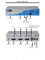
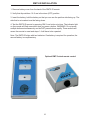
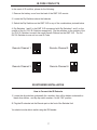
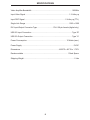
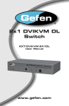
2x1 DVI KVM SL
Switcher
USER
MANUAL
www.gefen.com
ASKING FOR ASSISTANCE
Technical Support:
Telephone
(818) 772-9100
(800) 545-6900
Fax
(818) 772-9120
Technical Support Hours:
8:00 AM to 5:00 PM Monday thru Friday.
Write To:
Gefen Inc.
c/o Customer Service
20600 Nordhoff Street
Chatsworth, CA 91311
www.gefen.com
[email protected]
Notice
Gefen Inc. reserves the right to make changes in the hardware, packaging and any
accompanying documentation without prior written notice.
2x1 DVI SL Switcher is a trademark of Gefen Inc.
© 2007 Gefen Inc., All Rights Reserved
TABLE OF CONTENTS
1
Introduction
2
Features
3
Panel Descriptions
4
Connecting and Operating the SL Switcher
5
Operation Notes
6
RMT2-IR Installation
7
IR Code Conflicts / IR Extender Installation
8
Specifications
9
Warranty
INTRODUCTION
Congratulations on your purchase of the Gefen 2x1 DVI SL Switcher. Your complete
satisfaction is very important to us.
Gefen’s line of KVM (Keyboard Video & Mouse), DVI, USB, switches, extenders, converters and hubs is designed to make computer use more comfortable, more productive
and less expensive. KVM switches allow access to multiple computers from a single
keyboard, while the extenders give the user control over a computer up to 330 feet
away from the work area.
Gefen products offer solutions for noise, space and security concerns, data center control, information distribution, conference room presentation, and school and corporate
training environments.
Our Commitment
Gefen will always offer the finest quality product at the best possible price. Included in
that price is a lifetime of free support from a team of outstanding engineers.
Now you can switch easily and reliably between any combination of two single link DVI
& USB 2.0 equipped computers (PC or Mac) - using only one keyboard, display and
mouse. The SL cross platform switcher saves space - there’s no need to work on a desk
crowded with double displays, keyboards and mouse devices. It saves time - there’s no
need to move from one monitor to another to access different computers. And, it saves
money - there’s no need to purchase additional displays, mouse devices, keyboards etc.
1
FEATURES
Features
• Saves money on hardware costs
• Saves space on your desktop
• Save time and increase your productivity
• Maintains highest 1920 x 1200 x 60Hz resolution video
• No loss of quality
• Use either PC or Mac with USB keyboard/mouse
• Switches easily between any two single link DVI computers
• Switch between two single link DVI, USB 2.0 and Audio Sources
• IR Remote control
Includes:
(1) 2x1 DVI SL Switcher
(1) 5v Power Supply
(1) RMT2-IR Remote Control
(2) 6ft Single Link DVI cables
(2) 6ft USB cables
(2) Audio cables
(1) Users Manual
2
PANEL DESCRIPTIONS
Power Indicator
Infrared
Eye
Selector
Indicates which
input is selected
Audio In 1
5VDC Input
DVI In 1
Contact Closure Interface
- Connects to optional wired
Audio Out RMT-2 remote control
Audio In 2
DVI Out
DVI In 2
USB In 1
USB
Output
3
USB In 2
CONNECTING AND OPERATING THE 2x1 DVI SL SWITCHER
How to Connect the SL Switcher to your devices
1- Connect the supplied cables from your first computer into the DVI In 1, USB In 1,
and Audio In 1 connection in the back of the DVI Switcher.
2- Connect the supplied cables from your second computer into the DVI In 2, USB In 2,
and Audio In 2 connection in the back of the DVI Switcher.
3- Connect the monitor to the DVI Out connection.
4- Connect your USB devices (e.g. keyboard, mouse) into the USB Out.
5- Connect your speakers to the Audio Out.
6- Plug the 5VDC power supply into the SL Switcher.
How to Operate the SL Switcher
1- Use the front panel push button to switch between sources.
2- Use the RMT2-IR remote control port to remotely toggle between sources.
3- Use the optional RMT-2 wired remote control to remotely toggle between sources.
4
2x1 DVI SL OPERATION NOTES
Operation Notes
When turning on or rebooting your computers, the DVI SL Switcher must be selected to
the computer that is booting until the computer completes the boot cycle. This step can
be eliminated using the Gefen DVI Detective, which stores the displays EDID.
If you loose your picture when switch from source 1 to source 2 or vice-versa you will
need a DVI Detective.
If you are experiencing USB dropouts try using the switcher just as a USB hub by only
connecting the USB cables from your computers to the switcher. Connect your devices
to the USB out portion of the switcher and connect your display to your computer
directly. Start your computer up and try switching. If your USB devices do come
up normally then you will need a DVI Detective to negotiate the video/USB signals
for faster switching. If they do not come up normally, then you will need to call tech
support.
5
RMT2-IR INSTALLATION
1. Remove battery cover from the back of the RMT2-IR remote.
2. Verify that dip switches 1 & 2 are in the down (OFF) position.
3. Insert the battery, hold the battery so that you can see the positive side facing up. The
side that is not marked must be facing down.
4. Test the RMT2-IR remote by pressing ONLY one button at a time. The indicator light
on the remote will flash once each time you press a button. WARNING: Do not press
multiple buttons simultaneously and do NOT press buttons rapidly. These actions will
cause the remote to reset and steps 1-4 will have to be repeated.
Note: The RMT2-IR ships with two batteries. One battery is required for operation, the
second battery is complimentary.
Optional RMT-2 wired remote control
6
IR CODE CONFLICTS
In the event of IR conflicts, please do the following:
1. Remove the battery cover from the back of the RMT 2-IR remote.
2. Locate the Dip Switches above the batteries
3. Switch the Dip Switches on the RMT 2-IR to any of the combinations pictured below.
4. Dip Switches 1 and 2 in the RMT 2-IR correspond with Dip Switches 1 and 2 on the
outside of the 2x1 DVI SL Switcher respectively. Flip the switches on the outside of the
2x1 DVI SL Switcher to match the same Remote Channel as the RMT 2-IR. The 2x1
DVI SL Switcher is now set to a new IR Code.
Remote Channel 2:
Remote Channel 1:
1
2
1
2
1
2
Remote Channel 4:
Remote Channel 3:
1
2
IR EXTENDER INSTALLATION
How to Connect the IR Extender
1 Locate the dip switches underneath the switcher, they will be hidden underneath a
blank silver sticker, and flip dip switch number 4 to the "ON" position.
2 Plug the IR extender into the Remote port on the front of the Switcher Unit
You should now be able to switch using the IR Extender.
7
SPECIFICATIONS
Video Amplifier Bandwidth ................................................................................. 165 MHz
Input Video Signal ........................................................................................ 1.2 Volts p-p
Input DDC Signal .................................................................................. 5 Volts p-p (TTL)
Single Link Range ........................................................................................ 1920 x 1200
DVI Input/Output Connector Type ................................ DVI-I 29 pin female (digital only)
USB 2.0 Input Connection .................................................................................. Type “B”
USB 2.0 Output Connection ............................................................................... Type “A”
Power Consumption ............................................................................... 15 Watts (max.)
Power Supply ........................................................................................................ 5V DC
Dimensions ............................................................................. 4.625”D x 8.5”W x 1.75”H
Rackmountable ......................................................................................... 1 Rack Space
Shipping Weight ...................................................................................................... 5 Lbs
8