1
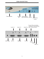
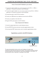
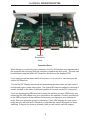
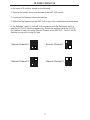
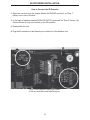
2x1 DVI DL
Switcher
USER
MANUAL
www.gefen.com
ASKING FOR ASSISTANCE
Technical Support:
Telephone
(818) 772-9100
(800) 545-6900
Fax
(818) 772-9120
Technical Support Hours:
8:00 AM to 5:00 PM Monday thru Friday.
Write To:
Gefen Inc.
c/o Customer Service
20600 Nordhoff Street
Chatsworth, CA 91311
www.gefen.com
[email protected]
Notice
Gefen Inc. reserves the right to make changes in the hardware, packaging and any
accompanying documentation without prior written notice.
2x1 DVI DL Switcher is a trademark of Gefen Inc.
© 2007 Gefen Inc., All Rights Reserved
TABLE OF CONTENTS
1
Introduction
2
Features
3
Panel Descriptions
4
Connecting and Operating the DL Switcher
5
Operation Notes
6
RMT2-IR Installation
7
IR Code Conflicts
8
IR Extender Installation
9
Specifications
10
Warranty
INTRODUCTION
Congratulations on your purchase of the Gefen 2x1 DVI DL Switcher. Your complete
satisfaction is very important to us.
Gefen’s line of KVM (Keyboard Video & Mouse), DVI, ADC, USB, switches, extenders,
converters and hubs is designed to make computer use more comfortable, more productive and less expensive. KVM switches allow access to multiple computers from a
single keyboard, while the extenders give the user control over a computer up to 330
feet away from the work area.
Gefen products offer solutions for noise, space and security concerns, data center control, information distribution, conference room presentation, and school and corporate
training environments.
Our Commitment
Gefen will always offer the finest quality product at the best possible price. Included in
that price is a lifetime of free support from a team of outstanding engineers.
Now you can switch easily and reliably between any combination of two dual link DVI
& USB 2.0 equipped computers (PC or Mac) - using only one keyboard, display and
mouse. The DL cross platform switcher saves space - there’s no need to work on a desk
crowded with double displays, keyboards and mouse devices. It saves time - there’s no
need to move from one monitor to another to access different computers. And, it saves
money - there’s no need to purchase additional displays, mouse devices, keyboards etc.
1
FEATURES
Features
• Saves money on hardware costs
• Saves space on your desktop
• Save time and increase your productivity
• Maintains highest 3840 x 2400 x 60Hz resolution video
• No loss of quality
• Use either PC or Mac with USB keyboard/mouse
• Switches easily between any two dual link DVI computers
• Switch between two dual link DVI, USB 2.0 and Audio Sources
• IR Remote control
• Rackmountable
Includes:
(1) 2x1 DVI DL Switcher
(1) 5v Power Supply
(1) RMT2-IR Remote Control
(2) 6ft Dual Link DVI cables
(2) 6ft USB cables
(2) Audio cables
2
PANEL DESCRIPTIONS
Power Indicator
5VDC Input
Infrared
Eye
Audio In 1
Audio In 2
DVI In 1
DVI Out
Indicates which
Input
input is selected Selector
Equalization
Knobs
Contact Closure Interface
- Connects to optional wired
Audio Out RMT-2 remote control
DVI In 2
3
USB
Output
USB In 1
USB In 2
CONNECTING AND OPERATING THE 2x1 DVI DL SWITCHER
How to Connect the DL Switcher to your devices
1- Connect the supplied cables from your first computer into the DVI In 1, USB In 1,
and Audio In 1 connection in the back of the DVI Switcher.
2- Connect the supplied cables from your second computer into the DVI In 2, USB In 2,
and Audio In 2 connection in the back of the DVI Switcher.
3- Connect the monitor to the DVI Out connection.
4- Connect your USB devices (e.g. keyboard, mouse) into the USB Out.
5- Connect your speakers to the Audio Out.
6- Plug the 5VDC power supply into the DL Switcher.
How to Operate the DL Switcher
1- Use the front panel push button to switch between sources.
2- Use the RMT2-IR remote control port to remotely toggle between sources.
3- Use the optional RMT-2 wired remote control to remotely toggle between sources.
Equalization control for the DVI DL Switcher
Equalization Knobs
The external equalization knobs can be used to balance out signal noise
resulting from long cables for better picture quality. By turning the equalization knobs
counter-clockwise you will eliminate any noise and/or degradation in the signal. You
should be able to find a "sweet spot" somewhere in the middle.
4
2x1 DVI DL OPERATION NOTES
Internal
Equalization
Knob
Operation Notes
When turning on or rebooting your computers, the DVI DL Switcher must be selected to
the computer that is booting until the computer completes the boot cycle. This step can
be eliminated using the Gefen DVI Detective, which stores the displays EDID.
If you loose your picture when switch from source 1 to source 2 or vice-versa you will
need a DVI Detective.
*For the Dell 30" Display the internal and external equalization knobs will both need to
be adjusted to get a clean video signal. The internal EQ can be reached by removing 9
screws situated on the sides of the casing and the 6 hex nuts on the DVI connectors.
If you are experiencing USB dropouts try using the switcher just as a USB hub by only
connecting the USB cables from your computers to the switcher. Connect your devices
to the USB out portion of the switcher and connect your display to your computer directly. Start your computer up and try switching. If your USB devices do come up normally then you will need a DVI Detective to negotiate the video/USB signals for faster
switching. If they do not come up normally, then you will need to call tech support.
5
RMT2-IR INSTALLATION
1. Remove battery cover from the back of the RMT2-IR remote.
2. Verify that dip switches 1 & 2 are in the down (OFF) position.
3. Insert the battery, hold the battery so that you can see the positive side facing up. The
side that is not marked must be facing down.
4. Test the RMT2-IR remote by pressing ONLY one button at a time. The indicator light
on the remote will flash once each time you press a button. WARNING: Do not press
multiple buttons simultaneously and do NOT press buttons rapidly. These actions will
cause the remote to reset and steps 1-4 will have to be repeated.
Note: The RMT2-IR ships with two batteries. One battery is required for operation, the
second battery is complimentary.
Optional RMT-2 wired remote control
6
IR CODE CONFLICTS
In the event of IR conflicts, please do the following:
1. Remove the battery cover from the back of the RMT 2-IR remote.
2. Locate the Dip Switches above the batteries
3. Switch the Dip Switches on the RMT 2-IR to any of the combinations pictured below.
4. Dip Switches 1 and 2 in the RMT 2-IR correspond with Dip Switches 2 and 3 inside the 2X1 DVI DL Switcher respectively. Switch the switches inside the 2x1 DVI
DL Switcher to match the same Remote Channel as the RMT 2-IR. The 2x1 DVI DL
Switcher is now set to a new IR Code.
Remote Channel 1:
Remote Channel 0:
1
2
1
2
1
2
Remote Channel 3:
Remote Channel 2:
1
2
7
IR EXTENDER INSTALLATION
How to Connect the IR Extender
1 Open the unit and move the jumper labeled INFRARED (pictured* as "Step 1"
below) from Local to Remote
2 In the bank of switches labeled SERVICE SWITCH (pictured* as "Step 2" below), flip
Service Switch #1 (top most switch) to the ON position
3 Reassemble the unit.
4 Plug the IR extender into the Remote port on the front of the Switcher Unit
*Note: Picture depicts upper right corner
of the unit with the power light facing up.
8
SPECIFICATIONS
Video Amplifier Bandwidth .......................................................................... 2x 1.65 Gbps
Input Video Signal ........................................................................................ 1.2 volts p-p
Input DDC Signal .................................................................................. 5 volts p-p (TTL)
Single Link Range ........................................................................................ 3840 x 2400
DVI Input/Output Connector Type ................................ DVI-I 29 pin female (digital only)
USB 2.0 Input Connection .................................................................................. Type “B”
USB 2.0 Output Connection ............................................................................... Type “A”
Power Consumption ............................................................................... 15 Watts (max.)
Power Supply ......................................................................................................... 5VDC
Dimensions ............................................................................. 4.625”D x 8.5”W x 1.75”H
Rackmountable ......................................................................................... 1 Rack Space
Shipping Weight ...................................................................................................... 5 Lbs
9
WARRANTY
Gefen Inc. warrants the equipment it manufactures to be free from defects in material
and workmanship.
If equipment fails because of such defects and Gefen Inc. is notified within two
(2) years from the date of shipment, Gefen Inc. will, at its option, repair or replace
the equipment, provided that the equipment has not been subjected to mechanical,
electrical, or other abuse or modifications.
Equipment that fails under conditions other than those covered will be repaired at the
current price of parts and labor in effect at the time of repair. Such repairs are warranted
for ninety (90) days from the day of reshipment to the Buyer.
This warranty is in lieu of all other warranties expressed or implied, including without
limitation, any implied warranty or merchantability or fitness for any particular purpose,
all of which are expressly disclaimed.
1. Proof of sale may be required in order to claim warranty.
2. Customers outside the US are responsible for shipping charges to and from Gefen.
3. Copper cables are limited to a 30 day warranty and cable must be free from any
scratches, markings, and neatly coiled.
The information in this manual has been carefully checked and is believed to be
accurate. However, Gefen Inc. assumes no responsibility for any inaccuracies that may
be contained in this manual. In no event will Gefen Inc., be liable for direct, indirect,
special, incidental, or consequential damages resulting from any defect or omission
in this manual, even if advised of the possibility of such damages. The technical
information contained herein regarding DL Switcher features and specifications is
subject to change without notice.
10