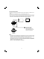
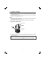
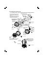
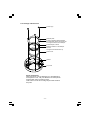
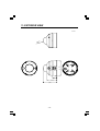
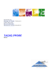
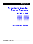
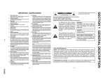
1
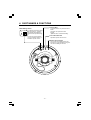
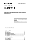
INSTRUCTION MANUAL
CCD COLOR CAMERA
IK-VR01A
Please read this manual thoroughly before use, and keep it handy
for future reference.
Record in space provided below the Model No. and
the Serial No. as found on the label on the bottom
of this unit.
Model. No. IK-VR01A Serial No.
Retain this information for future reference.
TABLE OF CONTENTS
Important safeguards
1. Features & Description .................................................
2. Cautions ........................................................................
3. Components .................................................................
4. Part Names & Functions ...............................................
5. Connections and Operations ........................................
6. Installations ...................................................................
7. Line Lock Phase ...........................................................
8. Note on use and Installation .........................................
9. In Case of Problems .....................................................
10. Specifications ................................................................
11. Exterior View .................................................................
3
3
3
4
5
7
12
12
13
14
15
IMPORTANT SAFEGUARDS
1. Read Instructions
All the safety and operating instructions should
be read before the product is operated.
2. Retain Instructions
The safety instructions and instruction manual
should be retained for future reference.
3. Heed Warnings
All warnings on the product and in the instruction
manual should be adhered to.
4. Follow Instructions
All operating and use instructions should be
followed.
5. Cleaning
Disconnect this video product from the power
supply before cleaning.
6. Attachments
Do not use attachments not recommended by the
video product manufacturer as they may cause
hazards.
7. Water and Moisture
Do not use this video product near water-for
example, near a bath tub, wash bowl, kitchen sink,
or laundry tub, in a wet basement, or near a
swimming pool and the like.
8. Accessories
Do not place this video product on an unstable
cart, stand, tripod, bracket or table. The video
product may fall, causing serious injury to a child
or adult, and serious damage to the product. Use
only with stand, tripod, bracket, or table
recommended by the manufacturer, or sold with
the video product. Any mounting of the product
should follow the manufacturer’s instructions, and
should use a mounting accessory recommended
by the manufacturer.
9. Ventilation
This video product should never be placed near
or over a radiator or heat register. This video
product should not be placed in a built-in
installation such as a bookcase or rack unless
proper ventilation is provided or the manufacturer’s
instructions have been adhered to.
10.Power Sources
This video product should be operated only from
the type of power source indicated on the marking
label. If you are not sure of the type of power
supply to your location, consult your product
dealer.
11.Power-Cord Protection
Power-Supply cords should be routed so that they
are not likely to be walked on or pinched by items
placed upon or against them, paying particular
attention to cords at plugs, screws and the point
where they exit from the product.
12.Installation
This video product should be installed on a firm
and solid part of the ceiling or wall. If installed on
a soft and weak place, the camera unit may fall.
A person under it may be injured and things under
it may be damaged.
13.Lightning
For added protection for this video product during
a lightning storm, or when it is left unattended and
unused for long periods of time, unplug it from
the wall outlet and disconnect the power supply
and cable system. This will prevent damage to
the video product due to lightning and power-line
surges. However, if there is thunder or lightning
now, do not touch the unit and any connected
cable. This will for you not to receive the electric
shock by the serge of thunder.
14.Overloading
Do not overload power supply and extension cords
as this can result in a risk of fire or electric shock.
15.Object and Liquid Entry
Never push objects of any kind into this video
product through openings as they may touch
dangerous voltage points or short-out parts that
could result in a fire or electrical shock. Never spill
liquid of kind on the video product.
16.Servicing
Do not attempt to service this video product
yourself as opening or removing covers may
expose you to dangerous voltage or other hazards.
Refer all servicing to qualified service personnel.
17.Damage Requiring service
Disconnect this video product from the power
supply and refer servicing to qualified service
personnel under the following conditions.
a. When the power-supply cord or plug is
damaged.
b. If liquid has been spilled, or objects have fallen
into the video product.
c. If the video product has been exposed to rain
or water.
d. If the video product does not operate normally
by following the operating instructions in the
instruction manual. Adjust only those controls that
are covered by the instruction manual as an
improper adjustment of other controls may result
in damage and will often require extensive work
by a qualified technician to restore the video
product to its normal operation.
e. If the video product has been dropped or the
cabinet has been damaged.
f. When the video product exhibits a distinct
change in performance-this indicates a need for
service.
18.Replacement Parts
When replacement parts are required, be sure
the service technician has used replacement parts
specified by the manufacturer with the same
characteristics as the original part. Unauthorized
substitutions may result in fire, electric shock or
other hazards.
19.Safety Check
Upon completion of any service or repairs to this
video product, ask the service technician to
perform safety checks to determine that the video
product is in proper operating condition.
-1-
• The CAUTION label, shown on the left,
is attached on the camera.
CAUTION TO REDUCE THE RISK OF ELECTRIC SHOCK.
DO NOT REMOVE COVER (OR BACK).
NO USER SERVICEABLE PARTS INSIDE.
REFER SERVICING TO QUALIFIED SERVICE PERSONNEL.
The lightening flash with arrowhead
symbol, within an equilateral triangle,
is intended to alert the user to the
presence of uninsulated “dangerous
voltage” within the product’s enclosure
that may be of sufficient magnitude to
constitute a risk of electric shock to
persons.
The exclamation point within an
equilateral triangle is intended to alert
the user to the presence of important
operating and maintenance (servicing)
instructions in the literature
accompanying the appliance.
WARNING :
TO REDUCE THE RISK OF FIRE OR
ELECTRIC SHOCK, DO NOT EXPOSE
THIS APPLIANCE TO RAIN OR
MOISTURE.
CAUTION :
CONNECT 24V AC UL LISTED CLASS 2
POWER SUPPLY.
FIELD INSTALLATION :
WORDED : “THIS INSTALLATION SHOULD
BE MADE BY A QUALIFIED SERVICE
PERSON AND SHOULD CONFORM TO
ALL LOCAL CODES.”
FCC NOTICE
This equipment has been tested and found to comply with the limits for a Class A digital device,
pursuant to Part 15 of the FCC Rules. These limits are designed to provide reasonable protection
against harmful interference when the equipment is operated in a commercial environment.
This equipment generates, uses, and can radiate radio frequency energy and, if not installed
and used in accordance with the instruction manual, may cause harmful interference to radio
communications. Operation of this equipment in a residential area is likely to cause harmful
interference in which case the user will be required to correct the interference at his own expense.
USER-INSTALLER CAUTION : Your authority to operate this FCC verified equipment could be
voided if you make changes or modifications not expressly approved by the party.
Serial No Label
The serial No. label is located here.
-2-
1. FEATURES & DESCRIPTION
IK-VR01A has the following features:
(1) Flush/Surface mount.
(2) IP66 Standard for dust and water resistance.
(3) Built in vari-focal lens with auto-iris
Focal length 3.0~8.0mm.
(4) Incorporated 1/3" type CCD image sensor gives high resolution and excellent
sensitivity
480 lines horizontal resolution
0.4 lx minimum illumination with tint dome cover
(5) 50dB Signal-To Noise Ratio
(6) Power supply- AC24V or DC12V - This camera automatically detects the power.
(7) BLC, AGC, and Line-Lock (AC24V)
2. CAUTIONS
(1) Avoid touching the lens glass with your fingers. If necessary, use a soft cloth
moistened with alcohol to wipe off any dust.
(2) Avoid aiming the camera at the sun.
(3) Avoid shooting the camera at intense light. Intense light such as a spotlight may
cause a bloom or smear. A vertical stripe may appear on the screen.
However, this is not a malfunction.
(4) Install the camera away from video noise. If cables are wired near electric lighting
wires or a TV set, noise may appear in images. In this event, relocate cables or
reinstall equipment.
3. COMPONENTS
(1) Camera (with Tint Dome Cover installed)
(2) Accessories
(a) Mounting Base
(b) Bracket
(c) Screw A
(d) Screw B
(e) Clear Dome Cover
(f) Special Hexangular Wrench
(g) Monitor Out Harness Wire
(h) Power Connector
(i) Instruction Manual
-3-
1 pc.
1 pc.
1 pc.
3 pcs.
3 pcs.
1 pc.
1 pc.
1 pc.
1 pc.
1 pc.
4. PART NAMES & FUNCTIONS
Lens Iris ADJ
Mode Setting Switch
LL BLC
ON
OFF
Counterclockwise: The picture becomes
darker.
Clockwise: The picture becomes
brighter.
"Optimum Value" is at default setting.
BLC (Backlight Compensation Switch)
With the switch on, it adjusts
the backlight automatically to
obtain the best possible image.
LL
Sets camera synchronization
to line lock with the switch on.
Available only with AC24V.
Line Lock Phase ADJ
Adjusts the phase of the line lock.
Monitor Out Connector
Connect with the supplied monitor out
harness wire. Used to adjust the angle of
view when installing the camera.
-4-
5. CONNECTIONS AND OPERATIONS
Notes on connecting
• Power plugs to connected equipment must be disconnected before installation.
• A 75-ohm coaxial cable (3C-2V or 5C-2V) is required for standard connection.
• For details of wiring and operation of equipment to be connected, refer to their
operation manuals.
• Coaxial cables for video signals and the power cord are not supplied with the
camera.
Refer to the operations manuals of connected equipment for detailed wiring and
overall operation instructions.
5-1 Basic connection single system configuration
Video Monitor
BNC Connector
Supplied Power Connector
( ) POWER CORD (twisted pair line)
minimum wire size of 18 AWG is recommended.
12V DC
AC 120V
24V AC UL Listed Class 2 power supply / 12V DC power supply
CAUTION : Never input 24V AC and 12V DC at the same time.
In case of DC12V, connect “+12” to red cable and “GND” to black cable.
Do not overload power supply
Since this camera uses 24V AC UL Listed Class 2 power supply or 12V DC power
supply, it should be connected to a power supply that allows for at least 5w
consumption. Because the IK-VR01A uses a mechanism, a sufficient power supply
with adequate current specifications is required.
-5-
5-2 Line-Lock Control
• Matching the vertical synchronization with the power frequency is called the LineLock.
• This function is activated when the LL of Mode Setting Switch is on.
• When two or more cameras are switched by the video switcher for viewing by a monitor
TV, the vertical sync. phase can be locked with the power frequency, and a stable
vertical sync. is obtained without being disturbed at the time of switching.
Video Monitor
VIDEO SWITCHER
CAMERA1
TO AC 24V UL Listed
class 2 power supply
• When connecting to DC
power supply, the Line-Lock
function is not activated.
CAMERA2
Note :
• The camera is synchronized to the power frequency of 60±1Hz covering a normal
fluctuation of the power frequency. However, the camera may not cover a large
fluctuation caused from the power generated by an engine generator, etc.
• It takes about 10 seconds or more until a stable synchronization is obtained after
the power is turned on. This is normal, because several seconds are required to
stabilize the camera against power noise.
• Refer to “7. LINE-LOCK PHASE” for adjustment.
-6-
6. INSTALLATIONS
• Connect the cable of the camera and the cable from the designated power supply
with respective connectors.
• Screws for fixing the camera and mounting base to the ceiling or wall are not supplied
with the unit. Use appropriate screws.
Note :
• The weight (camera body only) is about 1.3kg. The camera unit including the mounting
base and the bracket weighs 2.1kg.
• When installing to surfaces of other materials, use the screws to fix it firmly.
6-1 Adjust the Angle of View
Security screws
Top Cover
a
Camera Base
(1) Loosen the three security screws by the supplied special hexangular wrench and
remove the top cover.
Important Notice :
Be sure to remove three silver screws a immediately after removing the top
cover. The screws are used to temporarily fix the top cover for transportation.
-7-
Tilt rotation
Horizontal
rotation
a
2
Tilt Lock
a
FAR
∞
1 Pan Lock
a
Pan
4 Focus
lock lever NEAR
Remove three silver
screws transport protection.
WIDE
TELE
3 Zoom
lock lever
a Transport Protection Screws (silver)
(2) The lens direction in pan direction can be adjusted by turning pan lock 1
counterclockwise to unfasten it without moving the lens. After adjustment, turn pan
lock 1 clockwise to fasten it.
Note :
• Do not turn the lens over 360°. Otherwise the inner connector may be broken and
the image may not appear.
(3) The lens tilt angle can be adjusted by loosening the tilt lock 2. After adjusting,
tighten the tilt lock 2.
(4) Adjust the zoom position by loosening the zoom lock lever 3. After adjusting,
tighten the zoom lock lever 3.
(5) Adjust the focus by loosening the focus lock lever 4. After adjusting, tighten the
focus lock lever 4.
(6) Repeat the adjustments from step (1) to step (5) till the optimum image appears.
-8-
6-2 Installing the Camera Unit
6-2-1 Installation to Wall or Ceiling with Mounting Base (Surface Mount Installation)
A
Cable access hole ø27 mm
B
46 mm
C
Mounting Base center
46 mm
7
• When installing the camera unit on the
wall, mount it with the drain groove on
the downside. Do not block the drain
groove.
• When installing the camera unit outdoor,
make waterproof for the cables. The
camera body is water-resistant but the
brackets are not water-resistant.
83.5 m
m
85 mm
Mounting Base center
55 mm
83.5 m
m
Mounting Base
Drain groove
7
A , C Wall or Ceiling
85 mm
B , D Junction Box
55 mm
Cable access hole
ø27 mm
With female screw for piping
Cable exit
(sideway)
Rear cable hole
Screws (not supplied)
x4
Fix firmly.
Drain groove
D
In case of using the
variable mounting
holes
Align to this mark.
Screws
x3
Mount the top cover (the
assembly of the dome
cover) and secure it firmly
with three security screws
by the supplied special
hexangular wrench.
Mount camera base with three supplied
screws A. (Longer screw(M4x16))
Tighten and lock the screws firmly.
Top Cover
Camera Base
Align to this mark.
-9-
6-2-2 Installation to Junction Box with Bracket (Flush Mount Installation)
46 mm
Junction Box
83.5 mm
Bracket
Screws (not supplied)
x4
Note the direction of
the bracket, which has
two sides.
Align the marks.
Screws
x3
Mount camera base with three supplied
screws B. (Shorter screw(M4x10))
Tighten and lock the screws firmly.
Mount the top cover (the assembly
of the top dome cover) and secure
it firmly with three security screws
by the supplied special hexangular
wrench.
Align to this mark.
- 10 -
6-2-3 Change of Dome Cover
Screws (x3)
Retainer plate
Put the protruding side downward.
The protruding portion should be set
in the groove of the shock damper.
Shock damper cushion
Note the direction of the damper
cushion.
The groove should be face up.
Dome cover
Gasket
Top cover
Dome replacement
When the dome cover is damaged or to be replaced by
a transparent cover, call your distributor or sales person.
Firmly tighten three mounting screws.
Take care not to let dirt or foreign object enter between
the parts.
- 11 -
7. LINE LOCK PHASE
When a video switcher switches two or more cameras, the picture may fluctuate on the
video monitor due to the different AC line phase of each camera. In this case, adjust the
V PHASE controller to get a stable image.
Line Lock V PHASE CONTROL
8. NOTE ON USE AND INSTALLATION
• Do not aim the camera at the sun
Do not aim the camera at the sun or point it at sun even if you are not shooting.
• Do not shoot intense light
Intense light such as a spotlight may cause a bloom or smear. A vertical stripe may
appear on the screen. However, this is not a malfunction.
• Treat the camera with care
Do not drop the camera or subject it to strong shock of vibration. Otherwise, the camera
may malfunction.
• Never touch internal parts
Do not touch the internal parts of the camera other than the parts specified. Otherwise,
the camera may malfunction.
• Do not splash water on the camera
Install the camera where the camera can be kept dry. If the camera gets wet, turn off
the power and contact your dealer.
• Check the ambient temperature and humidity
Avoid using the camera where the temperature is hotter or colder than specified.
Otherwise, the quality of images may deteriorate or internal parts may be affected.
Special care is required to use the camera at high temperature and humidity.
• Should you notice any trouble
If any trouble occurs while you are using the camera, turn off the power and contact
your dealer. If you continue to use the camera when there is something wrong with it,
the trouble may much worse and an unpredictable accident may occur.
- 12 -
9. IN CASE OF PROBLEMS
Condition
No image
Check Points
• Are the camera and connected equipment turned on?
• Are cables connected correctly?
• Is the monitor TV adjusted correctly?
Unnatural color
• Is the lighting too weak?
The image is out of • Is the lens focus adjusted?
• Is the lens or cover dirty?
focus.
The image is dark. • Are there any large barrier or bright illumination near the
camera?
• Is the lens iris adjustment volume correctly set?
- 13 -
10. SPECIFICATIONS
1. Image System
Image Device
Pixel Elements
2. Electrical
TV System
1/3” IT CCD
771 (H) x 492 (V)
2:1 Interlace, 15.734KHz Horizontal, 59.94Hz
Vertical
Horizontal Resolution
480 TV lines
S/N Ratio
50dB (TYP. White 100%, Weight On, SC TRAP ON)
0.2 lux (More than 10% of image output, Clear dome cover)
Minimum Illumination
0.4 lux (More than 10% of image output, Tint dome cover)
Auto Gain Control (AGC)
Average AGC (24dB)
Iris Control Mode
Auto Iris Lens
White Balance
Auto
White Balance Range
2500°K ~ 10000°K
Line lock Vertical phase adjustment Provided (VR : range 300deg)
Gamma compensation
0.45
Backlight Compensation (BLC) On / Off (DIP-SW)
Video Output Signal
VBS (1.0Vp-p, 75ohm unbalance, BNC)
Synchronization System
Internal for DC or Linelock for AC
3. Mechanical
Weight
Camera : 1.3kg, Mounting Base : 0.6kg,
Bracket : 0.2kg
Camera : 170mm (D) x 150mm (H)
Dimension
with Mounting Base : 175mm (D) x 155mm (H)
4. Optical
Built-in Lens
Vari-focus Lens
f=3.0 ~ 8.0mm, F1.0 (Wide) /F1.45 (Tele) : Auto Iris
Wide : 117.3° (D), 90.8° (H), 66.6° (V)
View Angle
Tele : 45.2° (D), 36.2° (H), 27.0° (V)
Focus Length
0.2m ~ ∞
5. Power
Input Voltage
DC12V or AC24V
Power Consumption
3.0W
6. Environmental
Operating Temperature
-10°C~50°C 90%RH max
Storage Temperature
-20°C~60°C 70%RH max
Water proof:IP66
7. Regulation
Safety
UL2044
Dust and Water Resistance IP66
Emission
FCC Class A / DOC ClassA
Design and specifications are subject to change without notice.
- 14 -
11. EXTERIOR VIEW
unit : mm
)
( φ 175 )
5.5
( SR 4
( 48.5 )
( 110 )
( 155 )
- 15 -
unit : mm
( SR
45.5
)
( φ 170 )
( 150 )
( 61.5 )
( 147.5 )
- 16 -
( 41 )
■
Bracket
unit : mm
120
46
110
120
83.5
60
4-M4
4- φ 4.5
4- φ 6.5
■
Mounting Base
85
46
4.4
20
6- φ 5.5
82
4-M6 Depth=10
114
40
85
83.5
15
4- φ 6.5
15
7
5
φ 27
15
40
15
55
- 17 -
- 18 -